Rupnow i.c. Engine with governor

Home Model Engine Machinist Forum

Help Support Home Model Engine Machinist Forum:

This site may earn a commission from merchant affiliate links, including eBay, Amazon, and others.
Brian,
Before pointing out a mistake I meant to first thank you for another great design and build. It is also very kind of you to try to include other people into your build process. Thank you very much for all of the hard work.

Pat W
 
Brian,
Before pointing out a mistake I meant to first thank you for another great design and build. It is also very kind of you to try to include other people into your build process. Thank you very much for all of the hard work.

Pat W

different person different point of view.:hDe:

I notice that also, but it did look as a counter sunk of .125 in a 1.125 diameter:fan:
those numbers sometime
 
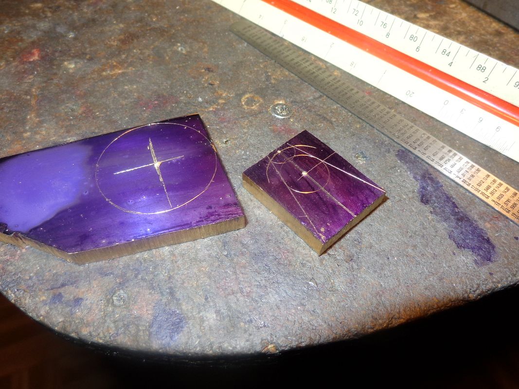
The cam gear---Ah, yes. That could end up being a pig of a different color!! I have all these scraps of 1/4" brass plate laying around, and I try and utilize them whenever/however I can. Now you didn't hear it from me, but---the overall cam profile on these small single cylinder engines is not nearly as critical as some people would have you believe. Oh yes, it has to have the correct general profile, and the sides must be smooth and cut at 90 degrees to the face. You can spend a lot of time with fancy set-ups in rotary tables and on your lathe machining the profiles. --And that's not wrong.--However----There is ANOTHER way. If this starts to sound like blasphemy, cover your ears---You can lay the profile out with your old drafting compass and a steel scale, scribe out the tangent lines, and cut it out with a bandsaw, then file and beltsand "to the line". Does it work?--Darn right it does. I have used that method on my last two engines, and they run fine. Now the gear itself is a different story. It has to be "dead nuts" as per the gear tables. The hardest part of what I am about to do is to get the reamed hole thru the 1/4" plate which will become a 1/4" wide gear and not have any run-out. If you get it all machined and then find that you have any "run-out" (axis of hole not perfectly square to face of plate in two 90 degree planes)--Then you either have to A--Live with a wobbly gear, or B--Machine both sides until the gear no longer appears to wobble---But then it is less than 1/4" thick. In situations like this, I don't really trust the vice. I clamp the pieces of plate to my mill table with a sacrificial plate underneath it and then drill and ream the center hole. With two 1/4" plates soldered together, the problem only gets worse. However, I've just spent enough time explaining what I am going to do to have actually done the job!!! Onward and upward-----
 
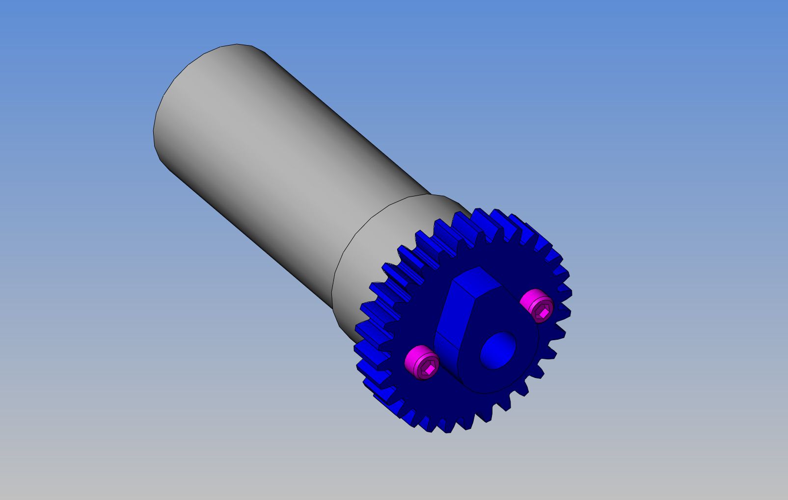
I've been thinkin', Lincoln---Sooner or later I'm going to have to hold that cam gear on a stub arbor to cut the teeth. I have lots of cold rolled "shorts" in my shop. If I drilled and tapped the end of a chunk of 1" cold rolled and "faced" the end of it---Then I could solder the profiled cam to the gear plate, bolt the gear plate to the end of the stub arbor, hold the stub arbor in my lathe to drill and ream the center hole and turn the o.d. of the gear plate to what it should be, then hold the stub arbor in my rotary table chuck to cut the gear teeth. Probably drill and ream undersized holes in both pieces of brass first for an alignment dowel to line the cam up concentric with what will become the center of the gear plate before soldering them together----
 
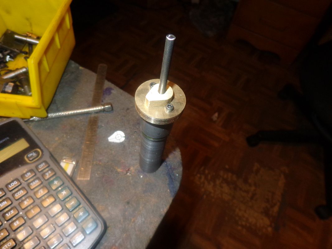
Don't follow me---I'm lost!! Well, not really. Everything is working out as planned----so far. I'm almost ready to cut the gear, but first I have to determine how to solder that cam to the side of the gear without soldering the 3/16" guide shaft into place. I may just solder the guide in place then cut it off, put the stub arbor back in the lathe and drill it out, then drill and ream to 1/4" finished size. I'm making it up as I go along---
 
Brian, use a 3/16th piece of aluminum for the stub arbor. Solder won't stick to it.

By the way great job as always.


Ron
 
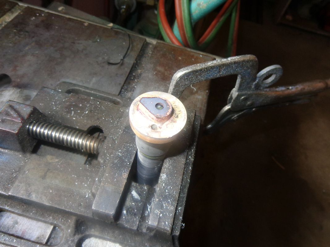
I put flux in the appropriate areas, cut 4 very small pieces of silver solder to set underneath the cam, and removed the socket head capscrews so as not to solder them in place. I cut the 3/16" central locating shaft of flush with the outside of the cam. There is a drilled and reamed 3/16" hole in the center of my stub arbor, and that bit of 3/16" shaft passes thru the cam, the gear blank, and into the hole in the stub arbor to keep everything concentric. I heated the gear blank and the cam with my oxy acetylene torch until I seen liquid solder begin to run out around the edges of the cam. I used a big old screwdriver in my other hand to put some "down force" on the cam to make certain it seated against the face of the gear blank. Its setting out in the garage now cooling off.
 
Brian, use a 3/16th piece of aluminum for the stub arbor. Solder won't stick to it.

By the way great job as always.


Ron
Too late Ozzie--and I have tried that, and solder DID stick to it.--Not a good bond, but enough to screw up what I was doing.
 
I must have had a brain freeze or something.:wall::wall: I was thinking soft solder not silver solder.

I thought aluminum melted before silver solder did. Oh well live and learn.

Ron
 
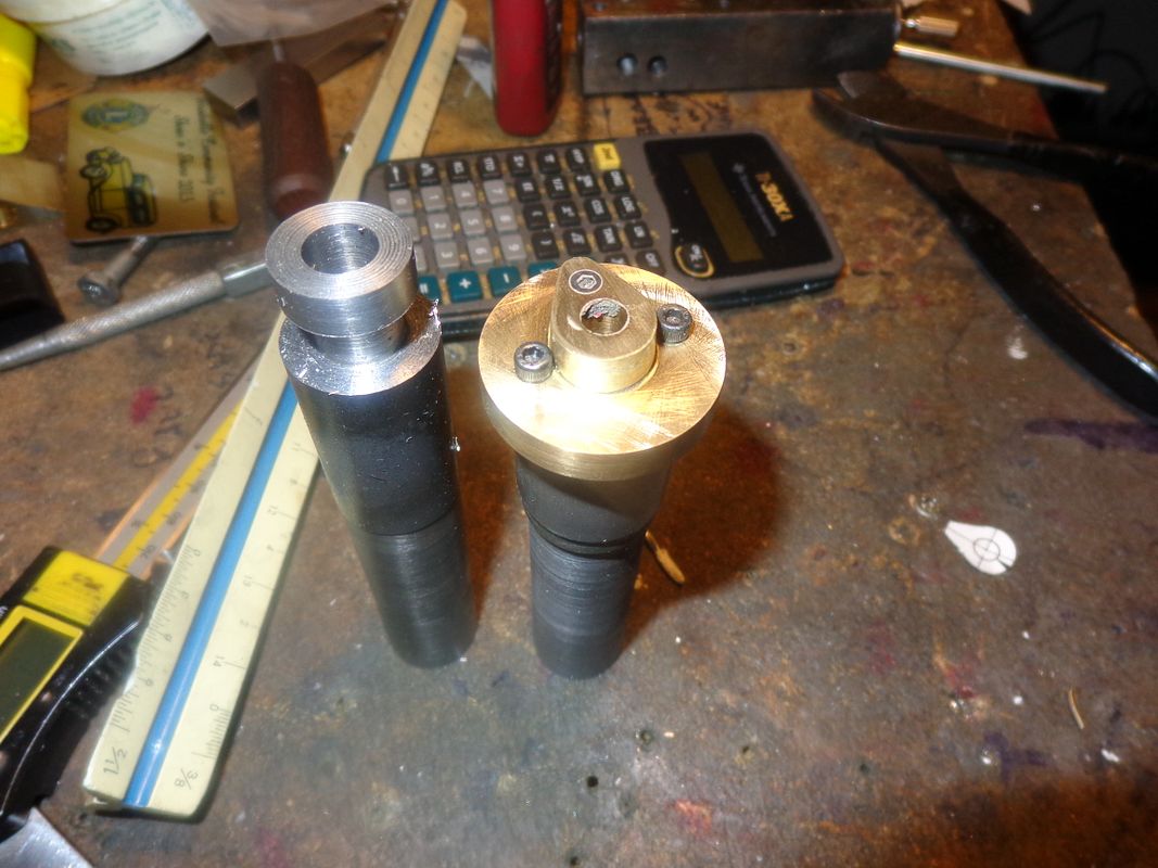
So there we have it---Two infant gears--They haven't got their teeth yet!!! And honest--I didn't know that piece of crud was stuck in the bore of the cam until after I had taken the picture!!! I didn't get a real warm fuzzy feeling about that silver solder job holding the cam to the face of the gear, so I added some insurance.--A #4-40 shcs tapped into the gear and counterbored in the cam. I had a call from a customer needing a quick and nasty sales drawing sometime tomorrow, so I will do that in the morning, and then hopefully add some teeth to these rascals.
 
Darn, you work fast! Your shop must be well organized, at least for you. Nice gears.

Pat W
 
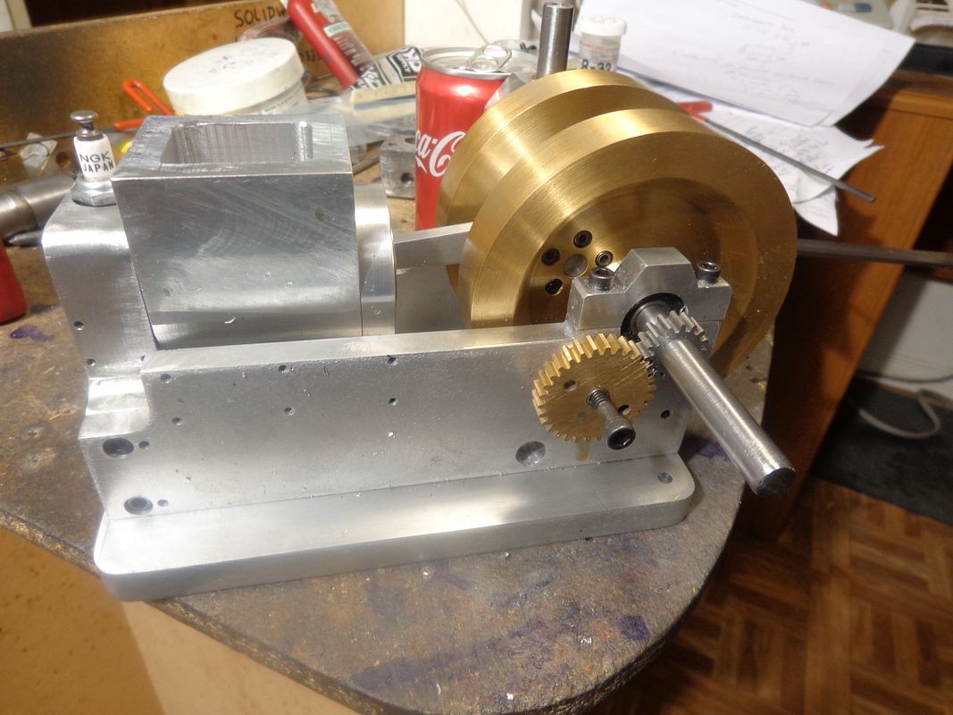
Starnovice. My shop is only seven foot square. It has to be well organized!! Its in a corner of my design office. The gears looked good, didn't they!!! Sadly, Ivan Laws I'm not. The gears meshed perfectly for half a revolution of he brass cam gear. The other half had a terrible bind in it. Somehow, in spite of the care I took, some eccentricity crept into that gear---the pitch circle was not concentric with the 1/4" hole in the center. After a host of wild a##ed ideas, I decided the only fix was to put my gear cutting set up back up on the mill table, and starting on the deepest cut space between the gear teeth, work my way all the way round again. That's 90 turns of the crank---3 between each cut. However, that seems to have corrected the problem, and I didn't have to remake the gear, so I guess "All's well that ends well."
 
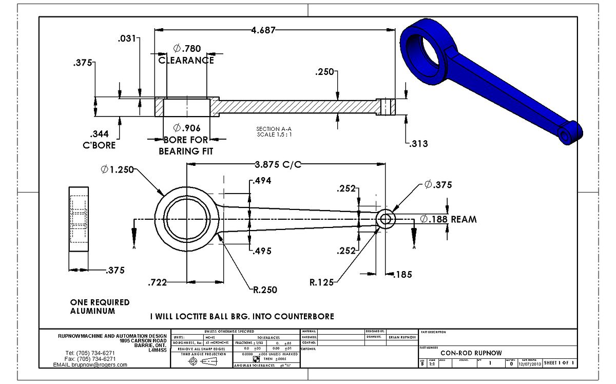
I have edited this drawing by removing the large radius from the 4 corners of the rod, on 12-july-2013. I have deleted the previous drawing that was posted much earlier in the build. When I assembled my engine it became apparent that the large radius was not needed.


View attachment CON-ROD RUPNOW.PDF
 
Hey Brian,
is there any way you go on holiday for a week or so, or slow down on your build.:hDe:

I got into this project cause you said one part a week or so. I'm doing an excellent job with your build but DAMM your going so fast at it that all the guys that agreed to follow your build are simply not following.

if the goal was to build a "race build" I would have like to know about it
I would have walk away..............maybe I should, take all the build parts
and re-cycle them. and do something else

please think about it
 
Luc--no "race build" was intended. I feel a great responsibility when I ask 10 people to build a new, untried engine with me. I would feel terribly bad if I was the cause of 10 people around the world having to change, modify, or redo parts that I might have made a mistake on when designing them. I want their build experience to be as pain free as possible. That is why I am rushing ahead and building parts to the drawings I have posted, so that if any errors show up I can warn people and make appropriate changes to the drawings before they get started on them. I don't expect people to approach this build with the same speed as I am doing. It is not a competition, and I am not trying to make anyone look bad. I am semi retired, and don't have the obligation of going off to work somewhere each day. This allows me to move foreword at a great pace. I can see that everybody involved with this project is moving foreword at their own speed. This is intended to be a FUN build Luc. It also puts me in a position that if people ask questions about the build, I can give them intelligent answerers based on what I have done---Not guesses. Please stay with the project. You have made a great start, and people are watching your progress.---Brian
 
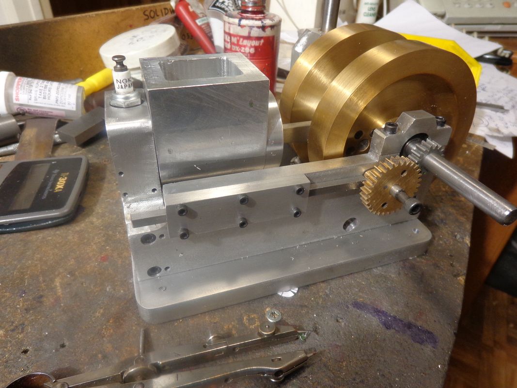
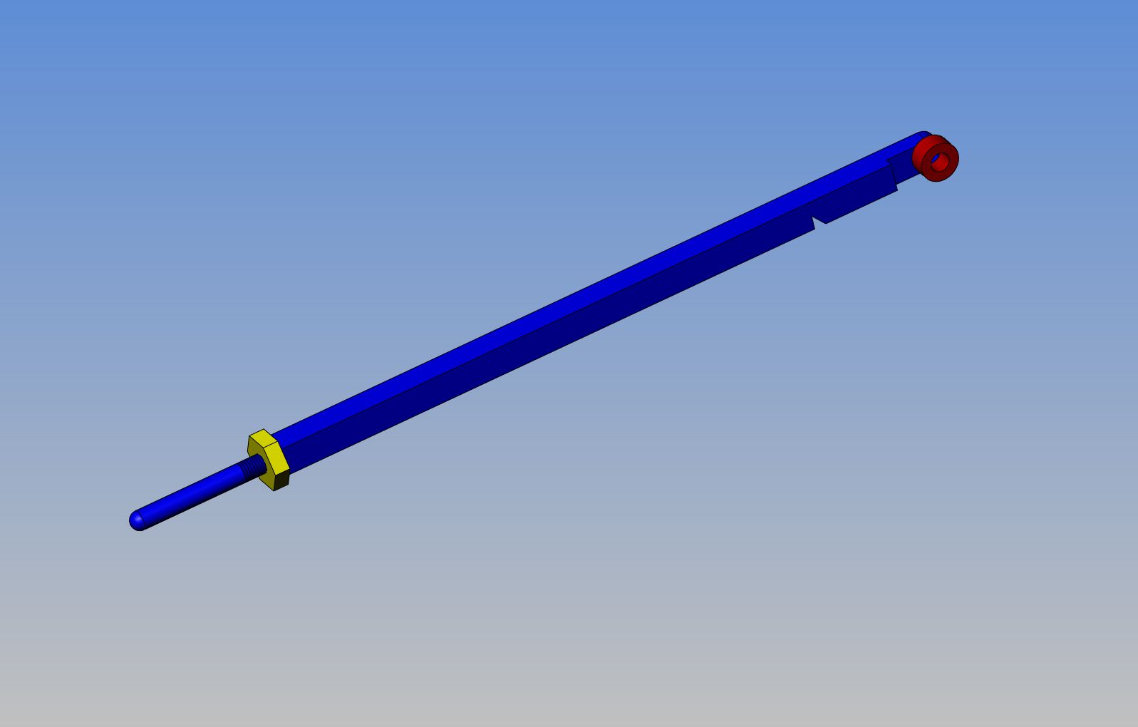
This mornings early offering is a push rod guide. Its neither large nor impressive, but it is one more piece. The 3/16" square bar is just stuck in there to see if it would fit okay!!!
 
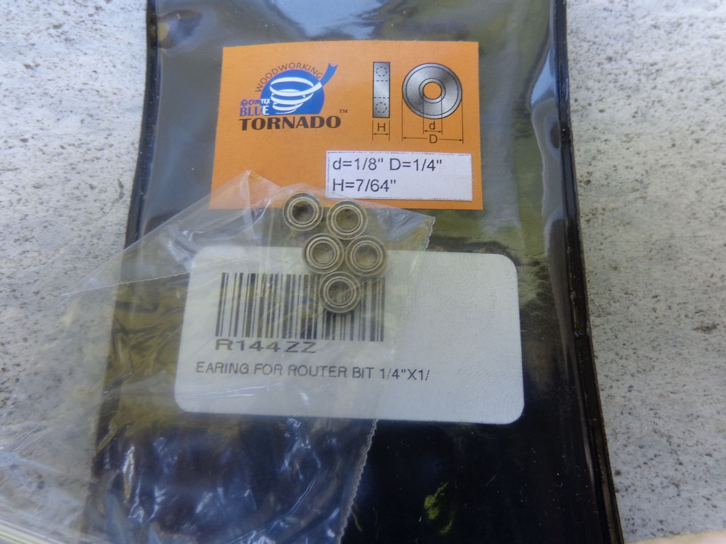
I haven't published anything about the bearing /cam follower on the end of the exhaust valve push-rod before now, because I haven't had a chance to get over to the far end of town where BusyBee Tools are located. I finally got over there this morning, and as I thought, they have router guide bearings that are 1/8" i.d. x 1/4" o.d. x 7/64" thick, 5 to a pack for $10. That's good, considering that I paid $16 for one of similar size three years ago from Canadian bearings.


Latest posts

Back
Top