Rupnow i.c. Engine with governor

Home Model Engine Machinist Forum

Help Support Home Model Engine Machinist Forum:

This site may earn a commission from merchant affiliate links, including eBay, Amazon, and others.
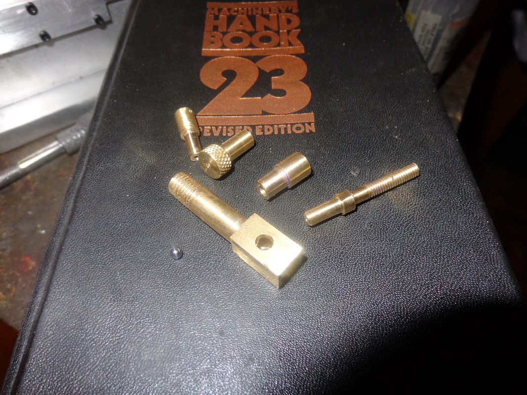
I spent the morning making carburetor bits, then drove about 50 miles north of Barrie to Gravenhurst, Ontario for a swim with my granddaughters. It seems insane to drive 50 miles to go for a swim when I live almost within walking distance of Lake Simcoe, but Lake Simcoe is such a cold lake that my arthritis just about kills me for 3 days after I swim in it!!
 
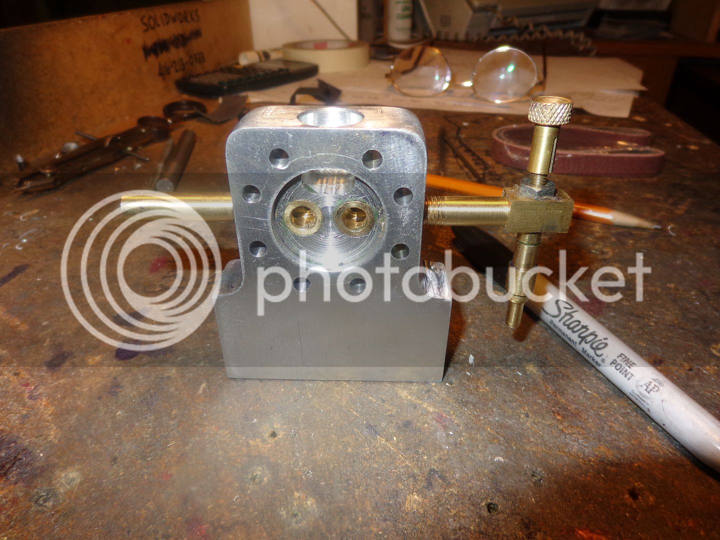
This is the carburetor fully assembled, with the anti-flow back valve in place. Yikes!! I don't think there is anything left to do but valves.:p:p That gooberish looking stuff around the hex nut is a little "seal all" that gets applied to either side of the carb body before the jet is tightened into place.
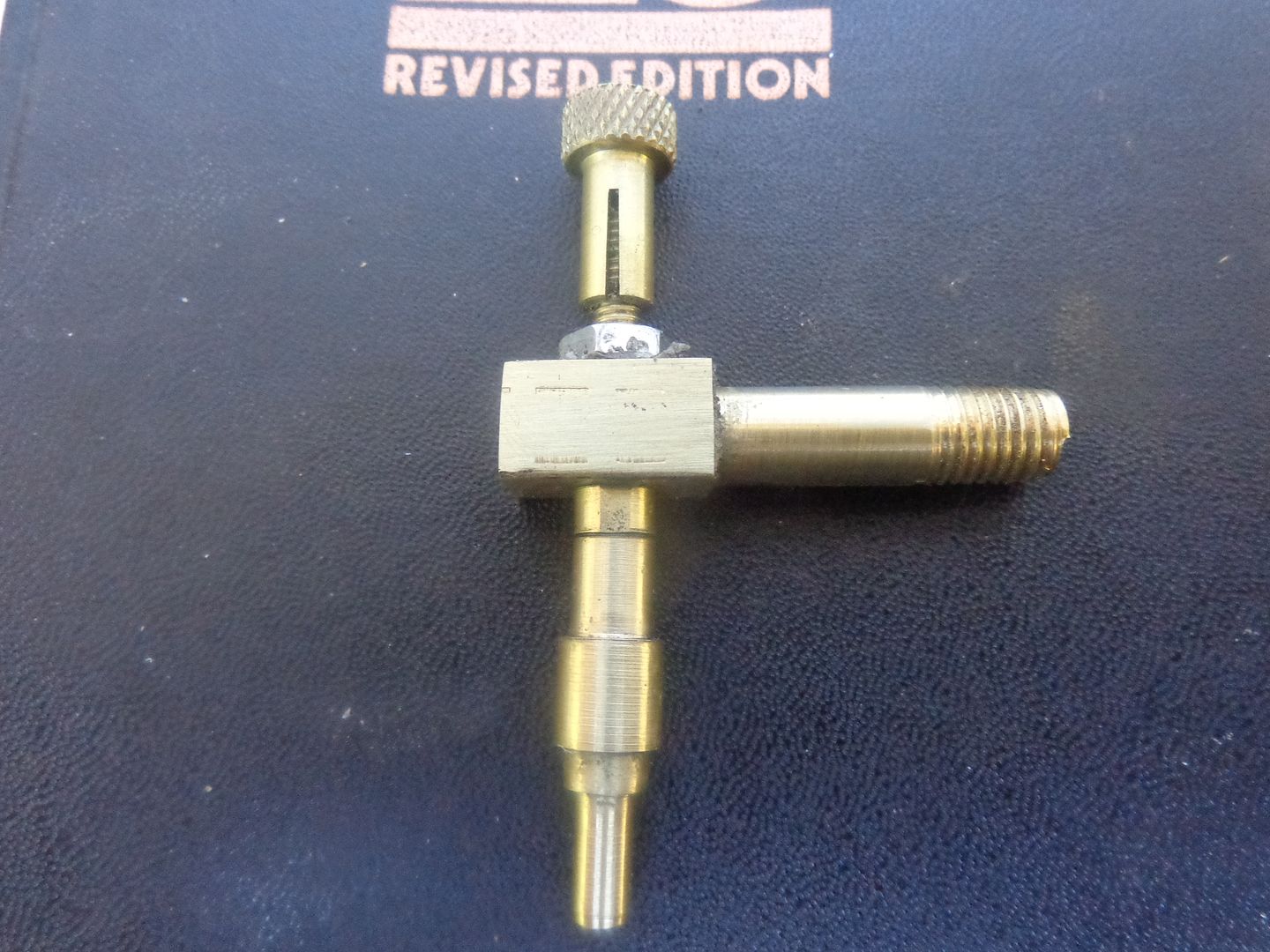
 
This is the carburetor fully assembled, with the anti-flow back valve in place. Yikes!! I don't think there is anything left to do but valves.:p:p That gooberish looking stuff around the hex nut is a little "seal all" that gets applied to either side of the carb body before the jet is tightened into place.
Why not a tiny oring
BTW what did it cost you for the cast for the cylinder??
 
I find that O-rings have a tendency to "squeeze out" when the hex nut is tightened. Remember, there is always a lot of twisting back and forth on that knurled piece at the top that has the needle soldered into it before the engine finally settles in at a "sweet spot" where it no longer needs to be adjusted. The hex nut has to be tight enough to keep the body of the jet from rotating. If it rotates, then the spray hole that faces towards the engine gets turned, and causes problems. I think I paid $5 or $10 for the piece of cast to make the cylinder.--Certainly not more than that.
 
. I think I paid $5 or $10 for the piece of cast to make the cylinder.--Certainly not more than that.[/QUOTE said:
I was quoted 68.00 this morning, and sure enough the bearing were
not stock at Busy Bee:fan:
 
Luc--Send me a private message with your address and I will mail you a bearing. I have 4 left over. $68 for the cast is absolutely out to lunch!! Grey cast iron is much cheaper than that. Try calling "Speedy Metals" or "Metal Supermarket". I'm not 100% sure, but I think it may also known as "Durabar". Perhaps someone else can jump in and clarify that. The full name of what I buy is "Grey pearlitic cast iron", but none of the guys at the machine shop where buy it knew about the "pearlitic". They just said "This is the stuff automotive rebuild shops make cylinder liners out of."
 
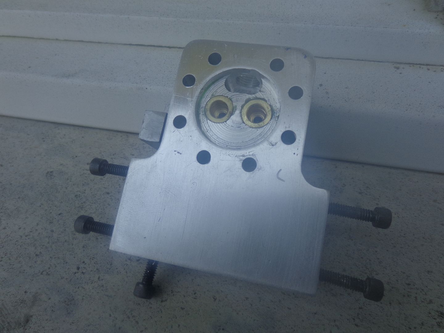
The next thing to build is the valves and cages, however there is one extremely important step that I must perform before that. Remember all of those undersized dowel holes that were drilled in many of the plates, but not in the mating surface that bolted up to it. Now is the time. Right now, with everything seemingly in perfect alignment, and the engine turning over freely, and all the fasteners tightened down. I will use those undersize holes as "guide holes" and drill and ream thru them for 1/8" dowels that go into both plates. Why???---Because without the dowels, I might never get this engine back into such perfect alignment again. I have built other engines to this stage, and then disassembled them without doweling them first. There is enough "tolerance/clearance" on all of the bolt holes that the engine becomes a total pig when reassembled, with binds popping up in places that ran perfectly free before the engine was taken apart.---Brian
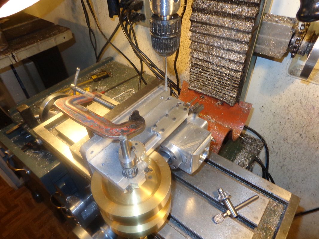
 
The next thing to build is the valves and cages, however there is one extremely important step that I must perform before that. Remember all of those undersized dowel holes that were drilled in many of the plates, but not in the mating surface that bolted up to it. Now is the time. Right now, with everything seemingly in perfect alignment, and the engine turning over freely, and all the fasteners tightened down. I will use those undersize holes as "guide holes" and drill and ream thru them for 1/8" dowels that go into both plates. Why???---Because without the dowels, I might never get this engine back into such perfect alignment again. I have built other engines to this stage, and then disassembled them without doweling them first. There is enough "tolerance/clearance" on all of the bolt holes that the engine becomes a total pig when reassembled, with binds popping up in places that ran perfectly free before the engine was taken apart.---Brian

That sounds like wisdom that only real life experience brings! I've had that issue with hydraulic clamping fixtures and other related things... You never forget those hard learned lessons! I haven't thought about that in my limited engine making but I'll certainly store that useful tidbit as I have learned this lesson elsewhere!
 
Hi Brian, are you using solid dowels or the split "spring" type dowels

Andrew
 
Brian,
I was abble to get some bearing this morning metric
3x8x4 mm
the plate for the governor are you going to CNC them
 
This is another "in process" shot. I have just finished putting in all of the dowel holes. A word of WARNING!!! The dowels which go in from the bottom of the baseplate can all be pushed in flush with the bottom of the baseplate. (I drilled and reamed the holes a total of 1" deep for 1" long dowels.) HOWEVER--The dowels that go thru the sideplates into the cylinder head must be left at least 3/16" longer than the hole depth. Why??--Because if you push them in flush, you will never be able to get them out again and you will be unable to remove the cylinder head. If this was a full size industrial machine, the dowels would be larger and have an internal thread so that a dowel puller could be used to remove them. At this scale, however, the dowels are too small in diameter for a threaded puller hole, so they must have enough material setting "proud" of the outer plate to be gripped with a pair of pliers and removed.
 
The valve cages are completed and installed, although I haven't drilled the ports in the cylinder head yet that break through into the sides of the valve cages. I stepped out into the back yard to take this picture, and going from my air conditioned shop to 95 degrees F outside immediately made my camera fog up. I will build the valves and drill the ports tomorrow.
 
Nothing much left but them nasty old valves. This is where Brian generally falls on his butt!!! I will attempt to start and run the engine without the governor.--That's assuming I can convince the little engine Gods to give me compression tomorrow. I put the Viton ring on the piston today and slid the piston into the cylinder---All kinds of compression on ring alone.
 
Almost ready for brooom brooom brooom. Looks great.
 
Both valves are finished now, except for trimming to length and putting an 0.040 cross hole through the ends for a retaining pin. I use 3/8" cold rolled steel, and turn the valve stem down to 0.127" diameter for about the first 5/16", then I record my crossfeed dial setting and turn down another 5/16". I keep doing this until the full length of the stem portion is turned. Turning it in this manner prevents all the deflection you would normally get if you turned down the entire length in successive passes. I set my crossfeed over to the desired angle, and make many small passes at the abrupt shoulder of the turndown until the actual valve "face" is fully formed at the angle I have dialed in. I then use 200 grit emery cloth to bring the stem down to the final .125" size. I have the lathe turning at about 1000 rpm when I do this. This is a very tricky business, because there is no way to measure how much you are taking off with the emery paper, and you DO NOT WANT an undersize valve stem. I generally hold a fold of the paper between my thumb and finger with the "stem" gripped between two abrasive sides and with the lathe turning at 1000 rpm and slide the emery paper back and forth on the stem for a slow count to 20, then shut off the lathe and try the stem for fit into the valve cage hole. I might end up shutting the lathe off and turning it back on a dozen times until the fit is "perfect". I like to leave a three inch (approximate) "handle" on the valve, as seen in the picture, because it gives me something to hold onto when lapping the valve into the seat in the valve cage. I first use some 350 grit oil based lapping compound on the face of the valve and while pressing the valve face against the "seat" I twirl it back and forth with my fingers, about 100 times. Not full rotations, just back and forth, and every 25 "twirls" I move the cylinder head around about 90 degrees with the other hand which is holding it. DO NOT get lapping compound on the valve stem!!! I then repeat the preceding with 400 grit, then one last time with 600 grit. When I am finished and all of the lapping compound is cleaned away with varsol, I hold the valve closed and try to blow through the exhaust pipe or the carb air intake. If you can blow any air at all, then its not lapped properly and the lapping procedure must be repeated. Now I will cut the "handles" off of the valves and drill the cross holes for the retainers. And Oh Yeah---one last thing. Once the valves are lapped, don't mix them up!! the lapped face is an exact match ONLY to the seat it was lapped in!!!

 
Last edited:
Back
Top