You are using an out of date browser. It may not display this or other websites correctly.
You should upgrade or use an alternative browser.
You should upgrade or use an alternative browser.
Rupnow i.c. Engine with governor
- Thread starter Brian Rupnow
- Start date

Help Support Home Model Engine Machinist Forum:
This site may earn a commission from merchant affiliate
links, including eBay, Amazon, and others.
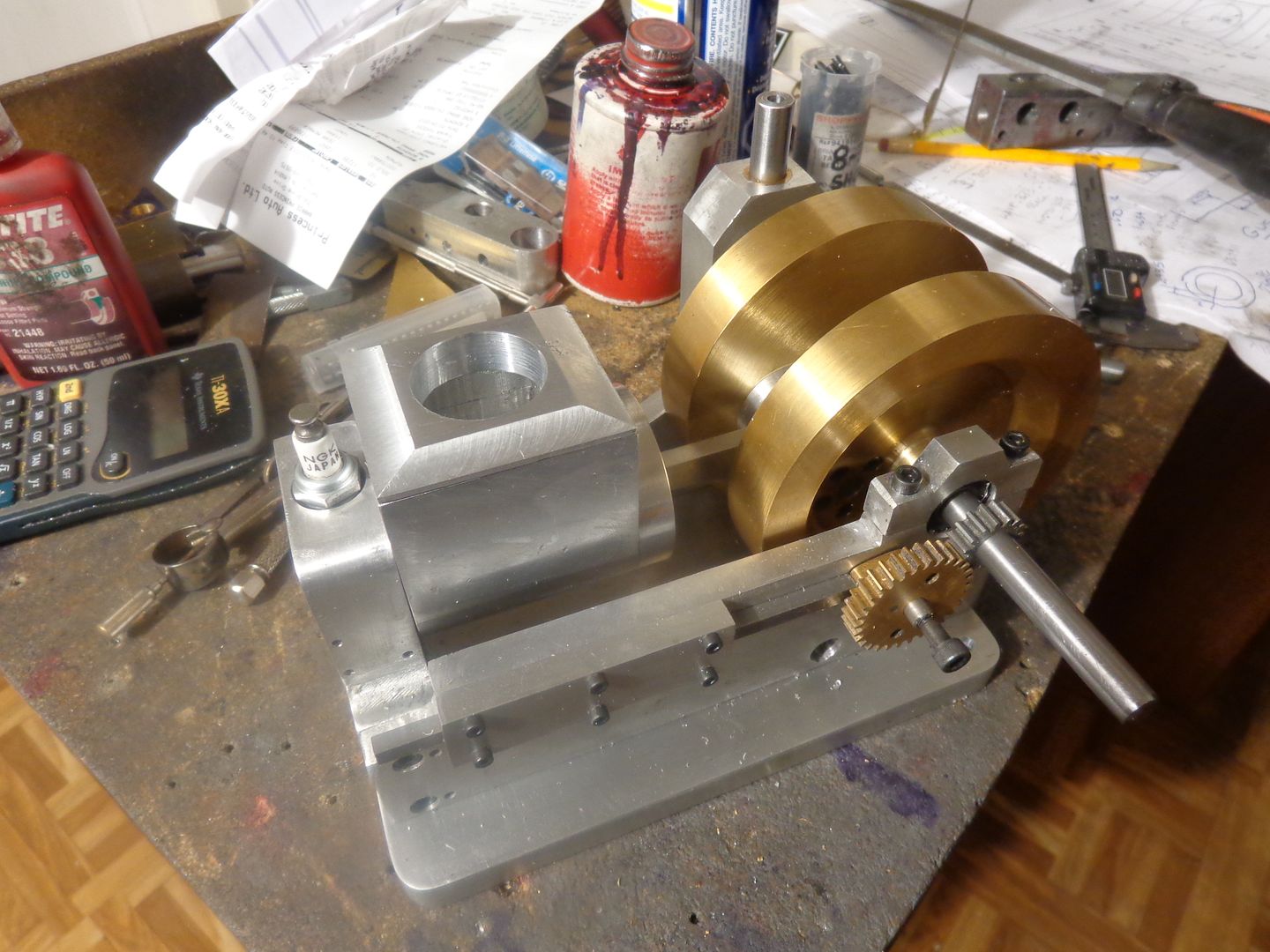
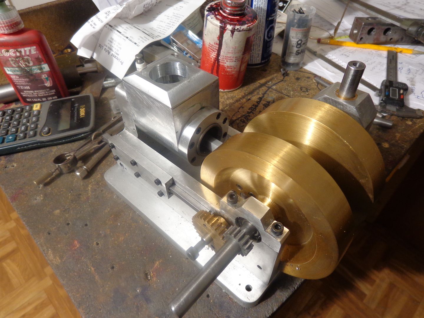
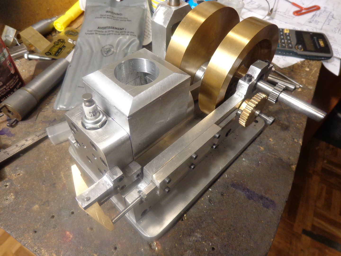
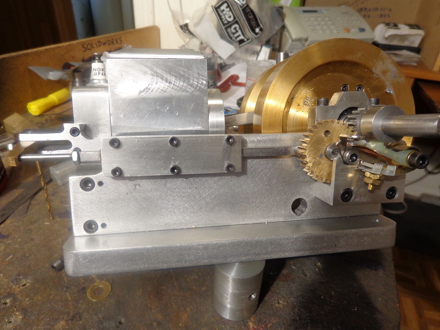
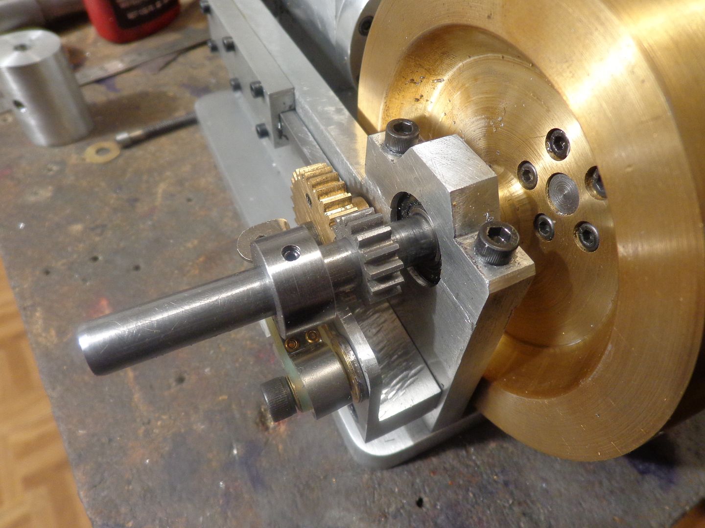
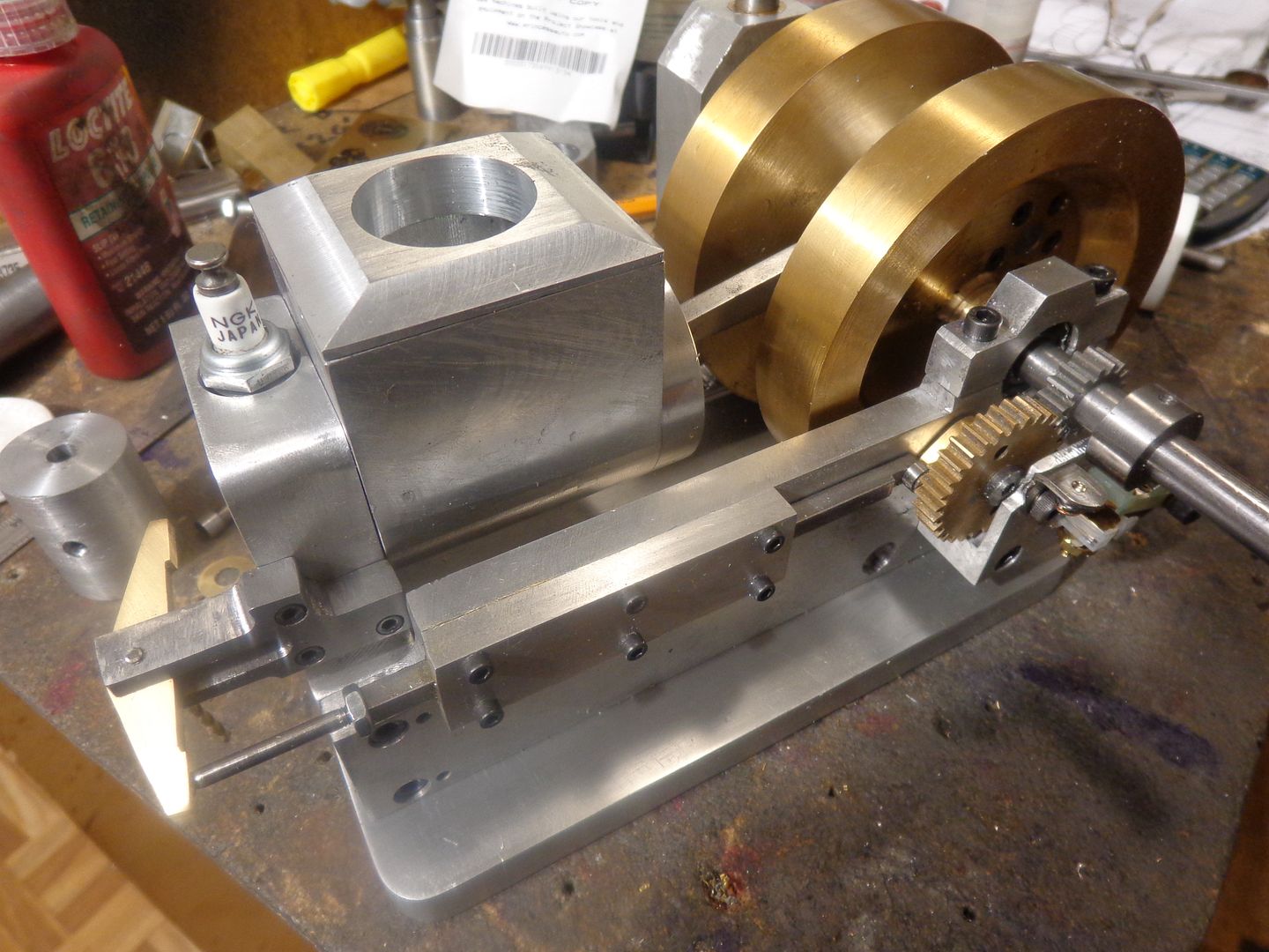
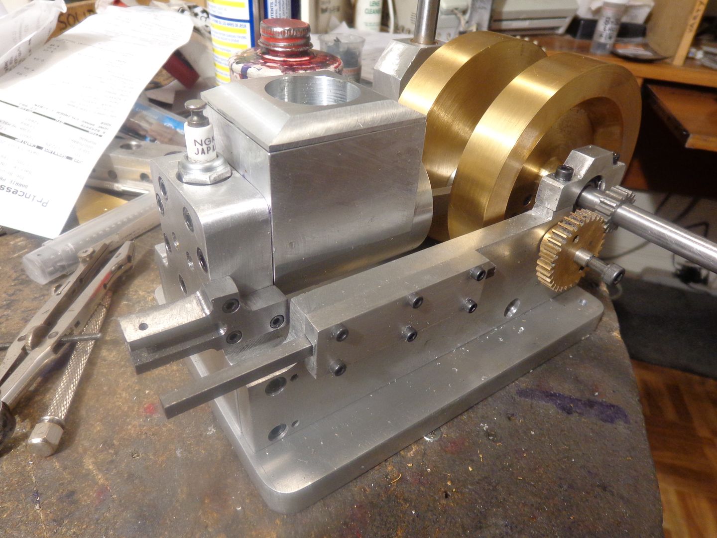
I am rapidly running out of fun, easy, no-brainer stuff to build. Although the hokey crankshaft seems a bit weird at first, it seems to be easy to make and doesn't appear to have any more run out than the "normal" crankshafts I have built on all my other engines. I really don't want to invest a lot more time in the governor until I convince myself that the engine runs okay in "normal 4 cycle engine" mode. I am going to use the same carb setup that I used on my last hit and miss engine. I guess I will start tomorrow on the rocker arm and the rather strange shaped piece that supports it. Monday I will go buy a set of points and build the support block for them and make an ignition cam. Nobody has asked me yet, but the small gear is not held to the crankshaft by magic---Its cross drilled and anchored with a 1/16" split pin thru it and the crankshaft. Looking at it in hindsight, I had lots of room on either side of the small gear for a hub and setscrews, but even I get locked into paradigms.--That gear worked just fine on the last hit and miss engine I built, which also had a 3/8" crankshaft, so I'll use the same again.--Yeah, right!!! The only problem with a gear this size is that the root diameter of the gear doesn't really leave enough meat for a proper hub and keyway or set screws, and if I increase the size of this gear, then I have to increase the size of the cam gear, and yada yada yada!!! It'll be fine!! Notice how I am skirting around the issue of valve cages and valves.---Its like having a tooth extracted---You put it off for as long as you can---
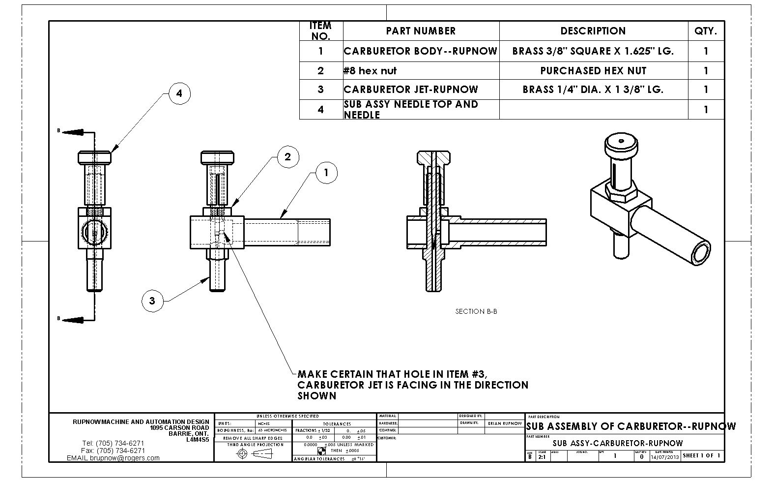
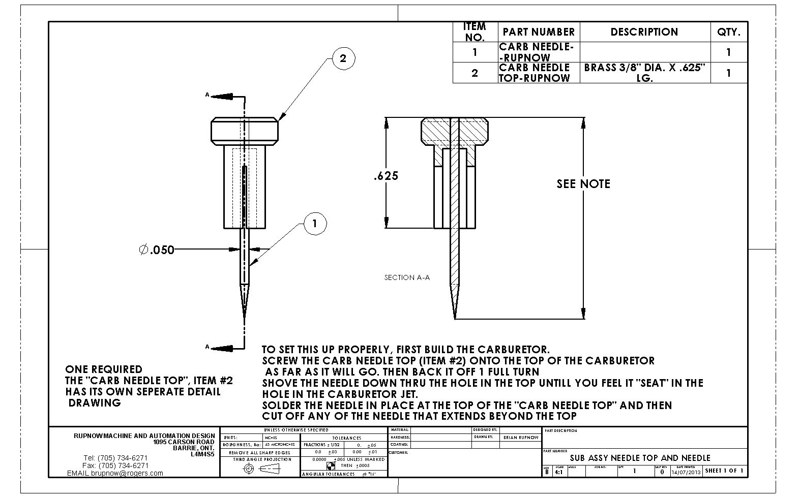
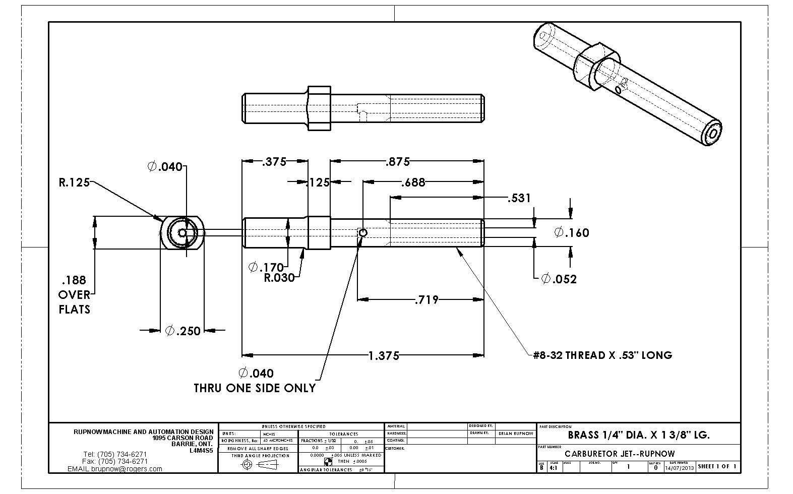
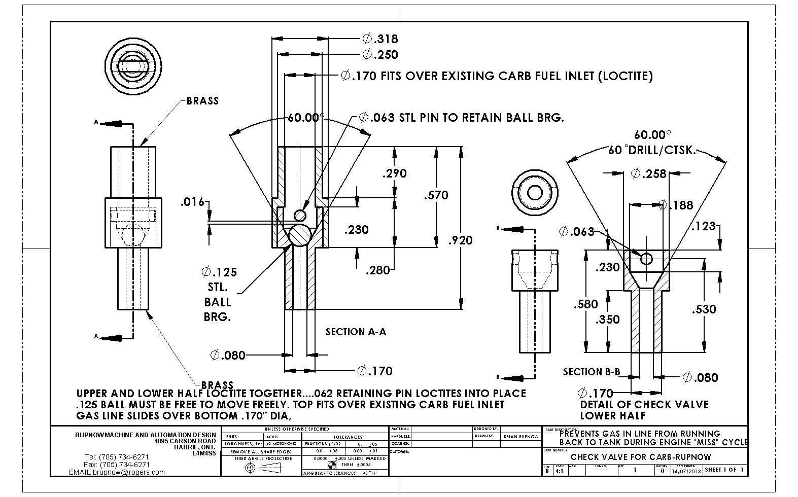
We may not be at 100% detailed yet, but we must be getting close. I think the carb is all that's left to do.
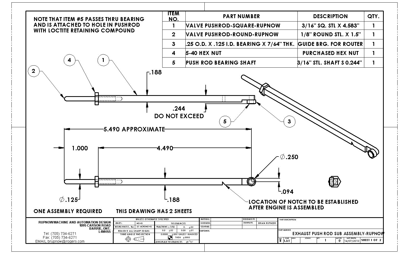
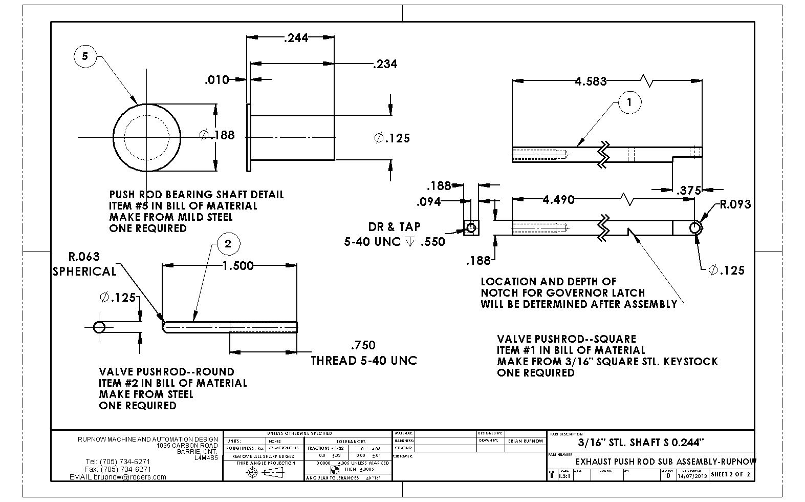
View attachment EXHAUST PUSH ROD SUB ASSEMBLY-RUPNOW.PDF


View attachment EXHAUST PUSH ROD SUB ASSEMBLY-RUPNOW.PDF
Last edited:
![DreamPlan Home Design and Landscaping Software Free for Windows [PC Download]](https://m.media-amazon.com/images/I/51kvZH2dVLL._SL500_.jpg)
$0.00
DreamPlan Home Design and Landscaping Software Free for Windows [PC Download]
Amazon.com Services LLC

$40.02
$49.99
Becker CAD 12 3D - professional CAD software for 2D + 3D design and modelling - for 3 PCs - 100% compatible with AutoCAD
momox Shop

$29.95
Competition Engine Building: Advanced Engine Design and Assembly Techniques (Pro Series)
Amazon.com Services LLC

$24.99
$34.99
Bowl Sander Tool Kit w/Dual Bearing Head & Hardwood Handle | 42PC Wood Sander Set | 2" Hook & Loop Sanding Disc Sandpaper Assortment | 1/4" Mandrel Bowl Sander for Woodturning | Wood Lathe Tools
Peachtree Woodworking Supply Inc
And the only machining that's going to happen here today, is the "Rocker Arm Mount". I don't think "Tricky Bugga" would be an overstatement!!! I did have a last minute change of heart and made the pivot hole .093" diameter instead of the .125 the drawing originally called for. I will fix up the drawings later today or tomorrow.

This drawing revised 14-july-2013--Pivot hole diameter was previously .125", HAS CHANGED TO .093".
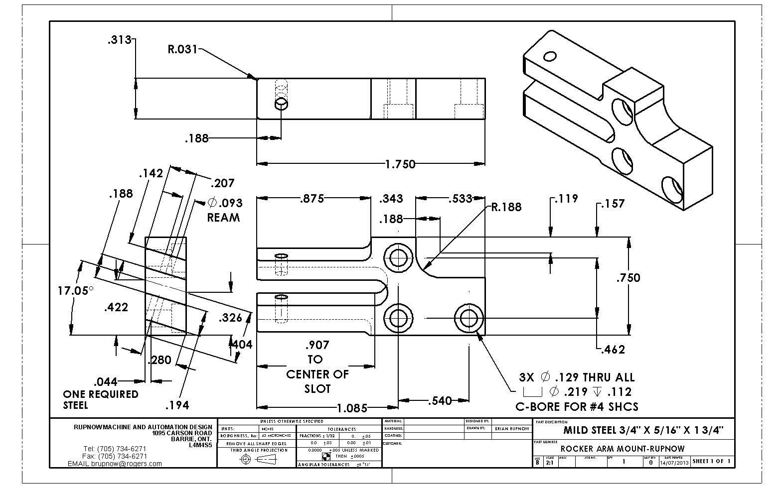
View attachment ROCKER ARM MOUNT-RUPNOW.PDF

View attachment ROCKER ARM MOUNT-RUPNOW.PDF
Last edited:
This drawing revised 14-july 2013--pivot hole diameter was previously .125---has now changed to .093"
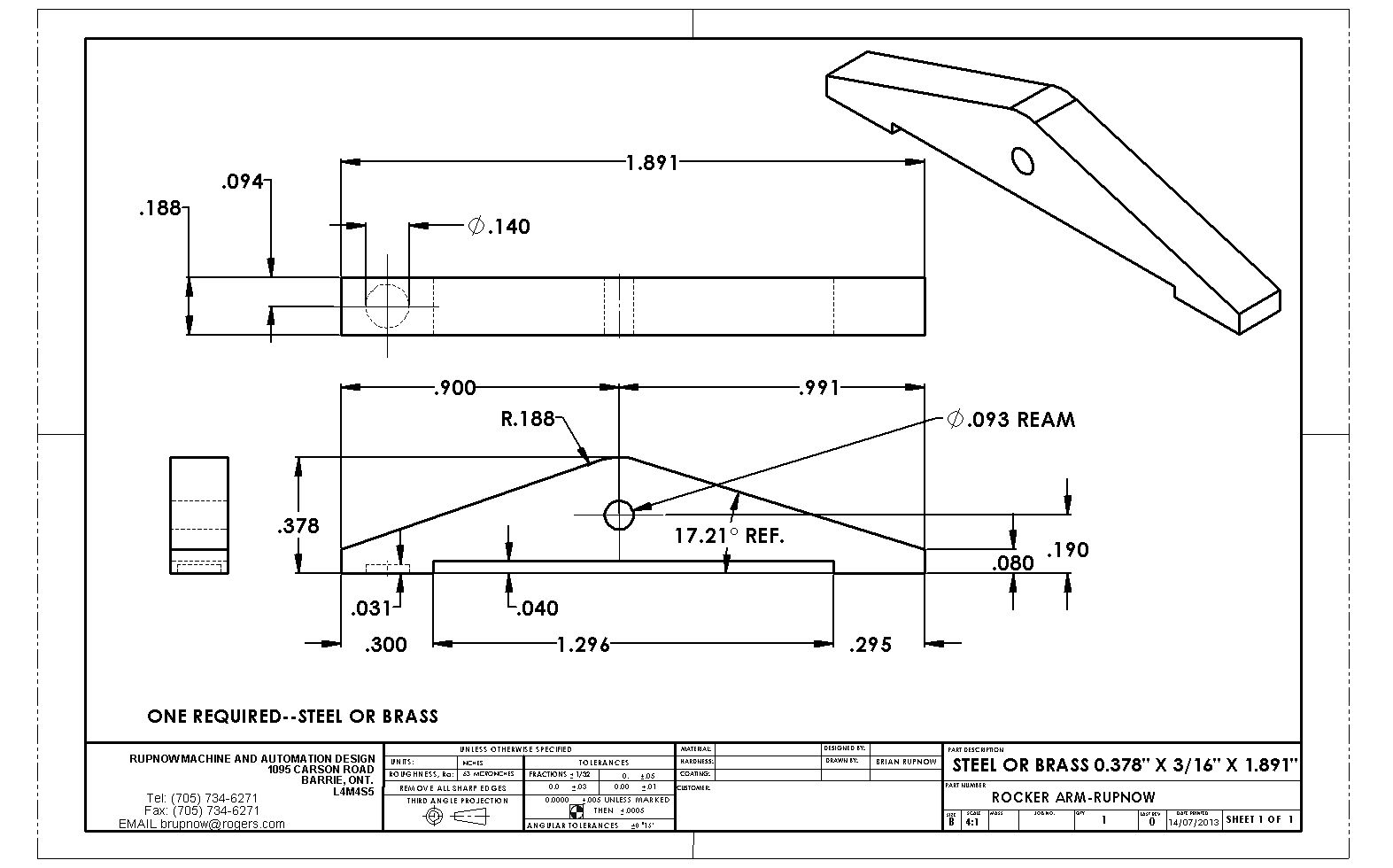
View attachment ROCKER ARM-RUPNOW.PDF

View attachment ROCKER ARM-RUPNOW.PDF
Something I noticed during assembly of the pushrod this afternoon---I was quite emphatic about the overall width of the pushrod with the bearing installed not exceed .244".-I put a big note to that effect on the drawing. My reasoning was that since the cam is only .250" thick, I needed clearance between the face of the bearing and the inner face of the gear. BIG HEADSLAP FOR ME--- If I'm a bit crowded for room, I can always put a .020" or .030" spacer between the cam and the sideframe. This would require a slight counterbore in the outward face of the gear if using a 1/2" shoulderbolt to hold the cam gear in place, but there is lots of room. See, its the finished position of the cam gear that determined where the crankshaft gear gets placed.
If we plan on making any sparks, we're going to need one of these to go with our Chrysler ignition points.
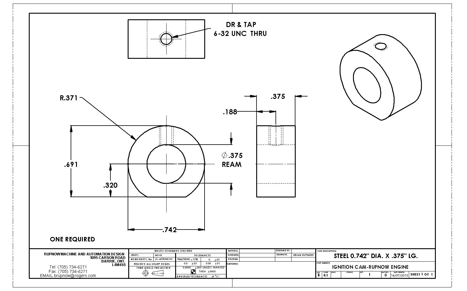
View attachment IGNITION CAM-RUPNOW ENGINE.PDF

View attachment IGNITION CAM-RUPNOW ENGINE.PDF
Last edited:
Andrew, I would certainly welcome you to the build. This has proven to be a most interesting engine, and I am closing in on the home stretch of mine. I supposedly have 5 other people around the world who are building this engine with me, but I'm not seeing too many posts from them. Have you built an i.c. engine before?---Brian
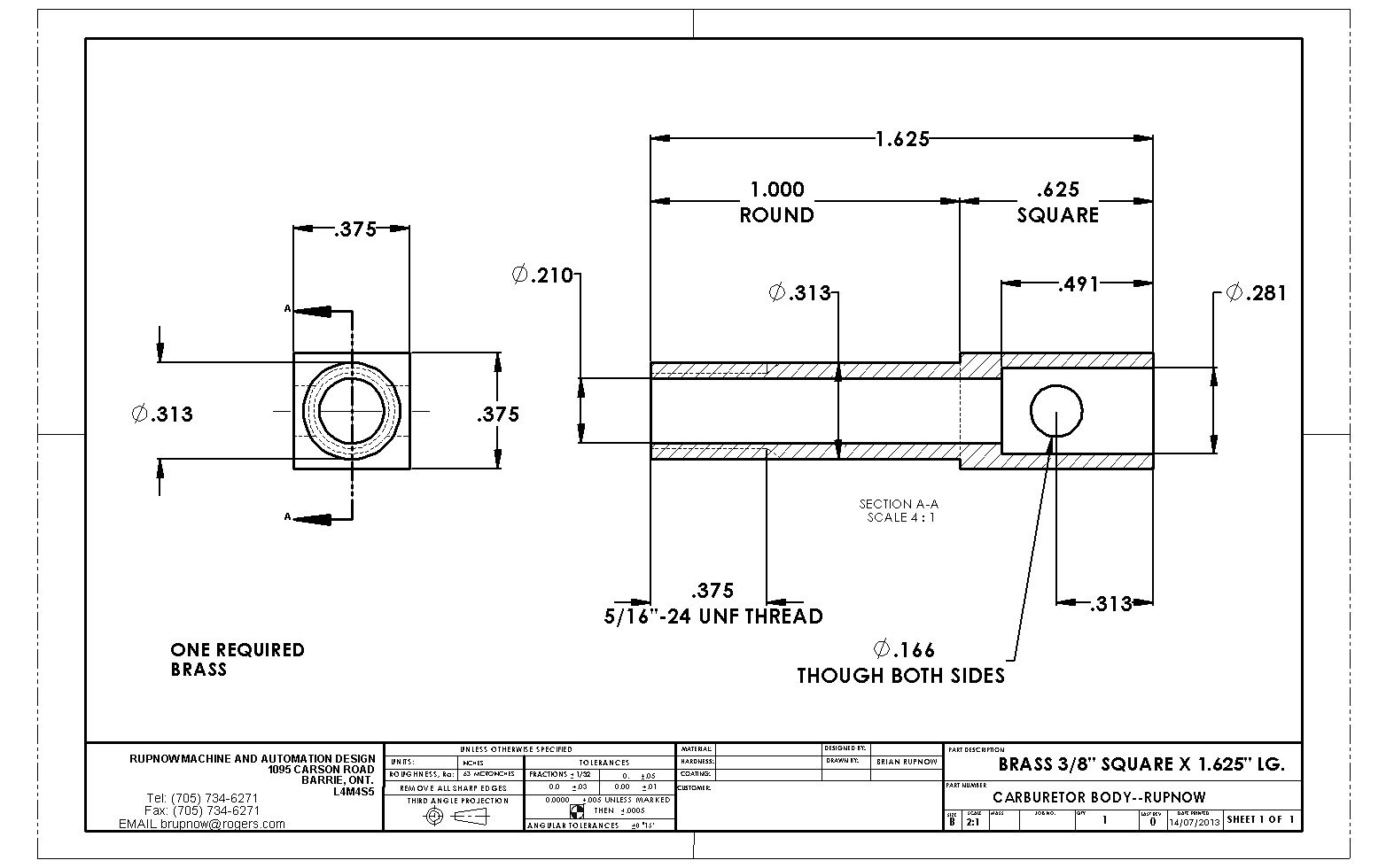
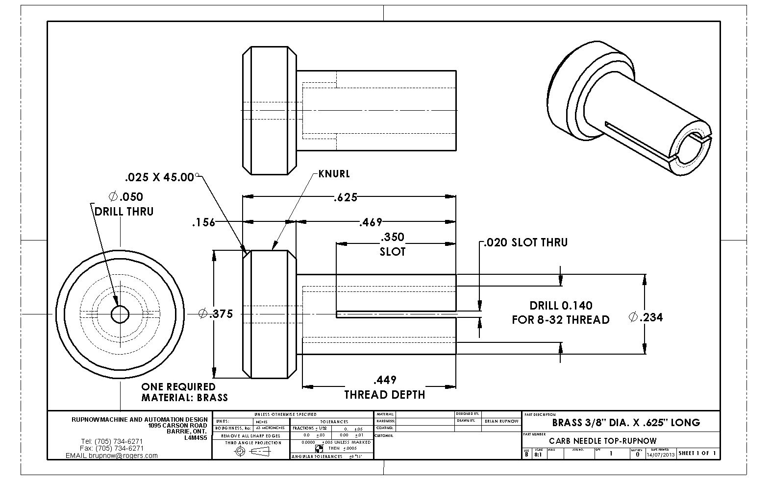
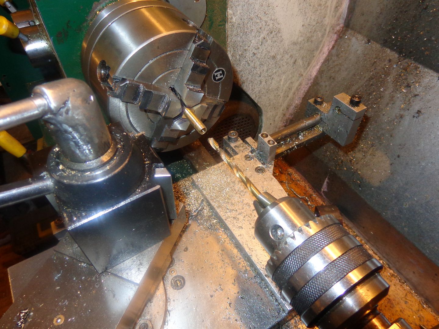
Someone emailed me and asked why I didn't show more "set-up" shots rather than just finished parts. When I first started posting 5 years ago, I used to show a lot of "set-up" shots, because everything was new to me and a proper set up was pretty exciting stuff. Now after 5 years of engine building, the set-ups have became such a normal part of the entire machining process that I don't generally do "set-up" shots anymore. At any rate---Here is a set up shot, showing the carb body in the 4 jaw on my lathe. I actually machined the 5/16" diameter using the cut off tool so I would have a good square shoulder where the round transitions into the square section. I have threaded the round part 5/16"-24 and just drilled a .210" hole full length of the part. I will finish it up tomorrow.

Similar threads
- Replies
- 95
- Views
- 12K
- Replies
- 28
- Views
- 7K


