Rupnow i.c. Engine with governor

Home Model Engine Machinist Forum

Help Support Home Model Engine Machinist Forum:

This site may earn a commission from merchant affiliate links, including eBay, Amazon, and others.
Very nice Brian! Thanks for taking us along for the ride and further thanks for sharing the design!
 
This morning I am going to cover how to do the valve timing on this engine. We are going to be looking at the non-governor side of this engine, with the flywheels on the right and the cylinder sticking out towards the left. This engine is going to rotate clockwise when viewed like this, and I will tell you why later. Remove the 4 bolts which hold the crankshaft bearing caps on, but do not yet remove the bearing caps themselves. Rotate the flywheels clockwise until the piston is travelling from top dead center towards bottom dead center. Stop when the piston skirt (which you can easily see) is about 1/8" from its end of outward travel. Using a screwdriver under each flywheel, lift the crankshaft and bearing caps straight up until the gear on the crankshaft clears the gear on the camshaft. Rotate the camshaft gear counter-clockwise by hand until the cam just begins to lift the exhaust valve. You will feel it when the cam actuated pushrod begins to meet the resistance of the spring which holds the exhaust valve closed.) At this point, lower the crankshaft back into place carefully. Make sure that the piston is still about 1/8" from bottom dead center on the downstroke. Rebolt the bearing caps and rotate the crankshaft slowly clockwise. This is a four cycle engine, so the valve will lift only on every second revolution of the crankshaft. As the piston approaches bdc, it will get about 1/8" from the end of travel, and at that time the cam will begin to open the exhaust valve. The piston travels past bdc and begins its exhaust stroke towards tdc, and the valve should fully open and then close just before the exhaust stroke (travelling towards TDC) ends. The piston travels past top dead center and begins what would be the intake stroke. It travels from top dead center to bottom dead center on the intake stroke, with the exhaust valve remaining closed. Then it travels from bottom dead center to top dead center on the compression stroke with the exhaust valve still closed. At top dead center a spark occurs igniting the fuel mixture, and the piston travels towards bottom dead center on the power stroke. Just before it reaches the bottom of its power stroke the exhaust valve begins to open again for the exhaust stroke. Then the sequence repeats itself.--Why do we want it to rotate in this direction---Because unless you have a model aeroplane starter gun, or can always start your engine by hand, you will be using your electric drill as a "starter".--If you rotate things in the opposite direction, the chuck on the drill tends to loosen itself off and your "starter bit" will come loose in the drill chuck!!!
 
To set the ignition timing, rotate the flywheels clockwise (again looking at the engine from the "non-governor side) until the piston is at top dead center. It doesn't matter if its on the exhaust stroke or on the compression stroke. Loosen off the set screw in the ignition cam, and rotate it clockwise until the ignition points just begin to open--(again, you will feel the resistance when the cam contacts the rubbing block on the ignition points.). Lock down the set screw. Now we will get a spark every time the piston is at top dead center. If the piston is on the compression stroke, the spark will ignite the fuel and the engine will fire. If the piston is on the exhaust stroke, the ignition will fire then too, but since there is no fuel to ignite on that stroke, the spark won't effect anything.
 
Assuming that you valves are seating properly, and your piston ring is installed and working, when the piston moves from top dead center to bottom dead center during the intake stroke, a considerable amount of vacuum should be created in the cylinder. This is when your "atmospheric intake valve" is supposed to open. As stated before, this is an extremely "dicey" adjustment. The spring has to be strong enough to close the valve, but light enough to be operated by "vacuum". Now some engine builders will tell you that this judgement call can be made while the engine is being turned over by hand. My experience has been that you can turn the engine over till the cows come home, and never see the damned valve move!! That's part of the reason I like to drive the engine with an electric motor. Make your "best guess" for valve spring length, hook up the electric motor, and let things roll. If you see the valve dancing up and down, you're golden. If the valve doesn't appear to move, remove the valve, cut one coil from the valve spring and reinstall. WARNING--WARNING--Make sure your piston is at top dead center while doing this, or there is a good possibility you will chase the valve out of sight and it will fall into the cylinder, requiring you to disassemble the whole engine to get the valve back.---Don't ask me how I know!!! After removal of one coil, try the electric motor again. Keep on removing one coil at a time until you see that valve start to dance as the motor turns the engine over at a good clip, say about 300 to 400 RPM. Don't expect to see MUCH movement--the valve may only open 1/16" or less, but it does have to open. On the current engine I am building I had to remove either 3 or 4 coils (can't remember which) from the half length spring that I started with before the valve began to move. Also, be aware that the valve stem must slide very freely in its guide, but not so freely that it leaks a lot of air. There are a lot of "judgement calls" involved here, that can only be learned by experience, and paying your dues in frustration..--Of course, it goes without saying that your sparkplug must be installed during this operation.
 
Last edited:
I have been herding cats all morning, trying to get a good long consistent run from the engine. I have had a couple of good two minute blasts from the engine, and then just as I was about to run in and get my camera, it would die again. /$"%!!! Right now, I have hit the wall for today. Things are very tight in the area where the shoulder bolt holds the cam gear in place, and I have shaved away the head of the shoulder bolt until I can no longer get my Allen wrench to engage the formed drive hole in the end of the shoulder bolt, and I can't get another bolt until tomorrow. The cam gear with the cam on it is 1/2" thick, and the shoulder bolt is 1/2" long under the head. I ended up putting a .020" deep counterbore in the outer face of the cam gear to let the head of the bolt "set in" a bit so it doesn't pinch the cam gear against the sideplate, but right now I am finding that the counterclockwise motion of the cam gear is unscrewing the shoulder bolt because I can't get a good enough grip on the head of the bolt to tighten it. I have been "making do" with a very scary fuel container, so I may rob the fuel tank off the Atkinson until I get this engine sorted out.
 
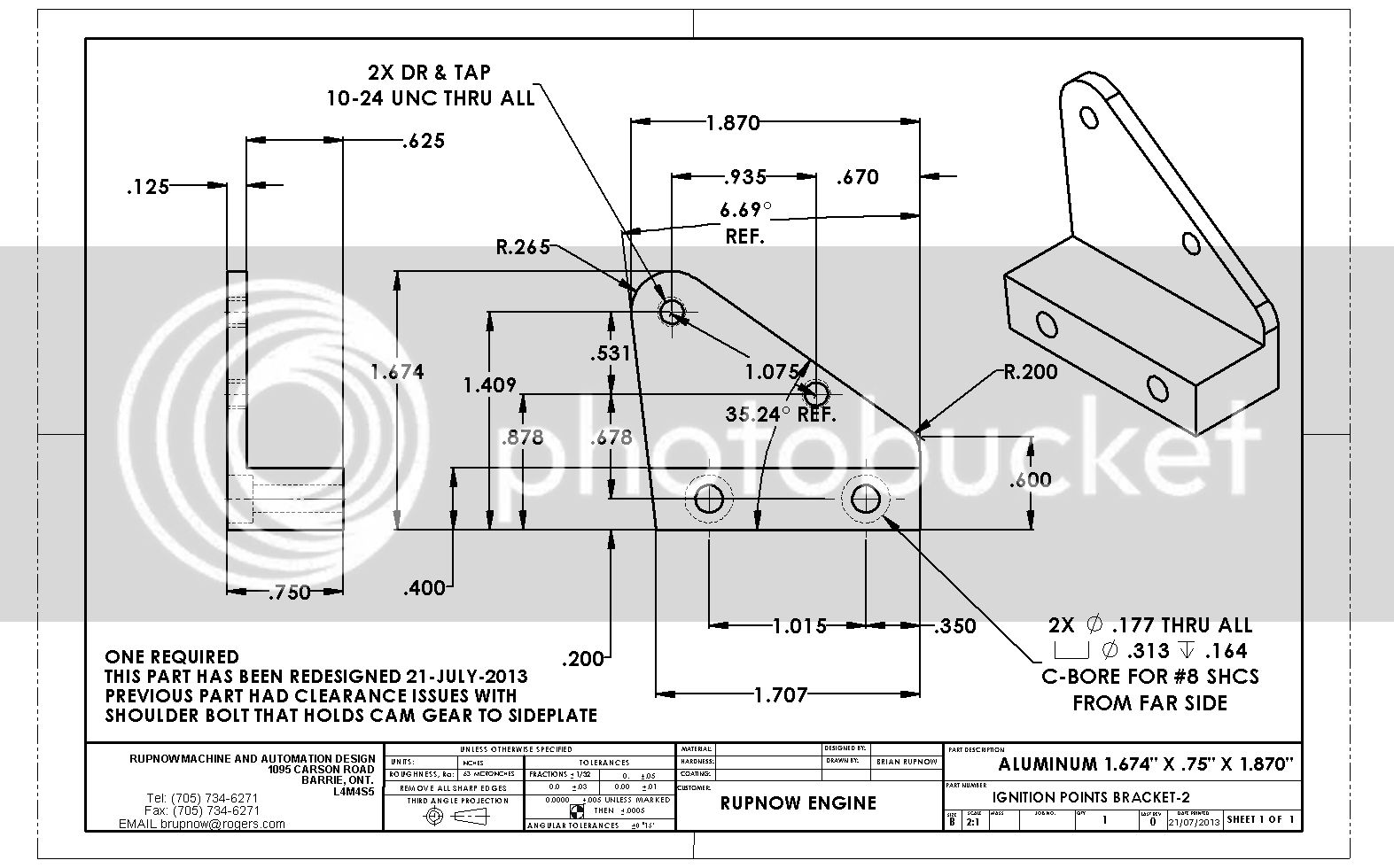
I have just redesigned the "IGNITION POINTS MOUNTING PLATE"--If you haven't built it already, then don't. I will make the new one tomorrow and mount it, then put up a new drawing.
 
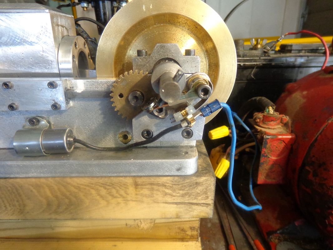
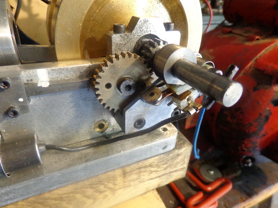
The ignition points bracket has been redesigned and remade. The reason for that is that it completely covered the head of the shoulder bolt which holds the cam gear to the sideplate, and there were simply too many things all trying to occupy the same space. My bad---Sorry 'bout that. What I have done is effectively "rotate" the ignition points counter-clockwise until they completely cleared the head of the shoulder bolt, then made a new bracket to fit that position. It picks up the same holes in the sideplate as the previous bracket did. I have made and installed the new bracket this afternoon, so I am sure it fits alright.


View attachment IGNITION POINTS BRACKET-2.PDF
 
Last edited:
Sooooo---Lets take stock here. I know of 5 people internationally who have said they intend to build this engine. We have Luc, a fellow Canadian from Ottawa, Canada, Cogsy from Australia, Smithers from Tasmania, Canman from England, and RiverGypsy from (I think) England. Pat H from California USA has expressed interest, but I don't think he has actually started a build. I'm curious---Has anybody built the air cooled cylinder yet? I have built the water cooled version, and although it seems like a lot of machining, it looks good and holds water. I know Luc is making progress, and Cogsy has shown us a pair of nice steel flywheels. Luc--did you find a cheaper source for grey cast iron? Do any of you fellows who are CNCing the parts have assemblies yet? I know that the engine runs now, (which is always a bit of a relief on a new design.) I hope to have mine totally sorted out this week so that I can proceed with the governor part of the build. So far, out of all the parts built, I have only had to redesign one part, the ignition point bracket, and I have posted a new drawing of it and machined and installed the new part on my machine and posted pictures of it in place. Tomorrow when I get another shoulder bolt for the cam gear I have high hopes for a better, longer run.---Brian
 
Hi Brian
just came back from shopping in state Harb:Dur Freight of course
I got some pictures I'll be posting in a few minutes I took picture of a nice ROD for you
As for the material for the cylinder nothing yet, but I'm going to try finding a piece of cast iron pipe, or will simply use CRS for the cyl and aluminium press on it with fins.

I will rename the post to Canadian Horsepower building Brian's engine
many mates sent me email wondering when I was going to post, simply not following Luc'S build
 
hey here are the pictures of the ROD

IMG_0624.jpg


IMG_0625.jpg


IMG_0626.jpg


IMG_0627.jpg
 
Hi Brian, I have decided to make your engine as well, so that will make 3 Aussies who are making them. I have recently finished making a Lobo Pup Twin Diesel, but have been frustrated over the last couple of weeks trying to get it running. I have shelved it for the time being as I want to get stuck into some machining, which I find therapeutic.

I will be making the air cooled version and changing the fasteners and bearings over to metric sizes. Picked up some material this morning, so will start a build post shortly.

Paul.
 
Swifty--Good on ya, brother!!! Welcome to the build. May you have great success and a good running engine. If you need any help, just holler.---Brian
 
Luc--I just called Metal Supermarket in Barrie A piece of 2" diameter grey cast iron x 6" long is $11.28. I have also put a call in to Speedy Metals, and they are going to call me back with a price. Where on earth did you get a quote of $68???
 
Luc--I just called Metal Supermarket in Barrie A piece of 2" diameter grey cast iron x 6" long is $11.28. I have also put a call in to Speedy Metals, and they are going to call me back with a price. Where on earth did you get a quote of $68???

Brian -- I just called them again "Metal Supermarket" I asked for a 2x6
and it's now 46.00 the excuse is that I have to pay shipping:eek:
If Barrie as it in stock can you mail one piece to me COD by mail
 
Yes Luc, I can do that. Let me check a couple of other places first.---Brian--How far are you from downtown Ottawa? I just checked with the Metal Supermarket guy here in Barrie, and he said the price is $11.28 plus tax if I pick it up. He said that if the store in Ottawa has it the price would be the same and no shipping charges if you can pick it up there.
 
Last edited:
Well, for the moment I am stymied!! Engine has good compression, engine has good spark. Valve timing SEEMS to be correct. Have had many short duration runs with Traxxas carb, but nothing that lasts long enough to make me happy. When I had my home built carburetor on the engine, it would start and run good if I choked it, but then die off as if it was starving for fuel. This has got me questioning whether my home brewed carburetor has sufficient venturi effect to lift gas from the tank. I am going to take a break and ponder this issue. I need a break for the rest of today. --And I may have to source a vacuum pump to test the carb's venture effectiveness.
 
This has got me questioning whether my home brewed carburetor has sufficient venturi effect to lift gas

I would star by removing the ball inside the check valve
and place a small pieces of making tape to partially block
the inlet part of your card, like a choke
 
Got up this morning and dove back into the fray. Got lots of short duration runs with the store bought Traxxax carb, but nothing that looked like it was going to stay running. Of course I spent the morning tweaking the ignition timing, twiddling the carb jets, changing the valve timing, praying to small engine Gods, trying to remember everything I have ever learned about small i.c. engines. All this time I'm thinking--I have great compression--I've got enough spark to quick fry an elephant--the fuel is brand new---What in Hell is keeping this engine from running??? Finally, I quit, and thought about yesterdays runs with the home brewed carb. The engine would start fine if I choked it with my finger over the carb air intake, but then die out when I took my finger away. This sounds like its not getting enough gas. Now, there is an old trick I learned when I was just a pup to see if the carburetor has enough designed in venturi to suck gas up from the tank. Take the carb off the engine, open the needle valve 3 turns, set the fuel line into a glass of clean water, put the end of the carb that would normally screw into the engine in your mouth, and SUCK FOR ALL YOU'RE WORTH!!! If your carb has sufficient built in venturi, the water from the glass will raise up the fuel line (of course you must have a "see thru" fuel line to observe this.) You will even get a spray of atomized water into your mouth. (That's why you use water, not fuel). I tried this trick with my carb, and NADA---Nothing coming up the fuel line!! How can this possibly be??? I have built this same carb 3 times now and it always worked before!!!--Okay---Lets take off the anti flow back valve--it was just attached with Loctite.---Holy Crow---It works---SPIT---SPIT!!! Damn--That was the trouble all along!! Take off the store bought carb and put my carb back on, minus the anti flow back valve. Engine starts right up and runs like a top. I can't believe it. I shut the engine off, and start it again. I do this 3 or 4 times, then run to get the video camera. Now in the video, the engine isn't running smoothly and sedately. Its galloping a bit. That's because this is not a throttled carburetor, it is adjusted with the main jet needle, and that is the only adjustment on it. Its intended for a hit and miss style engine where the speed is controlled by the hit and miss mechanism. If left unattended, the engine would probably run faster and faster until it self destructed. Now that we have the engine running, seemingly continuously for as long as I want it to, I will tweak the carb a bit more, then proceed with building the governor parts.---Brian
 
Was the anti flow back valve on backwards or just interfering with the flow?
 

Latest posts

Back
Top