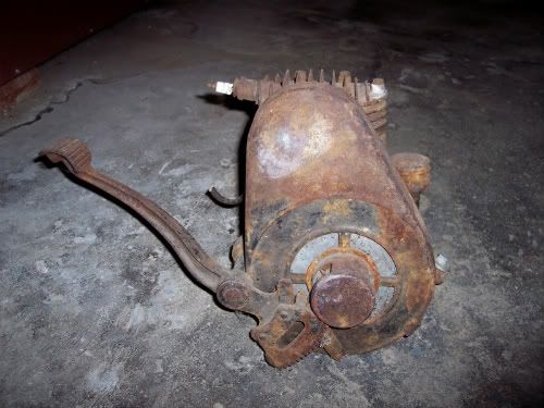
Briggs & Stratton 6S - A Beginnig

Home Model Engine Machinist Forum

Help Support Home Model Engine Machinist Forum:

This site may earn a commission from merchant affiliate links, including eBay, Amazon, and others.
Back to the model today with some work on the top side of the cylinder head. The top rounded profile was also machined on the rotary table. There's still some clean up to do around the bolt hole bolsters and then the entire underside to machine as well but that will have to wait for another day.


IMG_0078.JPG


IMG_0080.JPG


IMG_0081.JPG


IMG_0083.JPG
 
looking goood!
I personally love all these builds done on the smaller sherline/taig equipment.
this briggs is going to look top notch when completed.
 
years ago i thought about building a model of the briggs my dad had on his tiller but he wouldn't let me take it apart to measure all the parts.
now years later i see this build and it got me thinking about building one my self..................so i phoned dad about the tiller engine and he said he through it out 2 or 3 years ago :rant:

oh well i guess for now i will have to just follow this build and watch it unfold Thm:

keep up the good GREAT work th_wav

chuck
 
looking fantastic
can not wait till first pop
cheers pete.
 
Speedy...I can't say everything has been done on the benchtop equipment but probably 90% so far. The other 10% could have been done on the Sherlines but would have been more tedious in some cases. The only thing that required a more sizeable mill was the gas tank where some larger end mills were used.

Chuck...maybe you can find a non running engine at a local small engine repair shop...or if you aren't in too big a hurry, I will have a set of plans finished by the end of the build. I expect I have considerably more time in drawing and measuring that in actually making chips. Thanks for the vote of confidence though!!

Pete... the further i get into it them more impatient I become for that first pop too. Lets just hope its a pop rather than a fizzle!!
 
Progress this week has been a little slow but still some progress was made. The joining ring for the upper and lower halves of the gas tank was made and today I got the tank soldered together and cleaned up from that process. While checking it for any leaks I measured the capacity which was 3 oz. Now that its finished, it will be put away for a while.


IMG_0001.JPG
 
After the tank was finished (which took quite a while) I went back to the cylinder head. The rotary table was used to mill the recesses in the underside of the head. Then on the top side, the perimeter of each bolster for the bolt heads was milled down to the depth of the fins. For each of these the rotary table had to be centered, the the particular hole location centered on the RT, and then the milling work. With 9 hole locations and using a 1/16" end mill this took a while. Tomorrow I will finish cleaning up the fins with a 3/32" end mill now that there is a little more clearance around each bolt location. Two of the fins also need to be lowered in height to match the prototype. A little more radius work on the back side and connecting the valve recesses with the piston recess (on an angle again per the prototype) and the majority of the head will be completed. This has turned out to be a fairly intricate part with lots of different set-ups. I keep thinking how much easier some of these parts would be if starting out with a casting instead of bar stock. Maybe that will be a project for another time. All in all i am pleased with it so far and just hope I don't kill it in the final few operations. A few pictures follow.


IMG_0002.JPG


IMG_0003.JPG


IMG_0005.JPG


IMG_0006.JPG
 
Being an Antique Briggs engine collector I can recognize every piece as being
authentic.

Keep them coming Bill! :bow:

May I offer another challenge?
I have this Briggs Model Y with a Serial number of 117494.
That would indicate a manufacture date of February 1935.

1935BriggsY.jpg


In a perfectly restored condition, at auction, it would bring about half the cost
of a new 9 X 20 lathe. In it's current condition, if it were to be modeled, I would
consider a lower price. Like maybe shipping costs. ;) (It IS heavy!)

Just something to consider.

Rick
 
Wow, Bill. You've made quite a bit of progress since my last check on your build. I missed one of the cylinder head posts, but am back up to speed!
The head is coming along very nice. The fuel tank is simply beautiful. Would be a shame to paint it!

Dean
 
Rick....as if the 6S isn't challenge enough!! :big: If I am successful with the 6S then the "Y" would be a nice project for sure. Wouldn't it be even harder to find any missing parts though? Not to mention finding and restoring a "big brother" to run alonside the 1/2 scale "Y" as I now hope to do with the 6S. ;D Is yours in decent enough shape to be able to dismantle for scaling purposes. Though the 6S project has a ways to go, if it gets to the point of your needing to make that "Y" disappear then give me a shout.

Dean...I have had the same thought...I am not sure I could bring myself to paint the model once finished. In my head I still see it as a polished brass, aluminum, steel, stainless, etc. which I think would be perfectly ok. What I have considered is maybe painting just the flywheel cover a nice shiny black and leave the rest in its present state. I will have a better idea once enough pieces are made to start doing some sub-assemblies.

Thanks to you both for following along and offering your support!
 
Hi Bill
I've been in the background for a while, but still keeping an eye on things
from the start. what can i say fella, you are doing a fantastic job, and
such a brilliant write up, really enjoying following this post, gotta take my
hat of to you buddy.

Ken

 
Thanks Ken, its nice to know others have an interest in the project. Hope to have a little more to post later today.

Bill
 
It doesn't look like an afternoons work but most of the refinements to the head were done. Still left is lowering the height of two of the fins, blending the two different depths of the valve recesses and piston recess. rounding the edges of the fins, and doing something to eliminate some of the machine marks. Hopfully these will be finished shortly. This part has worn me down and I am ready to move on to something else for a while. I did order the 6-32 hex head bolts today that will eventually connect the head to the crankcase.


IMG_0007.JPG


IMG_0008.JPG


IMG_0009.JPG


IMG_0010.JPG
 
b.lindsey said:
This part has worn me down and I am ready to move on to something else for a while.

I'll bet. There's a lot of work in it.
You need some lathe work for a change of pace, Bill.

Works for me!

Dean
 
My sentiments exactly Dean !! Lathe?? Whats a lathe? Actually I have a few lathe items to do next...finish the cylinder liner bore and hone it, make the piston rings, thanks to some helpful advice from Doug Kelly (designer of the Snow Tandem model), and the little muffler which should be straightforward. After that then the connecting rod so the mill wont feel too deserted.
 
Moving right along Bill,

Keep at it, I always look forward to your updates... :) :) :)

Jeff
 
Thanks Jeff. I'm not happy with this part yet but its mainly cosmetic at this point so it will get there. I think it will look better with the spark plug and bolt heads in place even if only for a photo op...lol.

Bill
 
Bill, I think the lathe gets a guy back to "normal". Kind of does for me, at least.
I look at the lathe as my best gal. The mill is more like my sister. I love it, but we fuss at each other sometimes. Kind of demanding now and then, and quite opinionated.

That's my anthropomorphizing for the day.

Dean

 
Well said Dean...I knew when I saw your pic in the Men and their Machines thread there was an anthropomorphiz-er in there somewhere ;D. Actually My first thought was that it looked like a photo of an author you might find on the back flyleaf of a book cover. Very dignified and "Faulkner-esque" sitting out there on the veranda, even if you aren't a southerner :big:

Anyway, the mill and I had indeed had a fuss and a few choice words. After two days of rotary table/dial test indicator/mill work... the %^&*$ 3/32 end mill decided to dig in on the LAST radius cut. Fortunately it wasn't too bad and just a cosmetic defect but I was still ticked off!! And then somewhere in the grand scheme of creation there came into being JB Weld, which in my opinion is far and away better then duct tape for just about anything. But the downside was that i had to look at the defect for 24 hours while the stuff fully cured before making the cut again. Also fortunate is that it is on the intake valve side of the head cover, less heat than the exhaust side I hope, and on the underside where no one will ever see it. But I still know it is there :-[. If you look closely at the last photo above you can see the blemish in the lower left hand corner. So.....yes....I need some normalcy for a short spell anyway.

Which leads me to a question on materials.....

Was thinking of making the muffler out of stainless but then thought about it being screwed into an aluminum block (different rates of expansion, dis-similar metals in a hot and chemically charged area with exhaust gases, etc.) What do you IC guys think of that? Would another material choice be more appropriate? Or there is the possibility of using stainless for the muffler and aluminum for the 10-15 degree elbow that connects it to the block, but then there is still the muffler/elbow connection. Any thoughts or suggestions would be appreciated.


Bill
 
Its been a few days and the head is pretty much finished. Couldn't help but see how it lookes with the plug and bolts in place. Aside from that I got the cylinder liner bore finished and honed. After finding a suitable piece of stainless for the outer muffler casing work has begun on it as well as the inner core. Pictures of the muffler will be forthconing shortly. Below are a couple of the finished head and lined bore.


IMG_0011.JPG


IMG_0013.JPG


IMG_0014.JPG


IMG_0016.JPG
 

Latest posts

Back
Top