Is it just me? I am not getting a lot of your pictures?
You are using an out of date browser. It may not display this or other websites correctly.
You should upgrade or use an alternative browser.
You should upgrade or use an alternative browser.
Offenhauser Inline 4 cylinder, Might Midget Model Engine Build
- Thread starter Eccentric
- Start date

Help Support Home Model Engine Machinist Forum:
This site may earn a commission from merchant affiliate
links, including eBay, Amazon, and others.
A lot simpler than the solder method I have seen. The bushing is locked in place very nicely due to its ovality and of course the locktiteUsing a softer bronze is a good suggestion, I do have some softer Bronze that I have designated for use in making the valve guides. I had some bronze bushings laying around and thought I would give them a try. It requires some special attention when machining. Below are a couple of snaps of my second attempt.
View attachment 137577
View attachment 137578
I am please with the design changes to the connecting rod. The bronze bush is thicker and the cap looks substantial enough. I also was very careful when machining the bronze. I used lots of oil and stepped up one drill size at a time.
This conrod blank is ready for the outside "cosmetic" machining.
That material looks a lot like oil lite bush material ? which is a sintered material and difficult to get to very thin wall due to the particle size so bits fall offOffy – Conrods Part 1
I am going to try something different with the connecting rods. I want to install a bronze split bushing in the big end. It will be secured with Loctite and brass taper pins. As a warning, my first attempt was a failure as can see below:
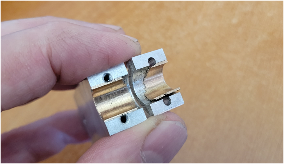
The bushing is too thin and the material is very brittle and hard to machine. I want the cap screw holes to clear the bushing, but the distances are really tight and the resulting bushing is too thin.
To back up a bit, the following images are of the desired connecting rod. It is not symmetrical as can seen in the side view due to the geometry of the crankshaft with respect to the pistons–the big end is offset from the piston center.
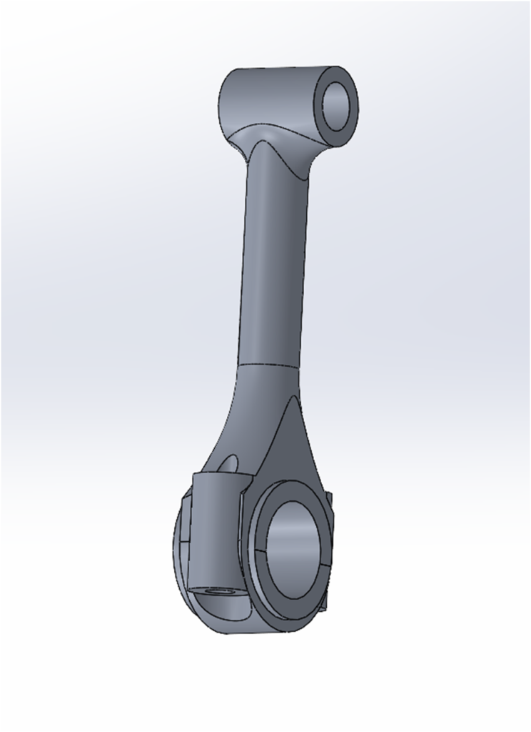
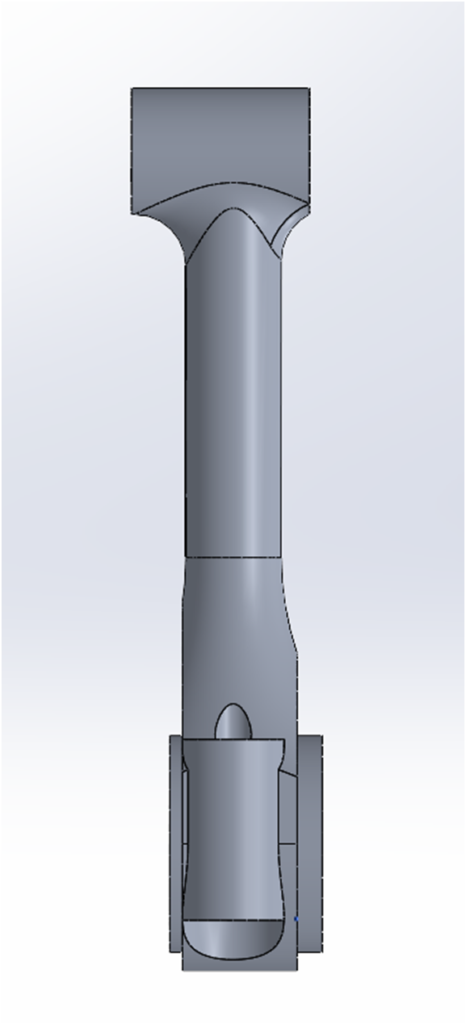
Below is the material squared up and ready to go, fortunately I only make one to start with.
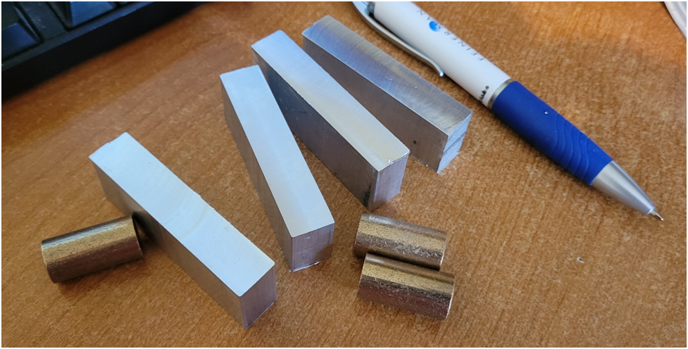
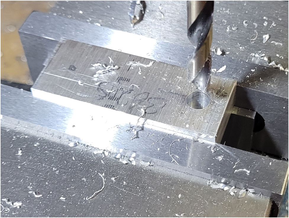
I drill a clearance hole in the work piece to facilitate CNC machining.
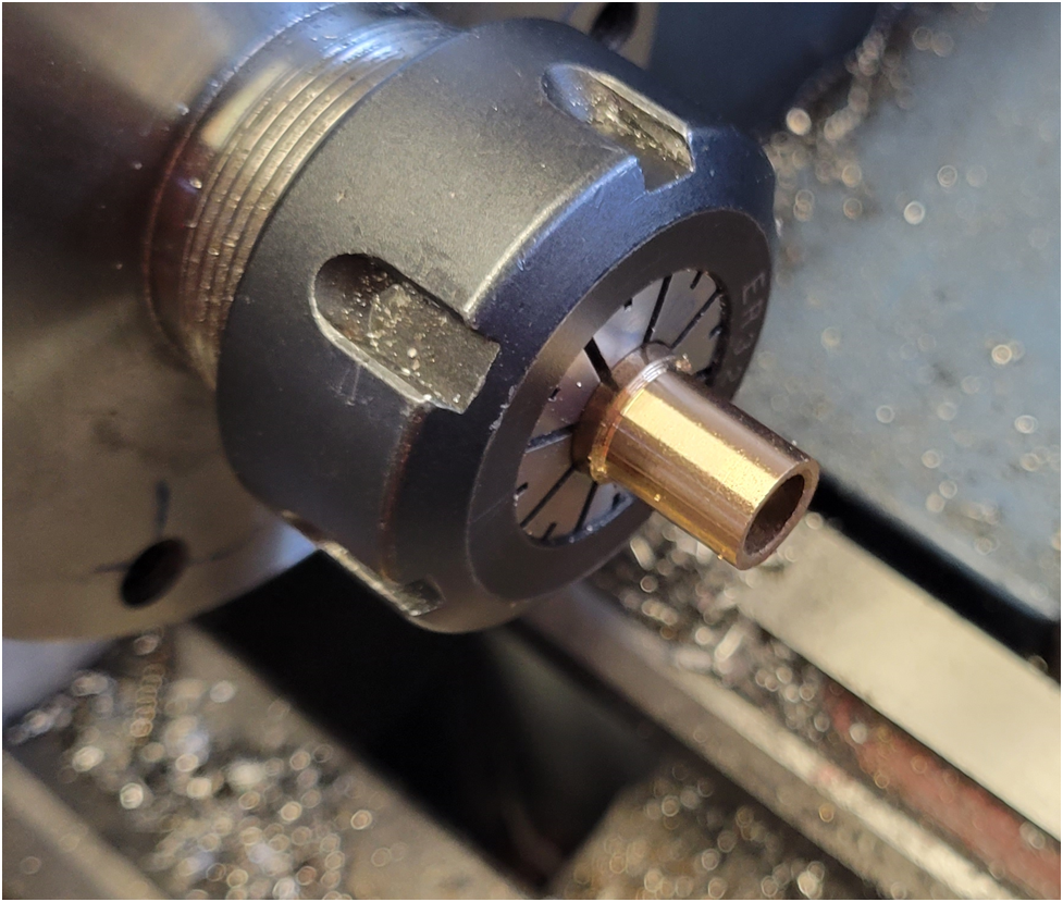
Then I turn the bronze bushing to size.
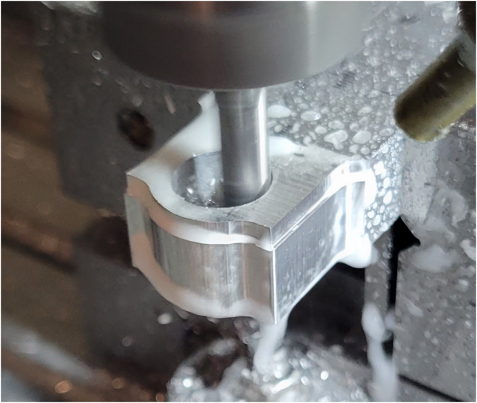
The big end profile is machined:
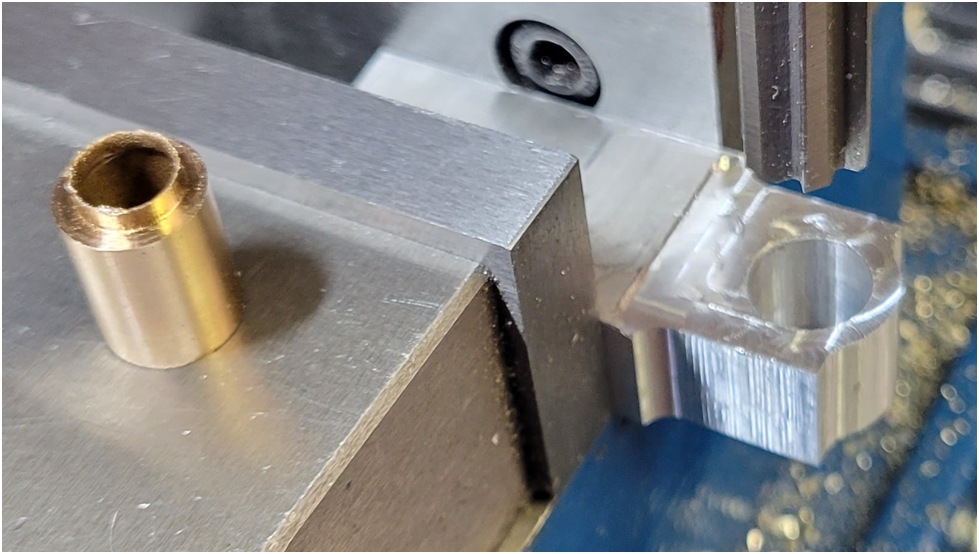
The hole is reamed and the bronze bushing is installed with Loctite.
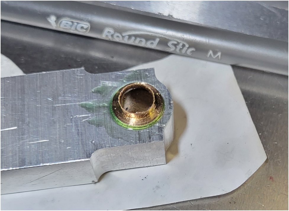
The end cap has the cap screws holes drilled/tapped and countersunk.
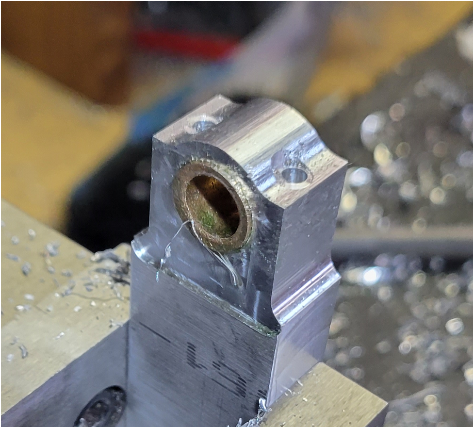
A slitting saw is used to separate the cap. I use a 1/32″ thick saw blade.
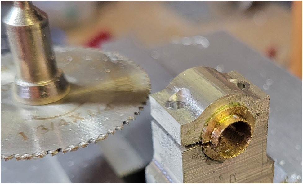
so far, so good.
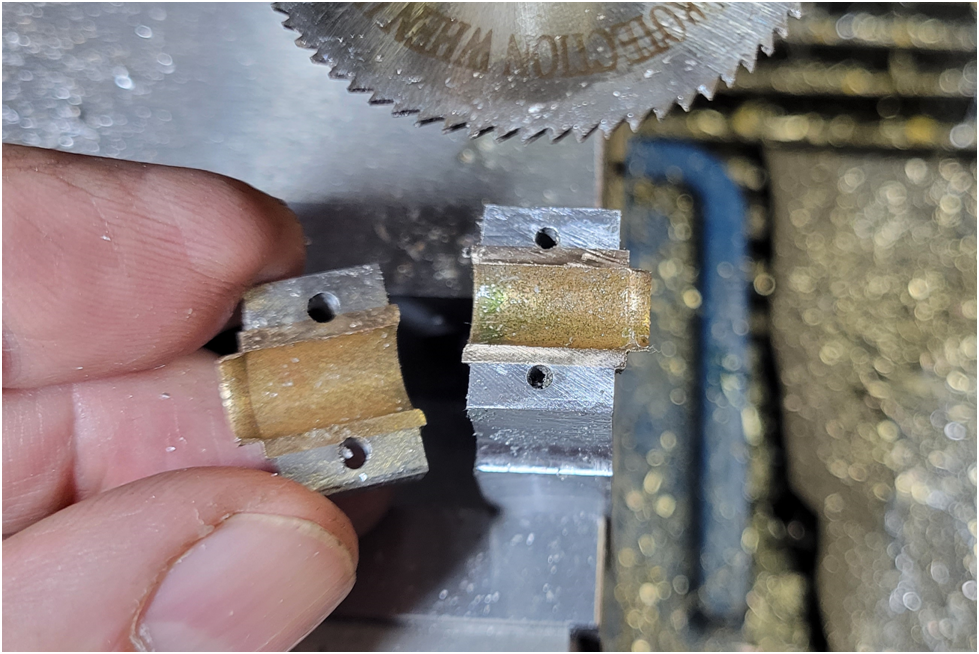
The surfaces are wet sanded and then the cap is screwed into place.
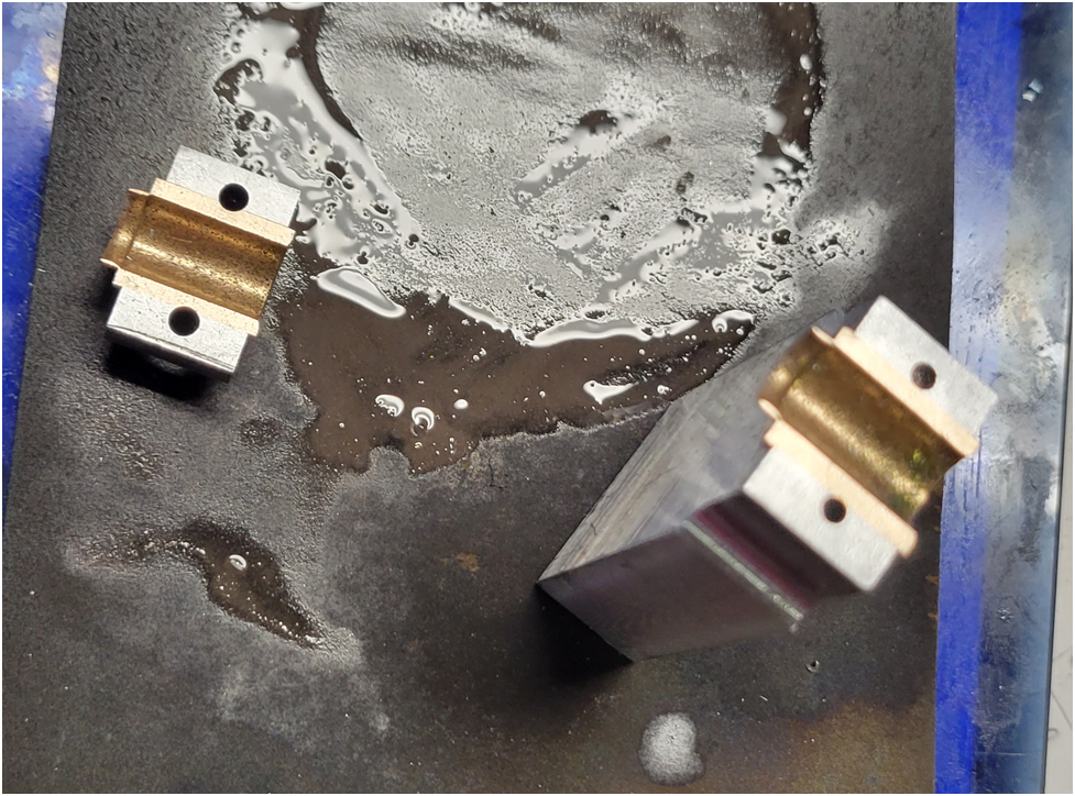
I then drill and ream out the big end hole. This is where things went awry. Perhaps the drill was not sharp enough, I got too aggressive, or the design was simply poor not allowing enough bearing material.
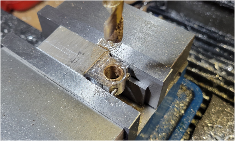
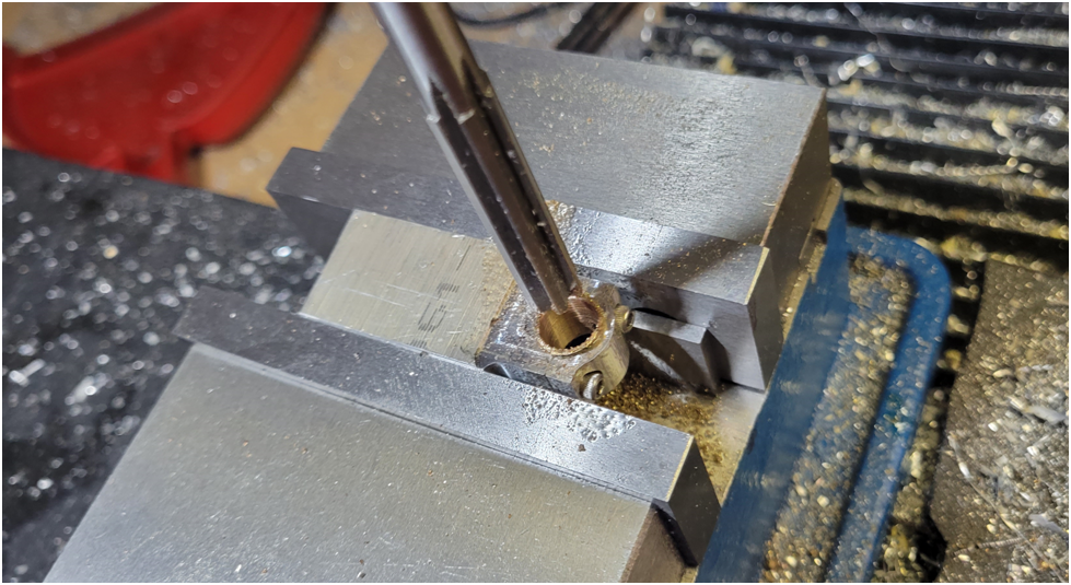
The gudgeon pin hole was drilled and reamed.
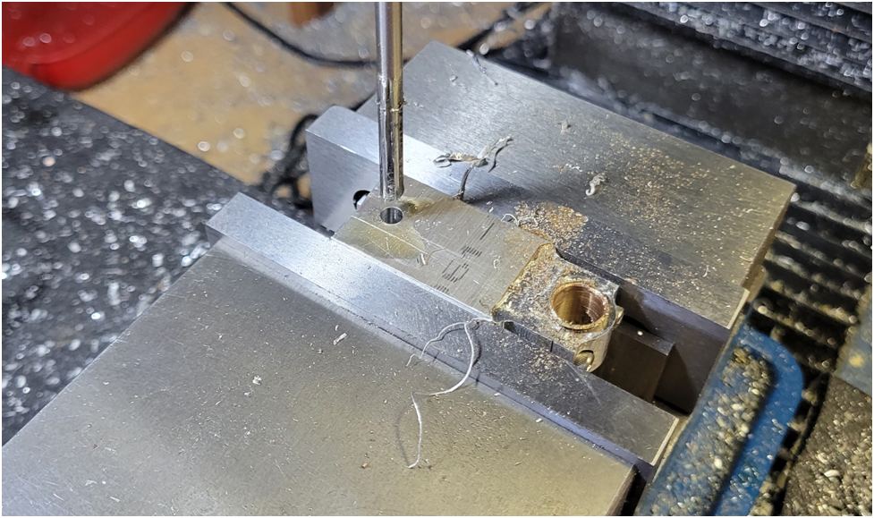
And again the end result:
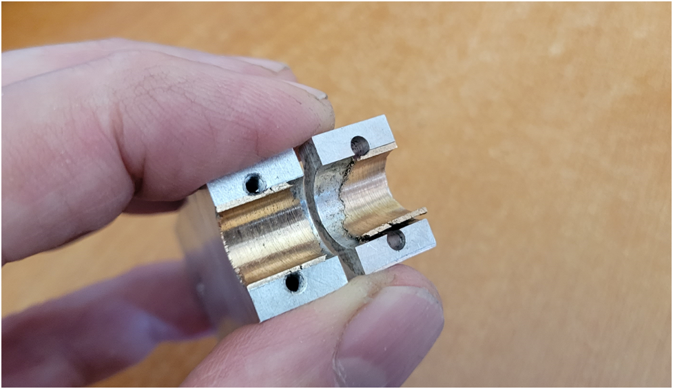
So I redesigned the Conrod. I moved the cap screws outward to allow for a thicker bearing and I added some material to the con rod cap.
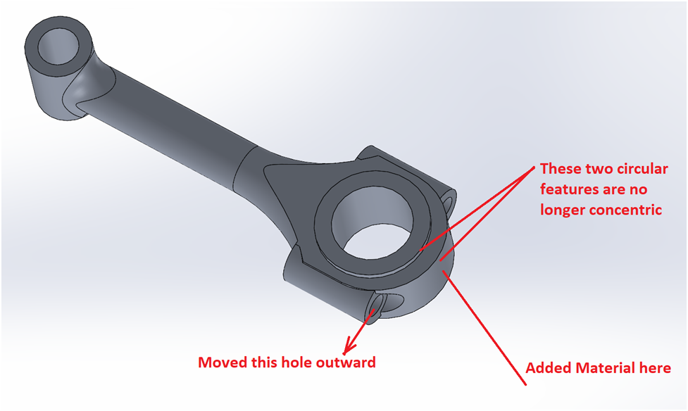
Below is the beginnings of a second try. Here I have completed all of the above steps to the point where I am letting the Locktite cure–that will be over night. The bronze bushing diameter the first time around was .4385″, the second attempt is .499″. The ID will be .375″, so I will have more meat in the bushing, but less in the cap.
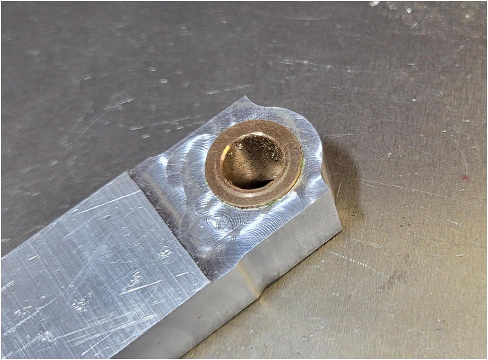
So, I am now waiting for the Loctite to cure. I will report back after the rest of the conrod machining is complete.
Paul
Eccentric
Well-Known Member
Offy – Conrods Part 3
I have spent the past weekend developing the tools paths to machine the outsides of the Connecting Rods. I will be using the fixture shown below to hold the conrods so the entire side can be machined in one go, then it is flipped over and the opposite side is machined in a like manner.
The fixture consists of two drill rod posts fitting in the big and little ends of the conrod and hold down screws clamping everything tight.
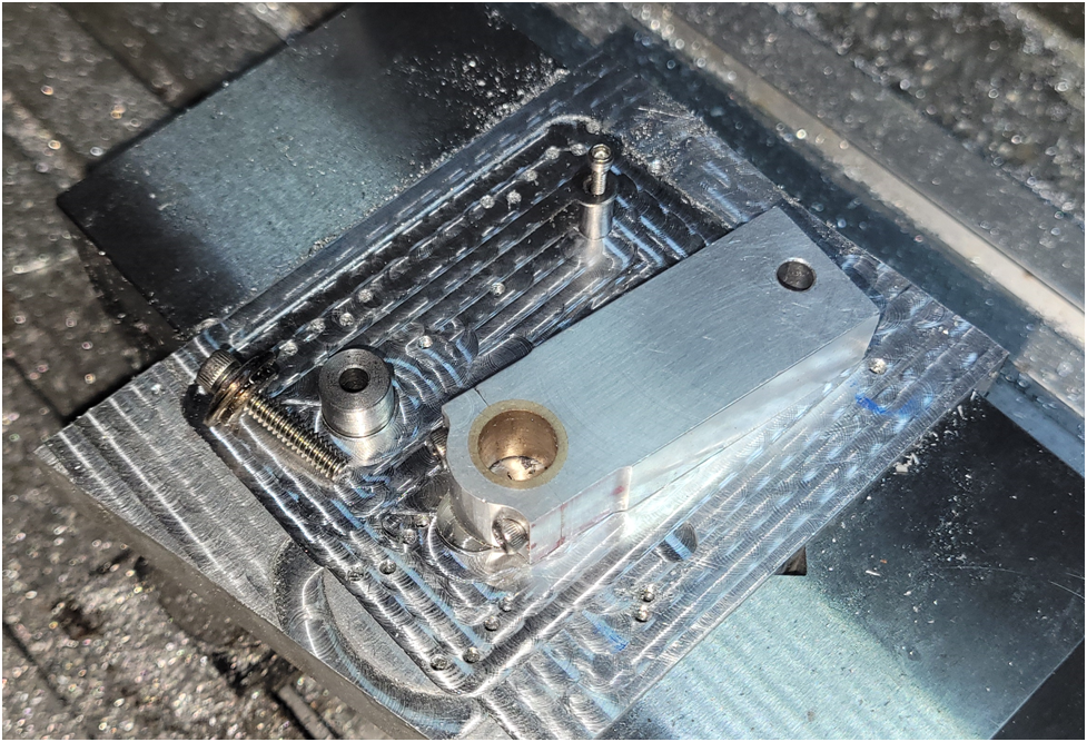
The first roughing operation is to machine the outline and remove most of the material.
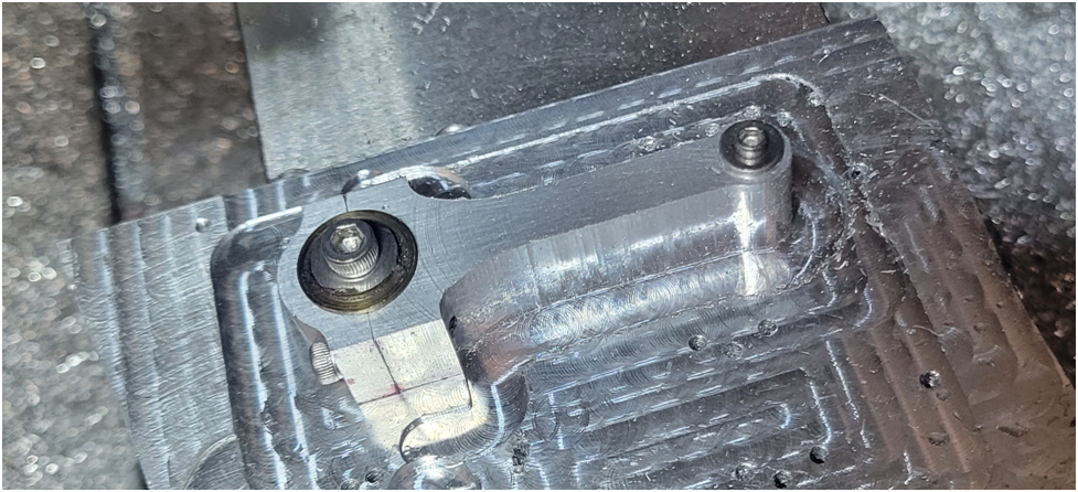
Then the top side is machined:
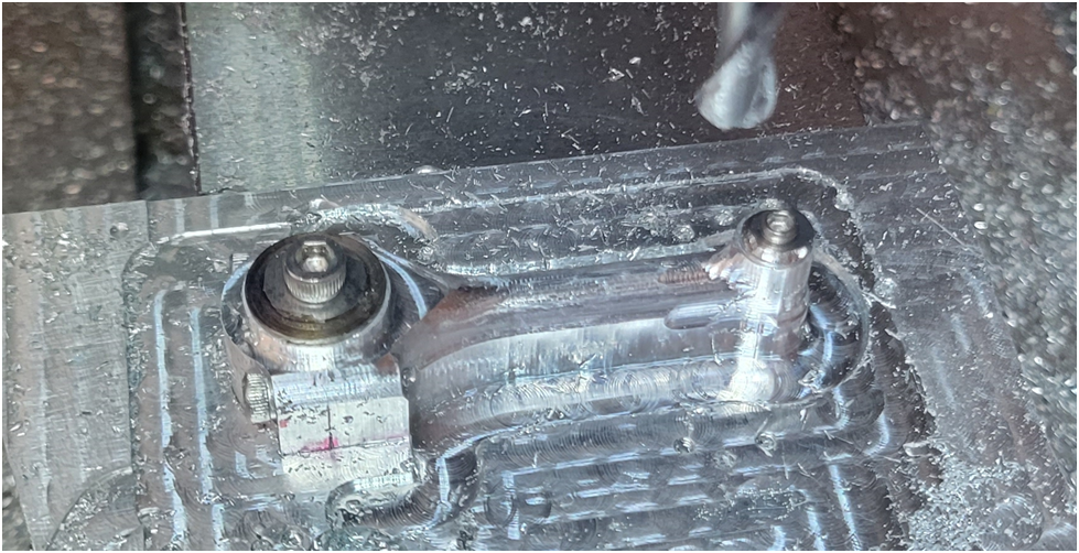
The part is flipped over:
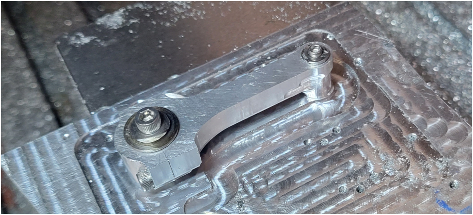
And the back side is machined:
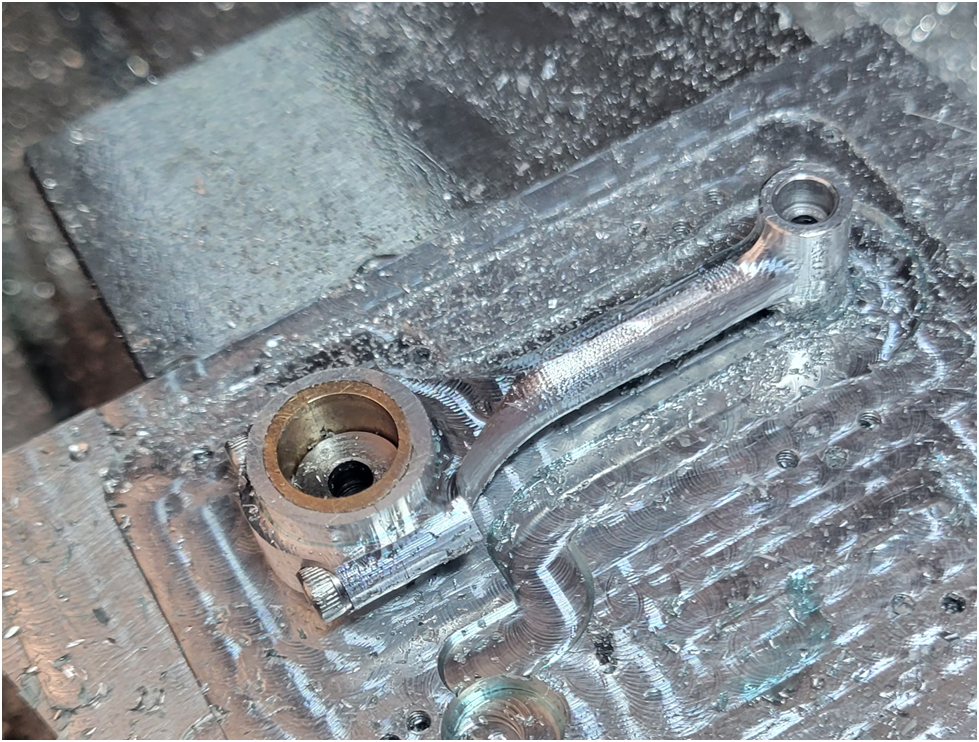
And below the conrod pulled off the CNC router. Now to machine the other three connecting rods.
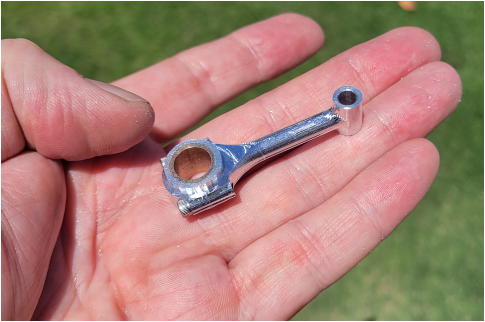
I am pleased how this technique of installing a bronze bushing worked out. Next time I won’t use an off the shelf oil-lite bushings, but some softer bronze stock.
I have spent the past weekend developing the tools paths to machine the outsides of the Connecting Rods. I will be using the fixture shown below to hold the conrods so the entire side can be machined in one go, then it is flipped over and the opposite side is machined in a like manner.
The fixture consists of two drill rod posts fitting in the big and little ends of the conrod and hold down screws clamping everything tight.

The first roughing operation is to machine the outline and remove most of the material.

Then the top side is machined:

The part is flipped over:

And the back side is machined:

And below the conrod pulled off the CNC router. Now to machine the other three connecting rods.

I am pleased how this technique of installing a bronze bushing worked out. Next time I won’t use an off the shelf oil-lite bushings, but some softer bronze stock.
Eccentric
Well-Known Member
Offy – Vavle Guide
Today I started fabricating the Offy’s Valve guides. Below is the result of the first one: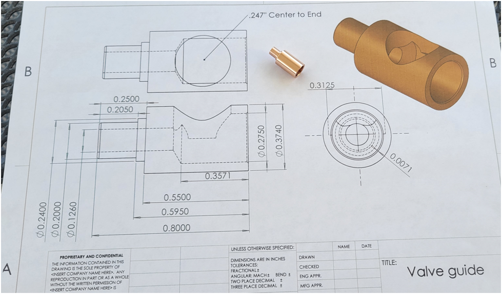
I don’t have any aluminum bronze (954) on hand, but I have a stick of phosphor bronze so I will use that for my valve guides. I started with the 1/2″ diameter bronze stock chucked up in lathe, faced it and spot drilled it for the large hole. Then before drilling the large hole I spot drilled for the smaller through hole, and drilled the small hole all the way through. The technique of using a large spot drill followed by a small spot drill is an interesting technique and is supposed to insure two holes of differing sizes are drilled concentric.
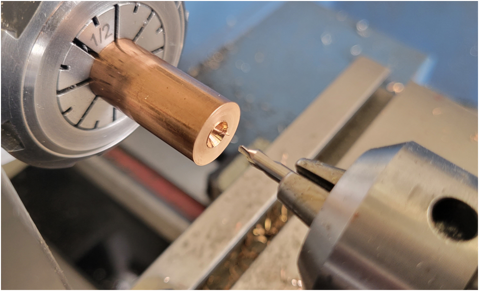
Then I drilled the larger hole to the proper depth, and turned the outside diameter to .374″. I coated the part in Dykem and cut the valve seat at 45 degrees. It is a really small seat, about .010″
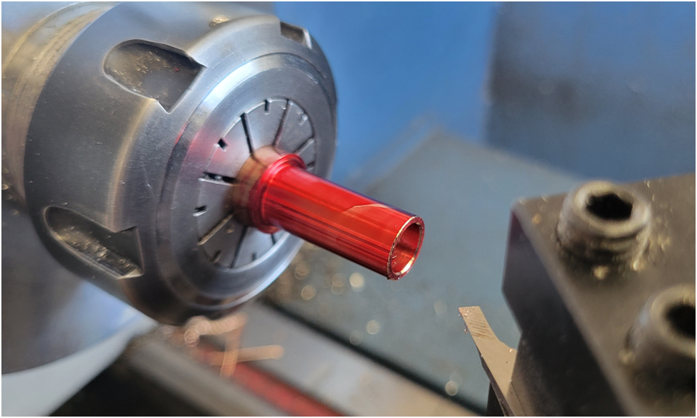
then I used a cut off tool to complete the outside machining.
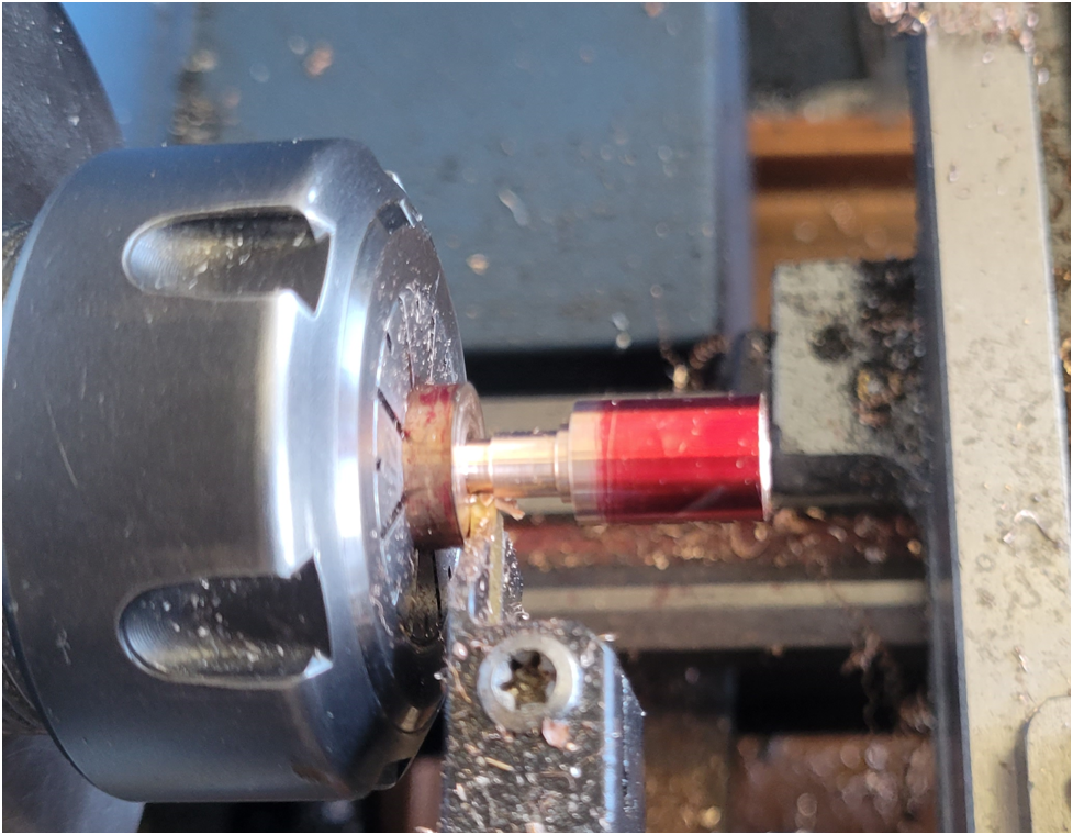
I have a DRO on my lathe and have come to really enjoy it. For a long time I did without, and even when I first got it on a whim I didn’t utilize it fully. It took me a while to trust it. But like I can’t imagine not having a DRO on my mill, I now can’t imagine not having the DRO on the lathe. When making multiples of a part, for example I need eight valve guides, the DRO makes the machining process so much smoother. I still use the micrometer for all final dimensions, but I can hit them with the DRO repeatably.
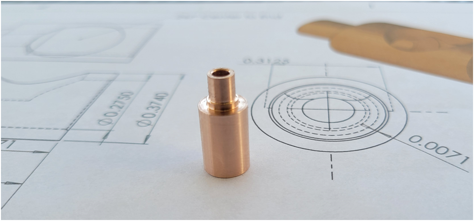
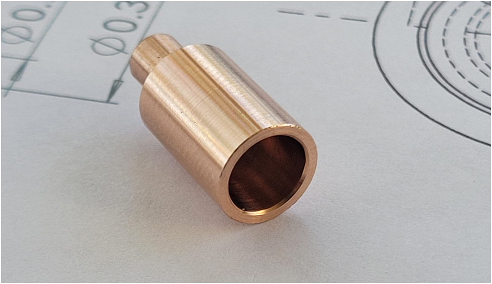
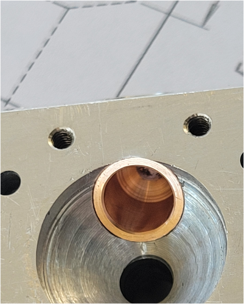
Below are a couple of images of the valve guide test fit in the head. I still need to machine the hole in the side of the valve guide, but I will do all of the valve guides at once in a single set up on the mill.
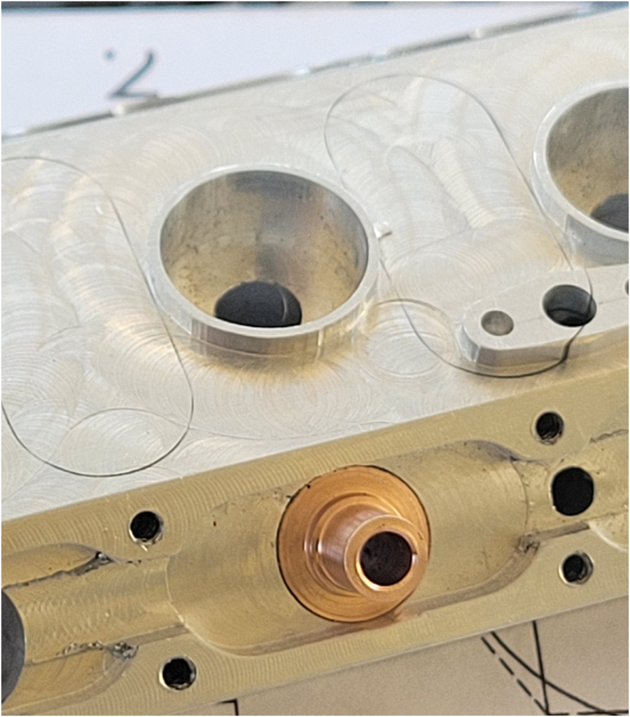
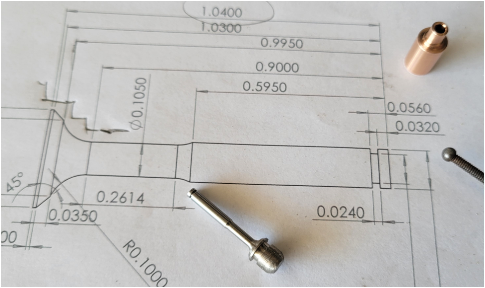
My original design called for a .093″ valve stem, but when I was drilling and reaming the small hole in the valve guide I began to second guess my ability to make a valve with such a small stem. I revisited the design and decided I have room for a valve with a 1/8″ stem. So I redesigned the valve guide and valve for the larger 1/8″ valve stem. the valve now looks like this:
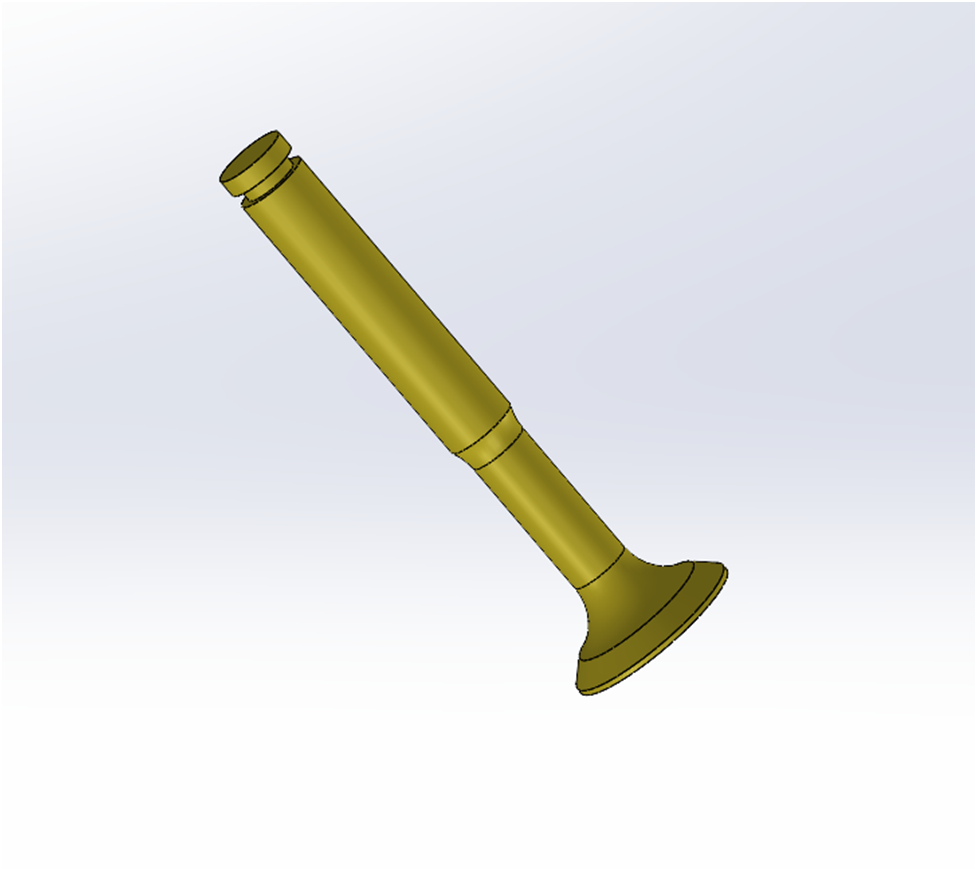
I have a fatter stem through the valve guide, but neck it down to maximize the flow into and out of the cylinder.
Fantastic work! I wonder how you are going to secure the valve guides in the head? I have used Locktite stud setting formula and still had some leaks.. The problem was solved with the wicking threadlocker Locktite This is a very useful product and its ability to creep into places is fantastic, sometimes too much so!

$599.00
$649.00
FoxAlien Masuter Pro CNC Router Machine, Upgraded 3-Axis Engraving All-Metal Milling Machine for Wood Acrylic MDF Nylon Carving Cutting
FoxAlien Official

$40.02
$49.99
Becker CAD 12 3D - professional CAD software for 2D + 3D design and modelling - for 3 PCs - 100% compatible with AutoCAD
momox Shop

$104.99
Sunnytech Hot Air Stirling Engine Motor Steam Heat Education Model Toy Kit M16-CF
stirlingtechonline

$99.99
AHS Outdoor Wood Boiler Yearly Maintenance Kit with Water Treatment - ProTech 300 & Test Kit
Alternative Heating & Supplies

$26.89
$34.99
Peachtree Woodworking Supply Bowl Sander Tool Kit w/Dual Bearing Head & Hardwood Handle, 42 Pieces Wood Sander Set, 2 Hook & Loop Sanding Disc Sandpaper Assortment, 1/4 Mandrel Bowl Sander
Peachtree Woodworking Supply Inc

$171.00
$190.00
Genmitsu CNC 3018-PRO Router Kit GRBL Control 3 Axis Plastic Acrylic PCB PVC Wood Carving Milling Engraving Machine, XYZ Working Area 300x180x45mm
SainSmart Official
![DreamPlan Home Design and Landscaping Software Free for Windows [PC Download]](https://m.media-amazon.com/images/I/51kvZH2dVLL._SL500_.jpg)
$0.00
DreamPlan Home Design and Landscaping Software Free for Windows [PC Download]
Amazon.com Services LLC
Just my 1.414 cents worth I use Loctite 680 for cages with no issues .
- Joined
- Jun 24, 2010
- Messages
- 2,468
- Reaction score
- 983
My bronze valve cage is similar to yours. I have to check my notes but I think I used 620, the high temp version, for bit of insurance. Judging by some torch testing I think (I hope) it will stay put.
One thing to mention is Loctite sets off crazy fast on bronze for some reason. Good thing I experimented on a tester because it may have caught me off guard.
My thought was that that an easy slip fit might help minimize potential distortion vs a close or interference fit so long as its within the prescribed annular gap. Time will tell if this was the right approach. I did the final seat cutting in-situ once glued in.
Attachments
Ron Colonna used Loctite (don't know which variety) but told me he had issues with his exhaust valves coming loose. When I did mine, I used Loctite 620 and for safety pinned them in place with steel pins. Steel wasn't necessary and will make them more dufficult to remove should the need ever arise. Care is needed to secure them at their edges without actually penetrating their interiors. - TerryFantastic work! I wonder how you are going to secure the valve guides in the head? I have used Locktite stud setting formula and still had some leaks.. The problem was solved with the wicking threadlocker Locktite This is a very useful product and its ability to creep into places is fantastic, sometimes too much so!
Eccentric
Well-Known Member
Yes, I will be using Loctite to retain the valve guides in the head. I had planned to use 638, but looking at the Loctite chart Peter attached 620 is intended for higher temperatures. They recommend an "Activator", which I have never used. It is a good tip to be careful of it setting too quickly, once Loctite sets it is difficult to remove without lots of heat.
I will also be following Terry's lead and installing small pins to secure the valve guides. The two pictures below show the predrilled holes for these 1/16" pins. The first shows the entry point of the pin, and the second shows the hole just breaking through where the valve guide will be installed. It intersects the valve guide high up where there is plenty of material to bite into.


The reason I have chosen to cut the seat in the valve cage before installation in the head is two fold. One, I have a lot of time invested in the head and would hate to mess up a valve seat and lose the head. Secondly, I make my valve cages and valves as matched pairs, testing them individually under vacuum before installing the valve cage in the head. I drill the valve guide holes and cut the valve seat in the same set up in the lathe and think I can maintain good concentricity this way.
Good discussion, thanks guys.
I will also be following Terry's lead and installing small pins to secure the valve guides. The two pictures below show the predrilled holes for these 1/16" pins. The first shows the entry point of the pin, and the second shows the hole just breaking through where the valve guide will be installed. It intersects the valve guide high up where there is plenty of material to bite into.


The reason I have chosen to cut the seat in the valve cage before installation in the head is two fold. One, I have a lot of time invested in the head and would hate to mess up a valve seat and lose the head. Secondly, I make my valve cages and valves as matched pairs, testing them individually under vacuum before installing the valve cage in the head. I drill the valve guide holes and cut the valve seat in the same set up in the lathe and think I can maintain good concentricity this way.
Good discussion, thanks guys.
Eccentric
Well-Known Member
Offy – Vavles
This is a quick update on my progress, I am working on fabricating the eight valves for the engine.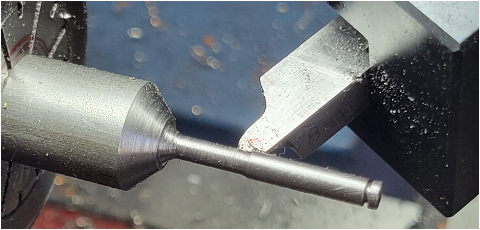
I cut the 45 degree seat and large radius with the lathe in reverse to facilitate access of the tool.
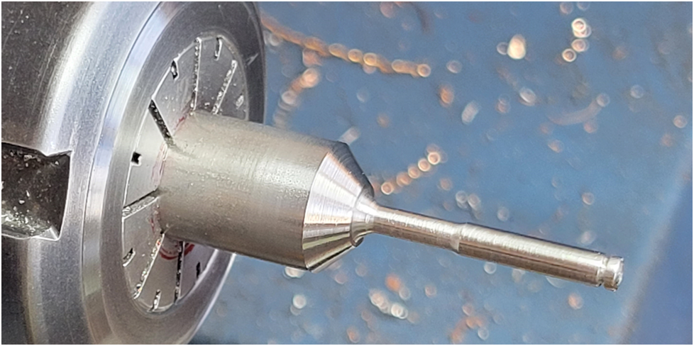
And below is the valve ready to be lapped into the valve cage. I leave the slug of material on the face of the valve for this purpose, this of course will be removed later.
Eccentric
Well-Known Member
Offy – Exhaust System
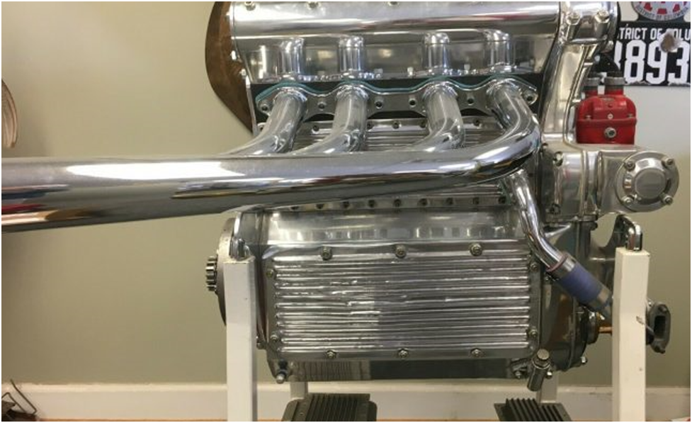
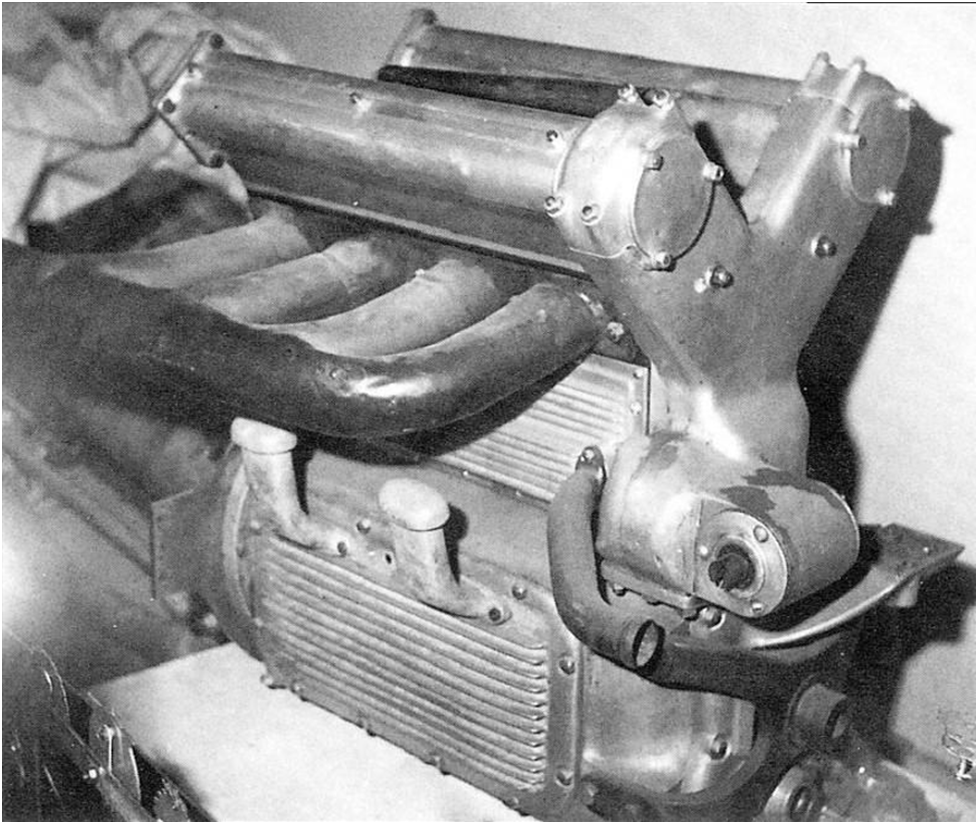
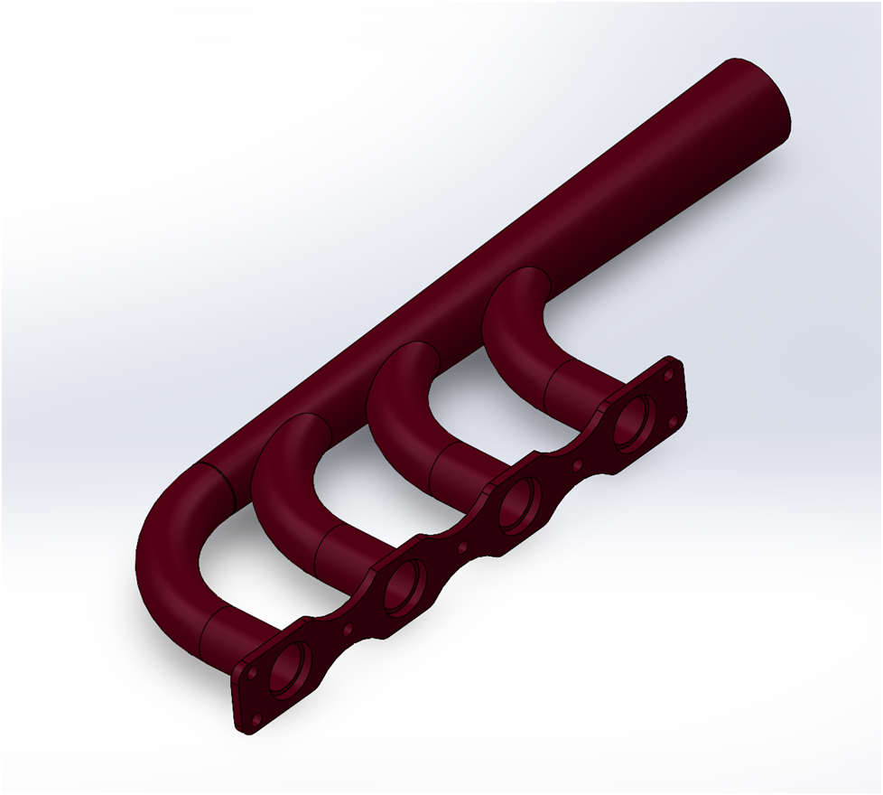
Below are a couple of photos of Offenhauser Exhaust systems. Mine will be fabricated from a brass flange plate, four 3/8″ 90 degree bent 304 stainless steel tubes and one conical collector made from a 16mm X .5mm 304 stialness steel tube.
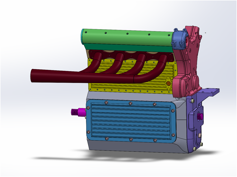
Below are a couple of views of the 3D model. Frankly I just adjusted the lengths and conical collector flare until I thought the exhaust system looked good. I reviewed Terry Mayhugh’s method for making his Offy exhaust system and will attempt to follow his lead.
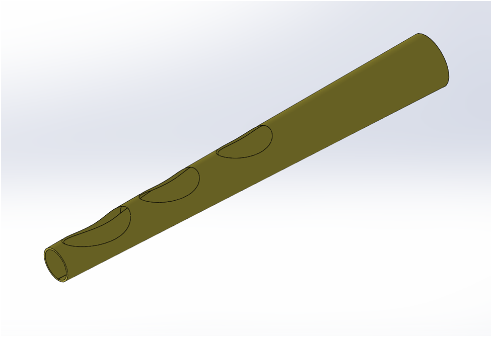
Below is the most complicated part, the conical collector. It is just under 5 inches long, 3/8″ at one end and 16mm (~5/8″) at the large end.
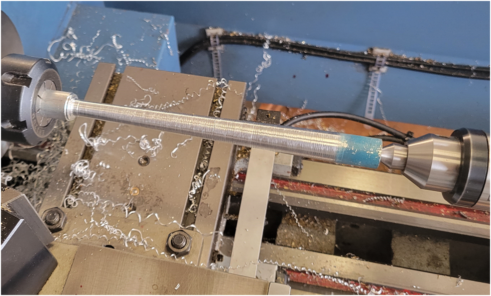
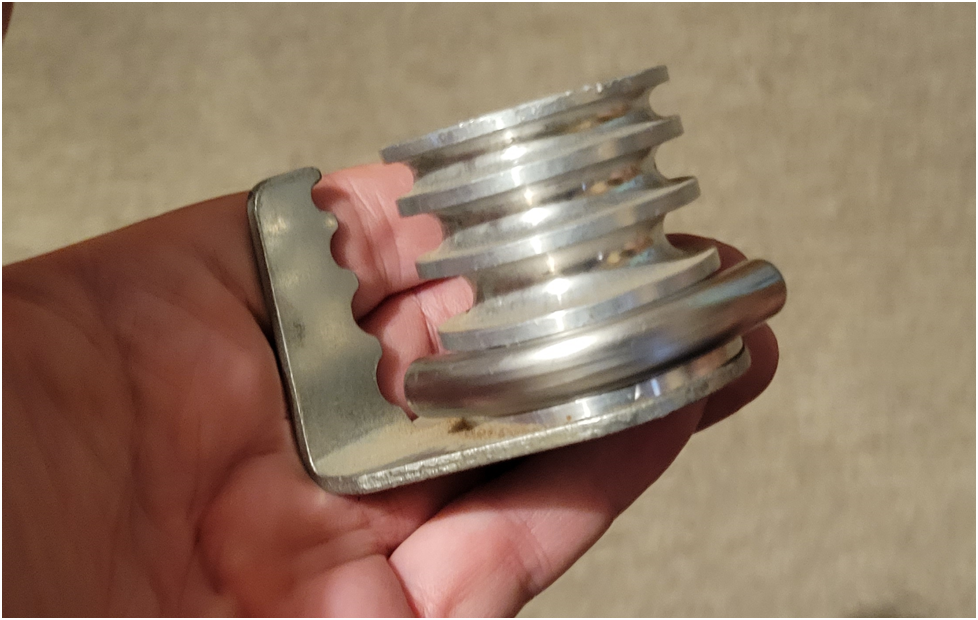
First I made a couple of fixtures. The internal mandrel started as a 5/8″ diameter length of aluminum stock, tapered to match the inside of the cone. There are two ways to machine this, the cleanest is to adjust the tail stock so it is offset to one side, the difference between the two radius of each end of the cone. Then turn on centers. I chose a second method because I did not want to have to re tram the tail stock when I was done. So I used the compound to cut a taper equal to the cone angle. I took cuts in 1/2″ increments down the length of the stock, resetting the compound as I went.
I 3D printed female molds of the cone as shown below using 9 layers around the perimeters and 60% infill. These forms are almost solid plastic.
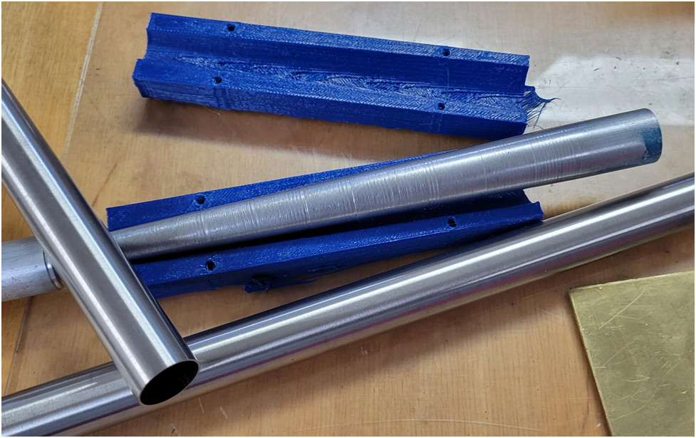
I cut a triangular notch out of a length of 16mm tube using a Dremel cut off wheel, then used the mandrel and forms to shape the cone closing up this gap. This was very tricky and the .5mm thick stainless steel was not easy to reshape. I then welded the slot closed, this was also a very tricky operation as the .5mm (~.020″) thick SS is very hard to weld without just melting it. I made a bit of a mess, but the part came out OK after grinding. I don’t know if I could do any better on a second try. I suppose I could go back and fill in some of the voids with the MIG welder, but it is so easy to just punch a hole in the tube. I will try to fill the last voids with silver solder later. I have not decided what finish I will use on the exhaust system, nickel plate or just a black high temp coating.
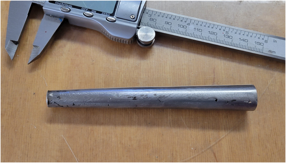
I then bent the four 3/8″ diameter SS tubes.
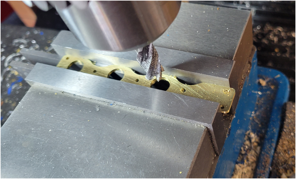
I machined the exhaust flange plate that will mate to the cylinder head out of brass sheet.
This is where I stand now. I have a little more thinking to do. I want to cut the three holes in the side of the collector tube to match the bent feeder tubes, but am having problems with my CAD program. I thought I could punch the holes as shown in one of the earlier CAD images of the collector tube, then unroll it, or flatten it, like a piece of sheet metal, but I am not having any luck. Then I could print this out on a piece of paper, over lay it on the collector tube, mark and cut the holes. This still seems the best plan, I just need to figure out how to make SolidWorks cooperate.
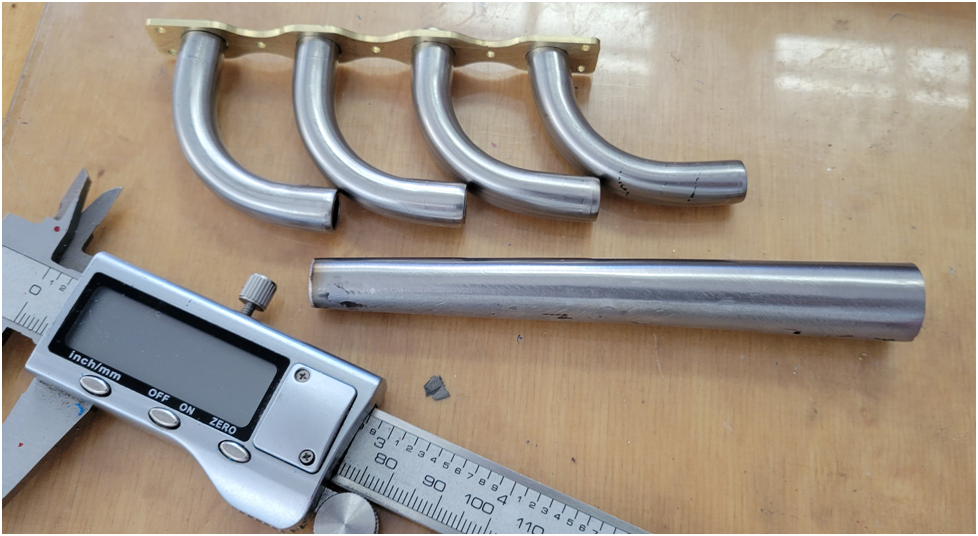
I will make a rigid fixture to hold all the parts in the correct orientation so I can easily silver solder it all together. I need to think about this a bit as well.
All for now, I think I have completed the difficult parts.
Excellent !, very enjoyable following your work. Thank you.
Eccentric
Well-Known Member
Offy – Exhaust System Part 2
I modeled the exhaust collector cone in CAD and then flattened it to give me a pattern of the holes as shown below: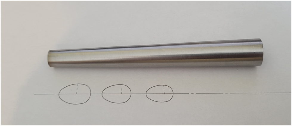
I glued this on and then machined and ground out the material.
Below is a test fit of one of the bent tubes:
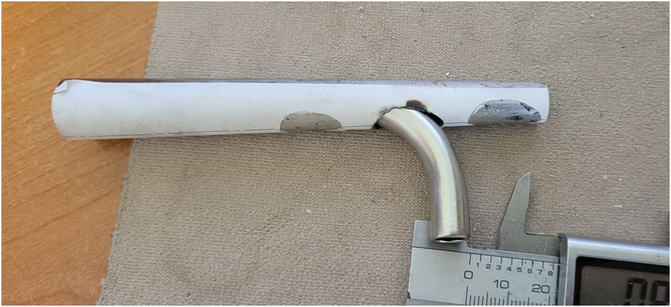
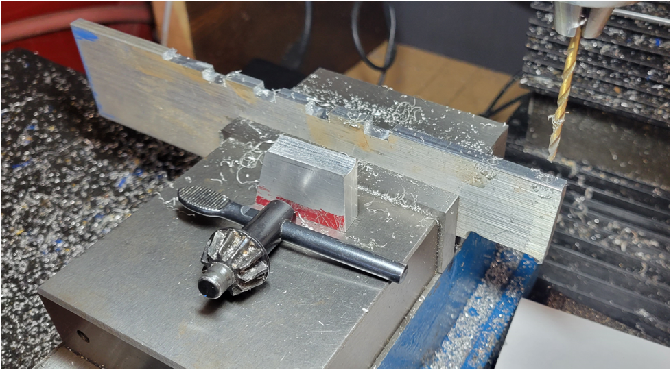
Next I grabbed a piece of scrap aluminum and made a fixture to hold the exhaust system in the proper position for silver soldering.
Below is the exhaust system ready to silver solder. Or so I thought.
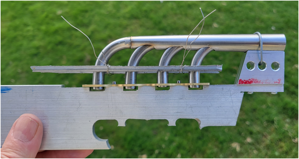
In hindsight there is a bunch of stuff wrong with my fixture. And I found out the hard way.
- The 1/4″ plate that I used to secure the exhaust flange acts as a heat sink and wicks all of the heat away from flange as it is silver soldered. An excessive amount of heat was required to get the silver solder to melt, and it ended up just globbing up at the joint. I had to come back later, reheat and shake off the excess.
- I used thin strips of aluminum held together with very thin stainless steel wire to align the feeder tubes. The thin aluminum strips ended up melting and dribbling all over the collector tube and the thin stainless steel wire simply vaporized. Primarily due to excessive heat, see 1. above.
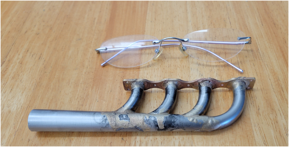
This is only the second time I have attempted silver soldering and I know that I need a better fixture and more practice.
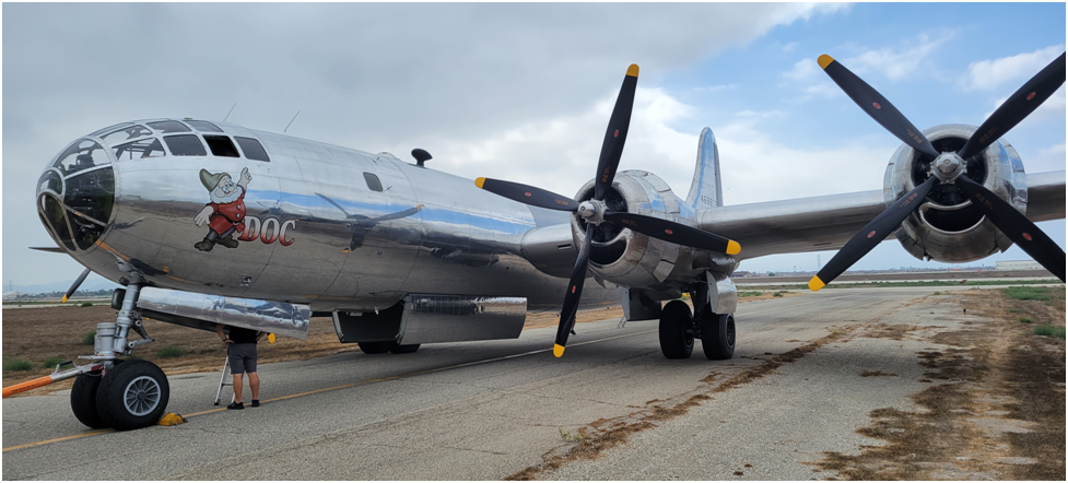
Doc, one of the remaining flying Boeing B-29s visited my air field this last week. This amazing World War II era bomber holds a special place in my heart as my father regaled me with many SuperFort stories when I was a kid. He was in the Air Force, and as a B-29 engine mechanic his time in the war was spent at forward Pacific island air bases keeping them flying.
A little bit of carefull handwork and I think that will still clean up nicely. Are you going to finish it with a high temp paint?
Just a thought, could you have chamfered the holes in the engine side of the flange and silver soldered from that side. I can appreciate the difficulty with such thin stainless. I tend to have good luck sometimes cutting and placing the solder, lots of different angles so I can appreciate the issues with trying that. I have some very small diameter regular solder that I coil around a joint maybe they offer a small diameter silver solder wire.
Hate it when the base metal is bright hot and the little bit of solder is sat there doing nothing
Of course lots of bright ideas after the fact, that’s easy!
Nice job though and again I bet it cleans up nicely.
Last edited:
Eccentric
Well-Known Member
Offy – Intake Manifold
I like the look of the original dual side draft carburetors as shown in the following photo:
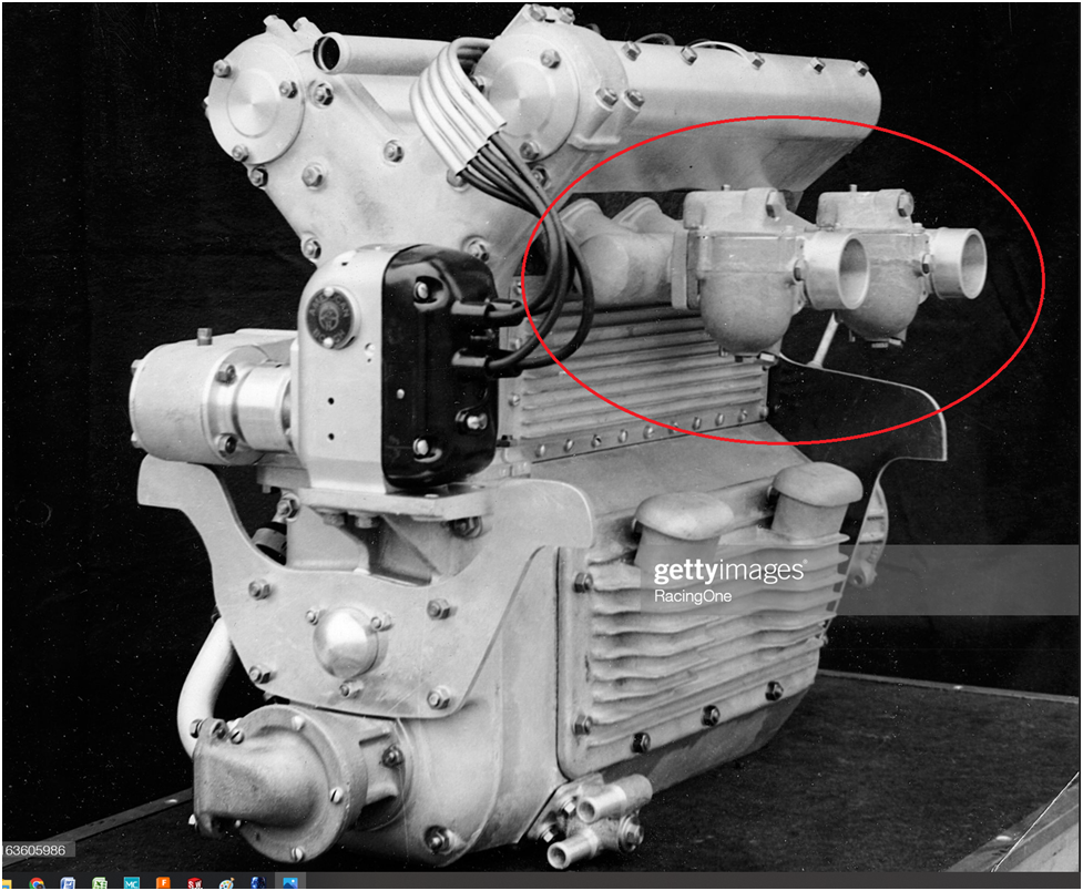
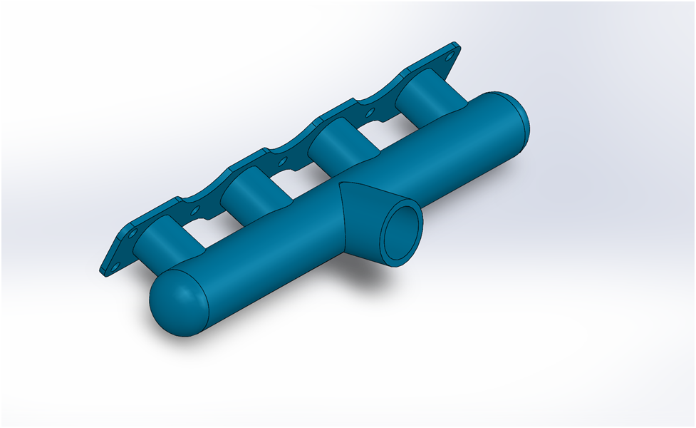
However, I have never made a carb before and want to start with a single carb set up for initial engine checkout.
That is what I am going to fabricate here and this is the design I have settled upon:
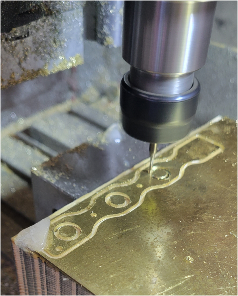
Below is the flange that mounts to the cylinder head being made on the CNC router. In the lower left hand corner is an ice chip that I used to keep the part cool during machining. My mister broke and I didn’t want to wait until another was delivered. When machining parts that use 5-minute epoxy as the hold down strategy, the parts needs to be kept cool, or the epoxy will soften or even give way and you end up with a ruined part at the least.
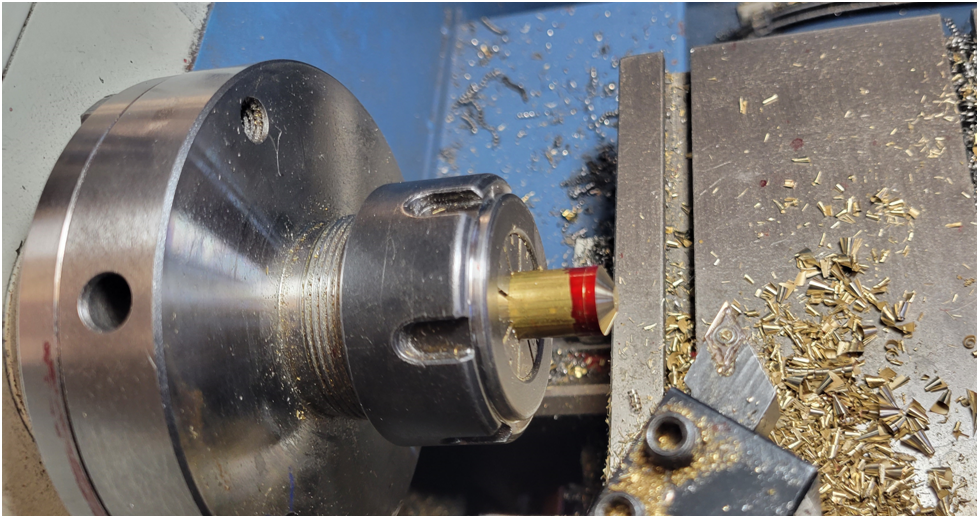
The end caps were machined from the solid. I took a 30 degree cut removing most of the material, then rounded the part with a file on the lathe.
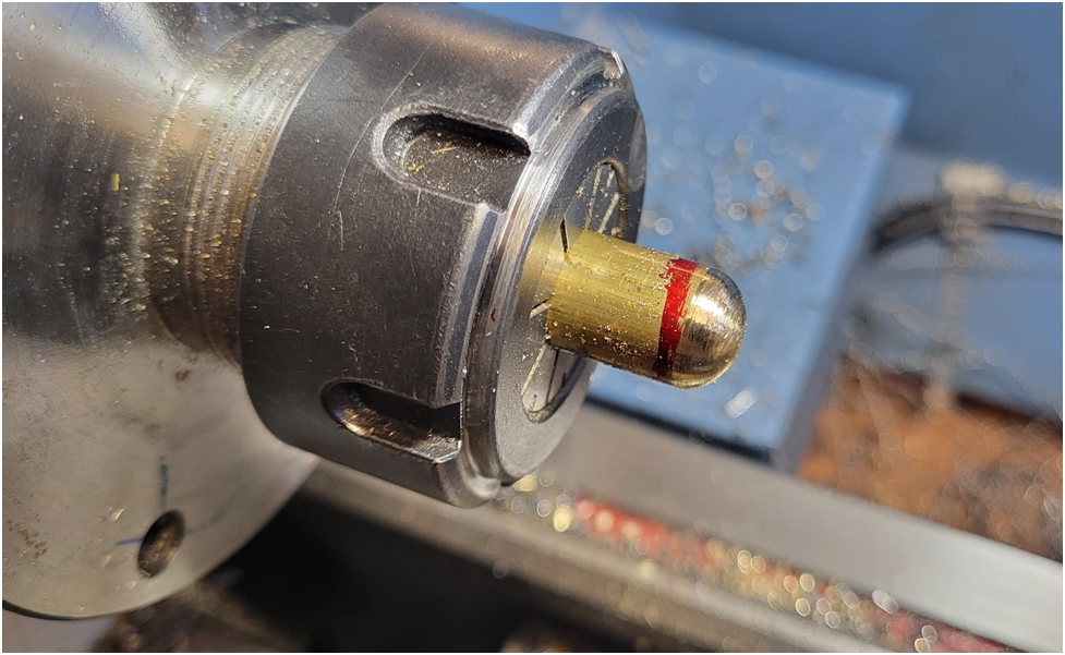
A step was then machined before parting off so the cap fits snuggly in the larger intake tube.
The large cross tube is .5″ in diameter, so I used a .5″ end mill to shape the intake runners and the carburetor mounting tube.
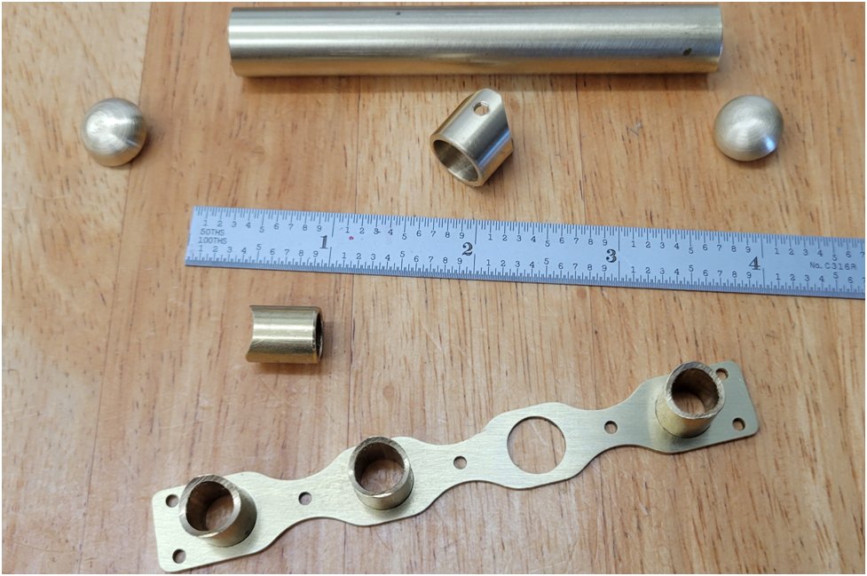
Below the parts are test fit. I decided to solder the assembly together first, then machine out the holes in the large cross tube. I think this will simplify the alignment of the parts during soldering.
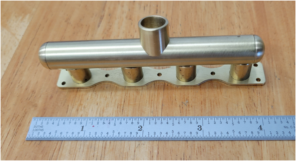
I am still formulating my soldering strategy. My thought is to solder the feeder tubes to the flange first, then the cross tube to the feeder tube and the carburetor tube last. Jewelers often use different formulations of silver solder that have slightly different melting temperatures that allow them to stage assembly of a piece. They use the higher temp solder first, the idea being they do not need to raise the temp of the piece as high for subsequent solder operations and not disturb previous work. The single roll of silver solder I have nearly broke the bank, so I am not going to be purchasing additional types.
Don't forget that jewelers don't typically buy a pound of solder; they buy ounces or fractions of ounces. Especially small shops and hobbyists.
These guys are one of the big name suppliers in the US.
https://www.riogrande.com/product/silver-sheet-solder-assortment/101199GP/?code=101199
1/4oz each of four different grades of solder. I'm sure you could look around and find other options.
These guys are one of the big name suppliers in the US.
https://www.riogrande.com/product/silver-sheet-solder-assortment/101199GP/?code=101199
1/4oz each of four different grades of solder. I'm sure you could look around and find other options.
peterl95124
Well-Known Member
- Joined
- Feb 22, 2020
- Messages
- 526
- Reaction score
- 345

I am still formulating my soldering strategy. My thought is to solder the feeder tubes to the flange first, then the cross tube to the feeder tube and the carburetor tube last. Jewelers often use different formulations of silver solder that have slightly different melting temperatures that allow them to stage assembly of a piece. They use the higher temp solder first, the idea being they do not need to raise the temp of the piece as high for subsequent solder operations and not disturb previous work. The single roll of silver solder I have nearly broke the bank, so I am not going to be purchasing additional types.
I really like the look of your exhaust manifold, it should clean up nicely, and for the intake my advise is to braze the stubs to the main tube first (using the flange plate to hold them in alignment) then turn it over and gravity will hold them together when you're brazing to the flange plate. I've tried the method of different melting point solders but have found it unnecessary, a previously brazed joint is very hard to melt all the way around so even if it partially re-melts the piece won't move, and they seem to be highly resistant to re-melting anyway. I use 56% for close fitting parts and 45% for gap filling, and don't hesitate to do multi step brazing regardless of the silver formulation MP.
back to fixturing, I brazed the flanges only my exhaust tubes by screwing the flanges down to a steel bar with mica insulation in between. the mica didn't really insulate thermally as I had hoped, the steel bar got almost red hot, but it did prevent the flanges from accidentally getting brazed to the steel bar. I think "machinable alumina" would work as an insulator, but these days its another "break the bank" item, so sadly I haven't bought any since Small Parts Inc went out of business.
I think an Offenhauser derivative (maybe "standoff scale") will be in my future. So many thanks for sharing.
Similar threads
- Replies
- 11
- Views
- 1K
- Replies
- 117
- Views
- 43K
- Replies
- 14
- Views
- 9K


![Learning AutoCAD Civil 3D 2014 [Online Code]](https://m.media-amazon.com/images/I/51F3yi9fokL._SL500_.jpg)


