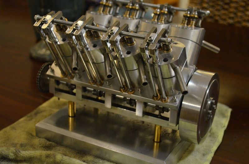
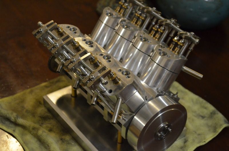
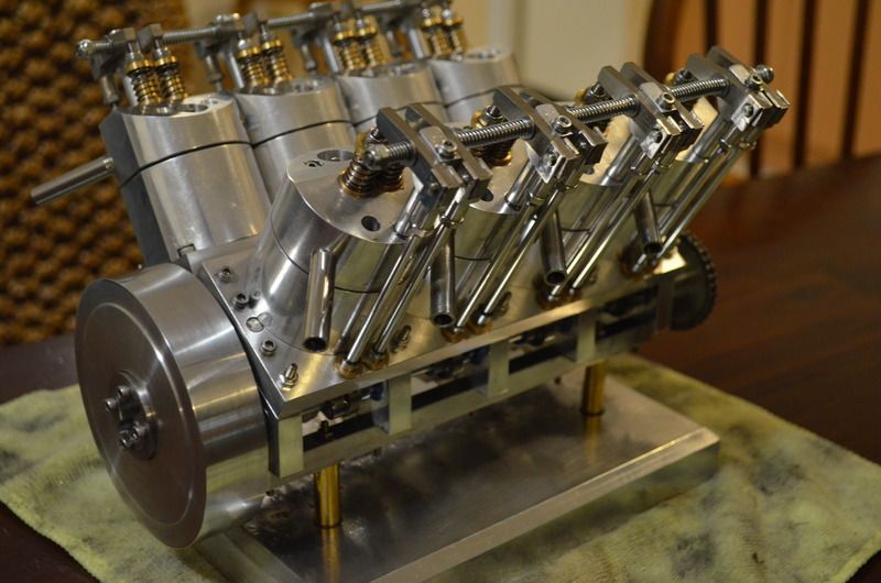
V8 nitro engine

Home Model Engine Machinist Forum

Help Support Home Model Engine Machinist Forum:

This site may earn a commission from merchant affiliate links, including eBay, Amazon, and others.
Well the firing order side of things has turned out to be a lot more complicated than I first thought. And at this stage I really have no idea. I was wrong about machining the flats at 90 degrees on the cam shaft to mount the cams. They should (I think) be set at 45 degree intervals. But again, this will change the firing order depending on how I put the flats onto the shaft. If I do it this way, it will simply fire in order eg 1 2 3 4 5 6 7 8.
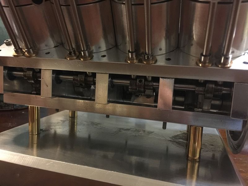

If anyone can provide assistance on this, I'd really appreciate it. I'm pulling my hair out with this one.
I hope my problem actually makes sense to start with...

Id be happy to offer any assistance I can
 
Thank you all for your input. I appreciate it. At this stage the camshafts aren't fixed to the shaft, so I'm able to modify them in any which way to manipulate the firing order.

I had a search through my rough sketches that I did and found that the v bank is 112.9 degrees. I really should have made it 90 to make things a lot simpler, but this factor mearly skipped my mind.

Pickleford, if there's anything you could add that would help, I'd appreciate it.

Cheers again all

Andy
 
I went back through all the posts and in post #14 there is a picture of the crankshaft. I know that pictures can sometimes be deceiving but the cranks throws don't look to be at 90 or 180 to each other. If I'm wrong I stand corrected but the angle of the throw in second cavity looks a little bit different than the last cavity. I also did a layout with a 112.90 cylinder centerline spacing and it looks really flat. Your pictures don't seem to show that wide of a separation angle. I'm only bringing these points up so that I can help you solve your cam timing issues. I'm not doing it to question what you have done. Let's say your crank is in fact a 90 degree crank and your cylinder spacing is 112.90 degrees. It won't be a problem to time the cams for each cylinder but it's sure going to have and odd firing order.
Let's make the first cylinder on the right bank looking from the top as #1 and the other 3 cylinders on that bank as 2, 3, and 4. Now that makes the first cylinder on the left bank as #5 and the rest on that bank as 6, 7, and 8.
Cylinder #1 fires. Now the crank turns 112.90 degrees and #5 fires, but being as the crank has 90 throws one of the other cylinders is going to fire when the crank has only turned 90 degrees so you will have that 90 firing space then a 22.90 degree firing space.
The engine will still run but it will have an odd staccato with the cylinder bank angle versus the crank angle.
gbritnell
 
Thanks Gbritnell. I have to apologise about the angle I quoted, I misread my drawings. It should be 67.1 degrees. Which still gives an odd firing pattern.
The crank throws are at 90 degrees.
So if looking at the engine from the front, the front cylinders crank throw is at the top, 3 and 4 are to the right, 5 and 6 are at the bottom and 7 and 8 are to the left. Ive planned the engine to rotate counter clockwise when viewing from the front.
I believe the firing order will be 1-4-3-6-5-8-7-2. (I think)
Now I just need to work out where to machine the flats on the shaft to mount the cams...
 
OK here's what I came up with.

With the current crankshaft configuration and a CCW rotation I came up with 8 possible firing orders.

Looking at the front of the block the right hand bank being 1-3-5-7 and the left bank being 2-4-6-8 front to back. (im a chevy guy)

1-2-5-7-8-3-4-6
1-2-4-7-8-3-5-6
1-2-5-6-8-3-4-7 These 3 are not too bad

1-2-4-6-8-3-5-7
1-3-5-7-8-2-4-6

1-3-4-7-8-2-5-6 not too bad

1-3-5-6-8-2-4-7
1-3-4-6-8-2-5-7

No matter which one you choose there will be an uneven firing of the cylinders. Your idea will work fine if you treat both banks as separate 4 cylinder engines.
Cant wait to hear it running. Should have a real unique sound to it.
 
Thank you Steve, this helps me out greatly. I have chosen your first firing order that you have given me and tested it by using a tool down the glow plug hole and feeling for top dead centre on each piston and it works out. Will be an odd firing pattern but now I know how it works.

Now for working out cam flats to set the cams onto with a set screw. What I have worked out is cylinder 1 (using steve's cylinder numbering) will be at 0 degrees, cylinder 3 is at 135 degrees, 5 at 45 degree and at 90 degrees. Hopefully this will set the cams up where they need to be. But I'll need to triple check this.
I must admit I didn't think about the timing side of things and it's a lot more complicated than I first anticipated.
 
Thanks Steve. I appreciate this a lot! I need a degree wheel I think. Getting myself way too confused.
 
if 1 is zero then 5 is 90, 7 is 135 and 3 is 225 degrees from one.
if 2 is zero then 8 is 135, 4 is 225, and 6 is 270 degrees from two

Dont cut flats until you verify.

Ok, I Have worked out how you got these numbers. And it's quite simple. Feeling simple at the moment. :wall:
But at least now I know.

How did you work out the different firing orders? I only ask because this knowledge will assist me later on with different engines and future projects.
 
O
How did you work out the different firing orders?

You have to work out when the cylinders are at top dead center. If 2 cylinders are top center at the same time they can be swapped. In your case 1 & 8, 2 & 3, 4 & 5, and 6 & 7 are at TDC at the same time. With 1 being your anchor or Zero degrees, turn the crank 90 and 2 & 3 are up so your FO can be 1 - 2 or 1 - 3. Next 90 degree turn of the crank brings up 4 & 5 So...

1 - 2 - 4
1 - 2 - 5
1 - 3 - 4
1 - 3 - 5

and so on and so on
 
Thanks Steve. Now I understand, and again so simple. That or you are good at explaining things.

Anyway, I've machined the flats for the cams and timed the engine. All is well at this stage!

Thanks again.
 
Parksy
Nice engine I have been following your build beautiful work. I thought I would throw in my 2 cents worth on firing order. From looking at crank picture it looks like front and rear throws are on same index and middle 2 throws on same index with 180 degrees apart from end throws to middle throws hence a 4 cylinder crank. So I agree with Steve to look at it as 2 four cylinder engines each bank a separate engine then you could use 1-2-5-6-3-8-7-4 as firing order then both cams would be the same lobe configuration.
Stephen
 
Thanks Stephen. I didn't even think about that, cheers for the heads up. I won't be able to use that firing order though because I've already machined the flats on the rod and at this stage I'm getting impatient and just want a running engine.

I'm a little disappointed in myself in that I didn't research enough and use a proper v8 crank configuration and v angle. But anyway, I'll just have to make another engine then I suppose.
 
Ran the valve train in for five minutes using a Dremel. I posted this in the "valve seal" thread but In case anyone has missed it here's a quick video
http://youtu.be/lT4v_F-eoXg
 
Needed a method to start the engine. I was kidding myself when I thought I could rotate the flywheel by hand. Electric drill will be my starting method.

 
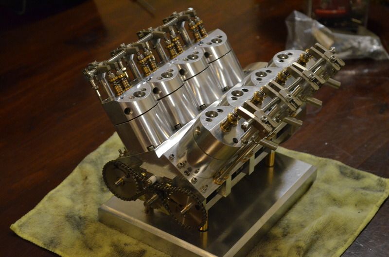
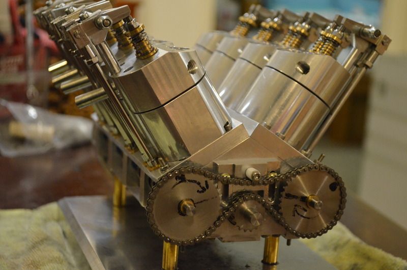
The chain needed a method of tensioning, so i made an adjustable bracket that had a PTFE wear surface for the chain. I made the bracket so i could add a spur gear to it at a later point. Engine is timed and tested it with an electric drill. All is good at the moment. Some of the glow plugs are leaking slightly, but i'm too worried to tighten the plugs that little extra in fear of stripping the threads.


https://youtu.be/V1Ip0PmOdVQ
 
The chain needed a method of tensioning, so i made an adjustable bracket that had a PTFE wear surface for the chain. I made the bracket so i could add a spur gear to it at a later point. Engine is timed and tested it with an electric drill. All is good at the moment. Some of the glow plugs are leaking slightly, but i'm too worried to tighten the plugs that little extra in fear of stripping the threads.

nice work wondering what is the intake going to look like
single or multiple carb ??
 
It's going to be a single carb setup. I will use stainless steel tube for the eight cylinders and bend them accordingly to meet in the middle to meet at a common manifold where the carb will be mounted. This is the plan anyway. Could change.
 
It's going to be a single carb setup. I will use stainless steel tube for the eight cylinders and bend them accordingly to meet in the middle to meet at a common manifold where the carb will be mounted. This is the plan anyway. Could change.


why stainless steel ??

home made carb or purchase one ??

what did you end out with firing order??
 
Chosen stainless because I want to stay with the silver coloured theme. If it proves to just be a pain when bending then I may change my mind. But so far I haven't had any dramas with it.

I've cheated with the carby and have purchased one. This will make things a lot easier especially considering that I haven't built an IC engine before. Im assuming there will be a lot of troubleshooting when it comes to starting.

I went with steves first firing order that he listed. Not for any particular reason, it was just the first in his list.
1-2-5-7-8-3-4-6
 
Back
Top