You are using an out of date browser. It may not display this or other websites correctly.
You should upgrade or use an alternative browser.
You should upgrade or use an alternative browser.
V8 nitro engine
- Thread starter Parksy
- Start date

Help Support Home Model Engine Machinist Forum:
This site may earn a commission from merchant affiliate
links, including eBay, Amazon, and others.
- Joined
- Jun 24, 2010
- Messages
- 2,455
- Reaction score
- 974
I'm watching closely & collecting tube bending ideas as we speak. The SS issues seem to be work hardening leading to kinks & cracks. But everyone's radius / tubing od / wall thickness / alloy / geometry & methodology is a bit different, so hard to compare apples & apples amongst the projects.
http://homepage2.nifty.com/modelicengine/k070402.htm
If you've done this already, would love to see your setup. Personally I've decided to ease into it with brake line tubing on my radial. The induction manifold has some funky curves. The exhaust stacks are just little curved stubs & could probably be SS. But aside from discoloration the brake tube should take the temp ok.
Parksy--I have been following your build for some time now, and I must say, your engine looks really good. You have certainly taken on an ambitious project, and I wish you success with it.----Brian in Canada
- Joined
- Dec 9, 2015
- Messages
- 327
- Reaction score
- 350
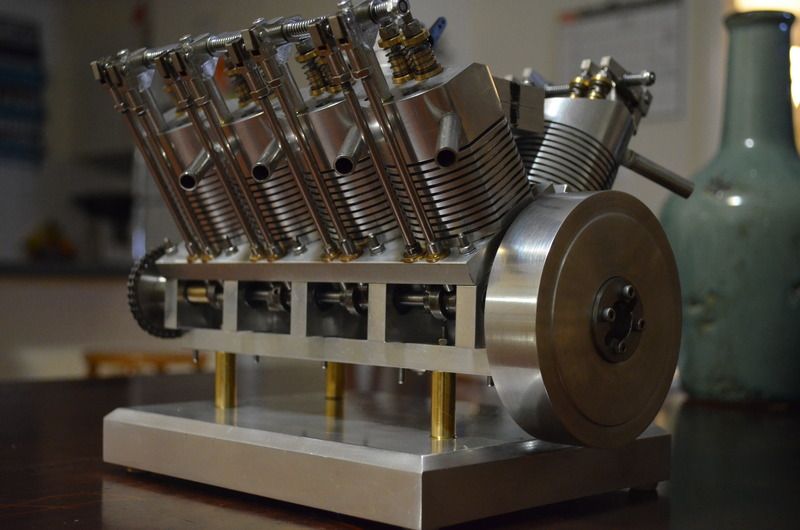
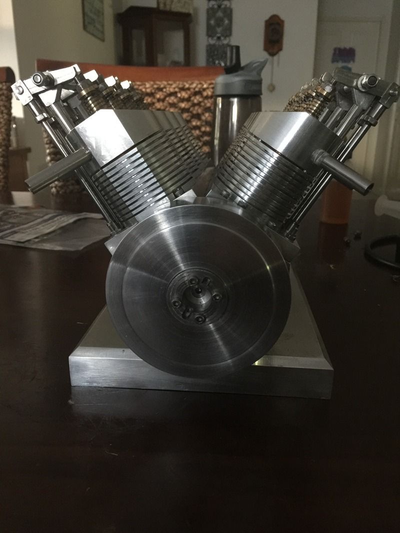
Spent the last few times in the shed tying up loose ends. I pulled the engine apart to sort out a couple of leaking valves. The majority were good, but one was particularly bad. My findings is fine lapping compound, followed by a thorough clean, then some metal polish then another thorough clean works fairly well. A simple clean seems to help a lot with valve seal.
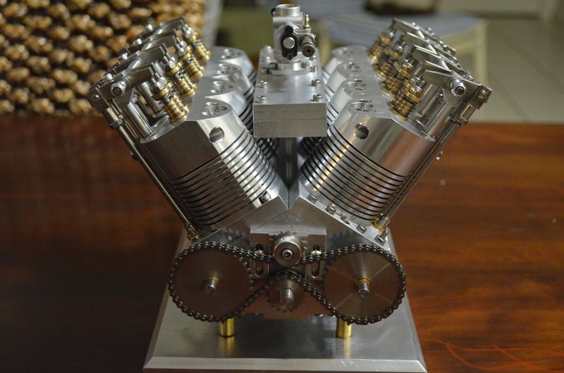
I chucked the heatsinks onto the rotary table and cut some fins using a slitting saw. I probably should have gone deeper and used a thicker blade, but we shall see. I must commend those who can achieve perfectly spaced and sized fins. Despite turning the controls with as much accuracy as possible, I still had a few unevenly spaced fins. But never mind, I like the look. Maybe I need to practice some more to improve accuracy.
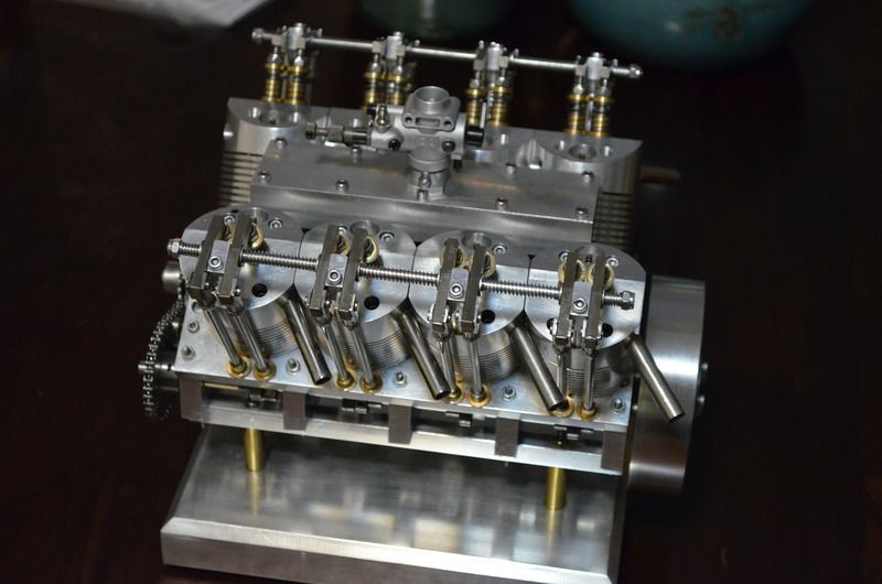
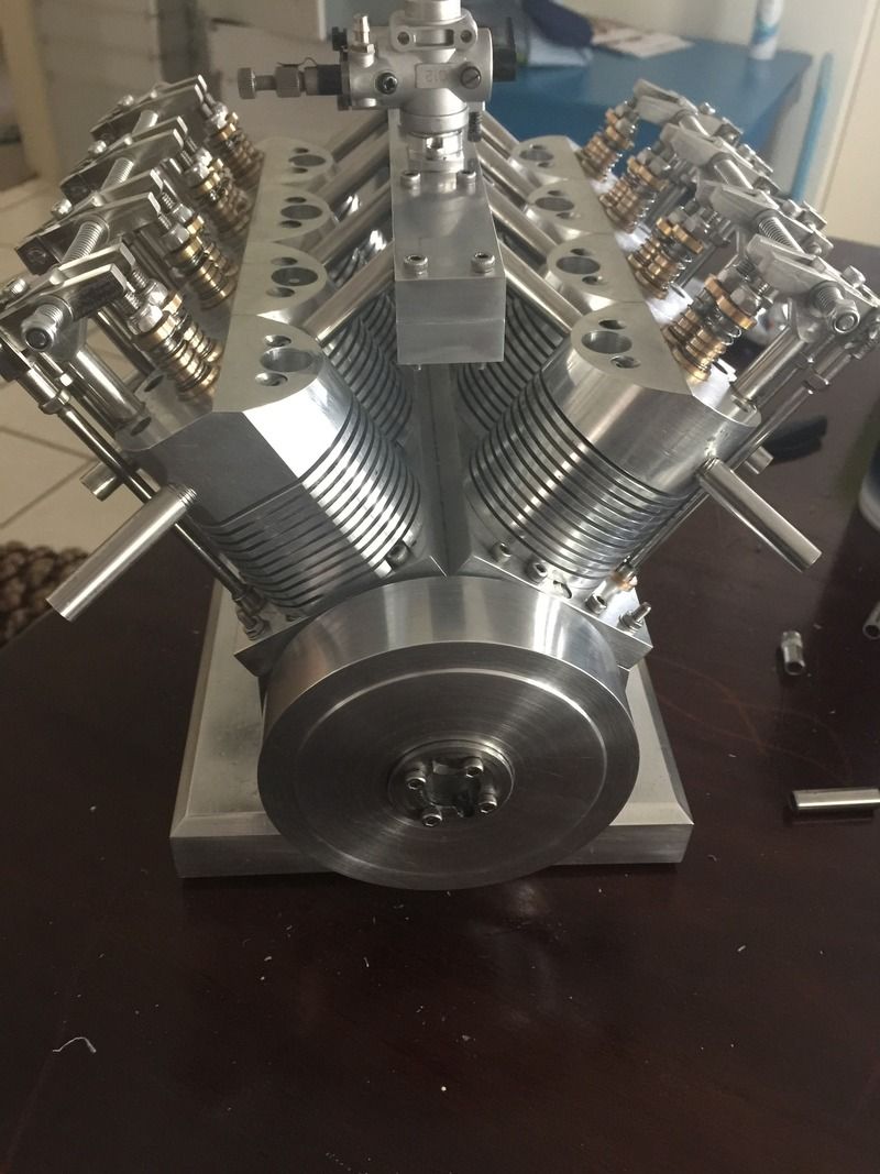
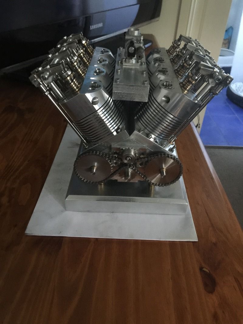
I've started on the intake. At the moment it consists of two plates clamped together, which I've hollowed out and made an adapter to fit a carburettor that I purchased from a hobby shop. The plan is to use stainless tube to attach it all together. I found some stainless tube from an eBay seller in Hong Kong that bends very well simply with a bender, and if I try hard enough, by hand. I'm just waiting for more to arrive.
Anyway here's some pics. Getting close.


$39.58
$49.99
Becker CAD 12 3D - professional CAD software for 2D + 3D design and modelling - for 3 PCs - 100% compatible with AutoCAD
momox Shop

$519.19
$699.00
FoxAlien Masuter Pro CNC Router Machine, Upgraded 3-Axis Engraving All-Metal Milling Machine for Wood Acrylic MDF Nylon Carving Cutting
FoxAlien Official

$45.99
Sunnytech Mini Hot Air Stirling Engine Motor Model Educational Toy Kits Electricity HA001
stirlingtechonline
![DreamPlan Home Design and Landscaping Software Free for Windows [PC Download]](https://m.media-amazon.com/images/I/51kvZH2dVLL._SL500_.jpg)
$0.00
DreamPlan Home Design and Landscaping Software Free for Windows [PC Download]
Amazon.com Services LLC

$99.99
AHS Outdoor Wood Boiler Yearly Maintenance Kit with Water Treatment - ProTech 300 & Test Kit
Alternative Heating & Supplies

$94.99
$109.99
AHS Woodmaster 4400 Maintenance Kit for Outdoor Wood Boiler Treatment
Alternative Heating & Supplies

$39.99
$49.99
Sunnytech Low Temperature Stirling Engine Motor Steam Heat Education Model Toy Kit For mechanical skills (LT001)
stirlingtechonline

$89.99
Outdoor Wood Boiler Water Treatment Rust Inhibitor- AmTech 300 & Test Kit
Alternative Heating & Supplies

$24.99
$34.99
Bowl Sander Tool Kit w/Dual Bearing Head & Hardwood Handle | 42PC Wood Sander Set | 2" Hook & Loop Sanding Disc Sandpaper Assortment | 1/4" Mandrel Bowl Sander for Woodturning | Wood Lathe Tools
Peachtree Woodworking Supply Inc
Cant wait to hear it pop. Keep us posted.
- Joined
- Jun 24, 2010
- Messages
- 2,455
- Reaction score
- 974
You've sure done some nice work there Parksy. Best of luck on the home stretch. And the finning looks good from over here!
The only thing I can pass on from my own RC nitro engine experience is the cylinders are actually relatively cool. They primarily see conductive heat from the heads. Finning is nice & certainly can only help. But the heads are where temperature is maximum. The cylinder barrels see this heat conductively. The heads see it almost directly being adjacent to combustion. In aircraft engines, head fins are still necessary to increase ambient surface area even though they receive perpetual cooling blast from propeller. In the stationary engines, with the absence of this airflow or liquid cooling, the fins become ginormous in order to dissipate this heat. I think this was discussed before but just saying keep an eye on it. Bad things happen when the heads cook.
I found some stainless tube from an eBay seller in Hong Kong that bends very well simply with a bender, and if I try hard enough, by hand
I'd love to hear what specific tubing you got, shapes you managed to bend, tooling pics etc.


- Joined
- Dec 9, 2015
- Messages
- 327
- Reaction score
- 350
Thanks Petertha. The temp side of things will get monitored religiously when (if) it starts. I've noticed that four stroke nitro engines aren't as radically finned as the two stroke versions, but if need be, I'll mill some fins into the heads to sort that out.
I'll post some updates on the stainless, but I'm still waiting for it to arrive. I have some 6mm tubing and it is just wonderful to bend using just a cheap eBay pipe bender. I've got some 8mm tube (1mm wall) on the way and I'm hoping it bends just as well.
Cheers
I'll post some updates on the stainless, but I'm still waiting for it to arrive. I have some 6mm tubing and it is just wonderful to bend using just a cheap eBay pipe bender. I've got some 8mm tube (1mm wall) on the way and I'm hoping it bends just as well.
Cheers
- Joined
- Jun 24, 2010
- Messages
- 2,455
- Reaction score
- 974
Sounds good. Re tubing, 'stainless' & 'easy' (bending) never seem to occur in the same sentence. Now I'm super curious what you got there. Keep us posted.
Cogsy
Well-Known Member
- Joined
- Dec 9, 2015
- Messages
- 327
- Reaction score
- 350
Thanks cogsy, I've also purchased some to experiment with.
It turns out I didn't purchase enough tube to practice with and I was worried that I would run out. I was able to bend it with the eBay pipe bender, but the radius was too large for what I wanted.
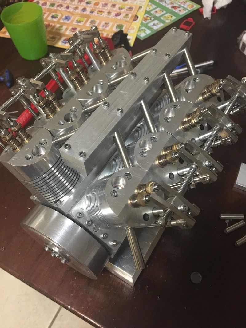
I found the intake setup to be quite a headache and head scratcher. Didn't make it easy for myself when I drilled the ports on the heads at such an awkward angle. Lesson learnt for next time.
Anyway, lots of measuring and drilling at very strange angles and I was able to come up with a setup that should hopefully work. The two halves are clamped together over the intake tubes which I plan to rtv silicon the halves together to seal it.
I'm not sure if I like the look at the moment, will have to see when it's completed.

- Joined
- Dec 9, 2015
- Messages
- 327
- Reaction score
- 350
- Joined
- Jun 24, 2010
- Messages
- 2,455
- Reaction score
- 974
The rule of thumb (4S or 2S glow) is that center of the tank should be about the center of carb fuel inlet spray bar that resides inside the venturi. But this has a lot of other (aircraft related) assumptions baked in that may or may not apply to your setup. But probably a good starting point in any event. This pic might serve as a good reference.
Mid tanking is basically trying to be a good 'average' position for a tank run. Its another way of saying averaging hydrostatic head, which is the vertical column of fuel in terms of equivalent pressure on the fuel stream = the distance between fuel level (top) and carb inlet (bottom). A full tank will have a slight positive head or higher fuel pressure & the engine may run slightly rich. A near empty tank can have low or no head & run leaner. Its not practical to be adjusting the needle as fuel level varies (and you generally cant in-flight), so a mid position is trying to average these end conditions so to speak.
If you elevate the exact same tank for example, you increase the head, which increases the fuel delivery pressure. We are talking low pressures psi-wise but actually quite significant in terms of needle valve setting & air/fuel ratio.
But typical RC flight vehicles deviate from stationary bench engines. As the model maneuvers the head can change quite dramatically. Just imagine this same picture rotating to different orientations as in climb or dive & now where is the fuel top & bottom. So its also common to put a pressure tap on the exhaust manifold & pipe this to the tank which gives a bit more positive pressure boost which is additive to fuel hydrostatic pressure.
Your stationary engine wont have these complicating 'flight' issues, so it really boils down to finding a reasonable tank position & needle valve setting combination that gives a good run & then basically just monitoring fuel level & actual running. The carb of course is seeing slight vacuum pressure from venturi throat airflow & manifold pressure so it can draw fuel at a slightly lower level (within reason). Similarly the tank can be elevated slightly so long as the needle valve can be screwed in & still meter properly. But this also has practical limits. If the tank is too high, fuel can also free flow into the carb / manifold / cylinders especially if engine doesn't start right away. This risks hydraulic locking & bad things can happen with an electric starter. So good to have a shut-off valve or simple line pinch between tank & carb in any event.

- Joined
- Jun 24, 2010
- Messages
- 2,455
- Reaction score
- 974
Ohrdorf V12


- Joined
- Dec 9, 2015
- Messages
- 327
- Reaction score
- 350
need to wire up the glow plugs. I have four glow plug drivers and I did try firing with just four. Got a few pops and hot cylinders, but no running. Am I kidding myself trying to run it on four cylinders?
Cogsy
Well-Known Member
Well....I once accidentally fired up the 351 Cleveland V8 in my car with 4 leads off and it was difficult to start and seemed like it was running out of fuel - then I remember the 4 plug leads. I'm not saying yours wouldn't run, but it'll be much easier to start on all 8.
- Joined
- Jan 24, 2009
- Messages
- 554
- Reaction score
- 124
need to wire up the glow plugs. I have four glow plug drivers and I did try firing with just four. Got a few pops and hot cylinders, but no running. Am I kidding myself trying to run it on four cylinders?
A lot of friction to fight but I don't think it would hurt anything to try.:hDe:
Pete
Similar threads
- Replies
- 5
- Views
- 561


