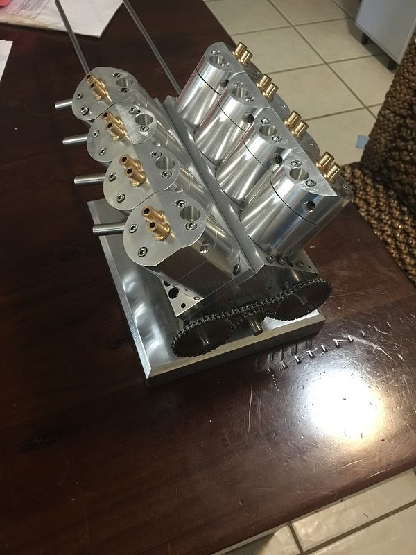
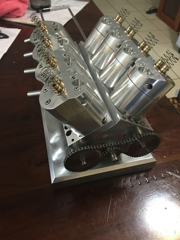
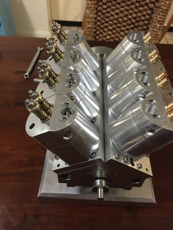
V8 nitro engine

Home Model Engine Machinist Forum

Help Support Home Model Engine Machinist Forum:

This site may earn a commission from merchant affiliate links, including eBay, Amazon, and others.
Had issues with making valves today. The stainless just wanted to flex too much, even if I used a live center on the end. Was ending up with uneven thicknesses across the stem.

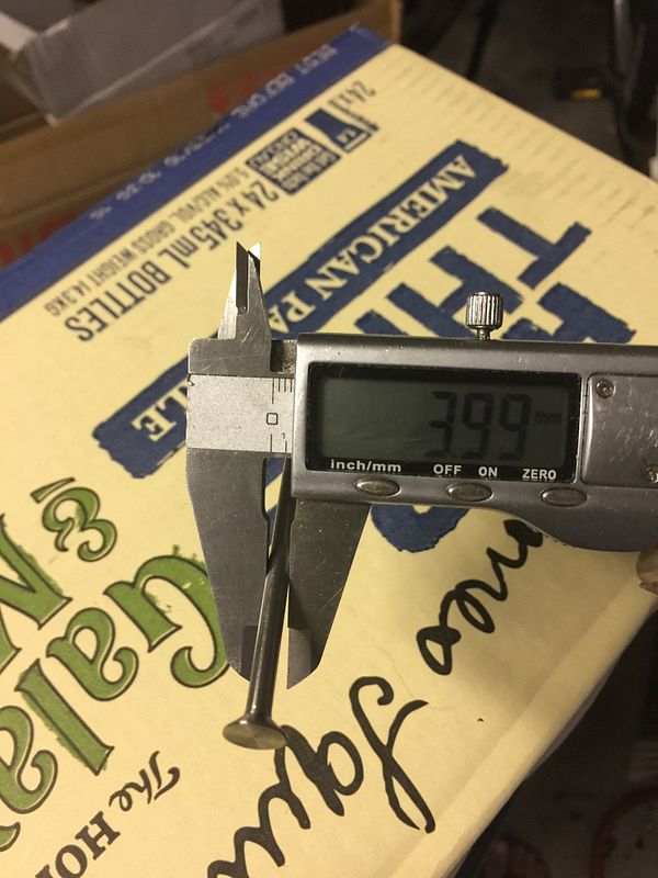
I set the compound slide on the lathe to 40 degrees and cut the valve seat. Would I be correct in simply setting it to 40 degrees to cut the opposite angle for the actual valve? Or will this angle be 50 degrees? I

re valve alloy, I ended up trying 416 based on machinability charts like this. I needed to buy material anyway so figured try & stack the deck in my favor. I also tried (I think) 303, didn't seem radically different at least for this part & my tooling/technique. Shades of crappy :) I learned you cant creep up on it to skiff off the last thou because it can work harden (might be part of your issue in disguise?). Really sharp tools performed best.
https://www.google.ca/search?q=machinability+comparison+stainless&biw=1642&bih=999&tbm=isch&tbo=u&source=univ&sa=X&ved=0ahUKEwiA9vzxvqfKAhVMxGMKHQDZCb8QsAQIOQ#imgrc=SgqDPfJRlrWs0M%3A

Re finishing, I worked my ~ 0.004" roughish turned finish down with hard backed emory paper sticks & miked along the stem until it was in the sizing range for homebrew lap post #9. My tool worked quite well but of course the tailstock support chunk must be removed to slide the lap on.
http://www.homemodelenginemachinist.com/showthread.php?t=24516

I like the looks of this self made mini clamp hone. Its on my list of tools to make & try. My thought is make it say 50-75% the valve stem length so I can traverse & correct any diameter changes? http://philsradial.blogspot.ca/2012/02/valves.html

ps- I'm a rookie, just stumbling behind what I respectfully steal l from others. Check out Terry's radial build posts in particular. There are other good ones too, just that comes to mind immediately on valve stuff.

re seat angle, I think the common mode is to strive for cage/valve face equal angles but a proper & very thin contact line for seal. How this is achieved is documented in other builds,or others can chime in. FWIW I measured a commercial RC 4S engine at 0.015-0.020" chamfer on the valve cup as I recall.
 
When I have made valves, I machine the stem in steps of about 10mm length at a time. This helps prevent the stem from pushing away as you machine it, when final length has been reached the use of some fine emery backed up by a file evens out any blips.

Paul.
 
I make valves using O1 drill rod (silver steel). I also get taper in the stem but only 1 or 2 thousands. I then work them with sand paper until they are straight. I doesn't take but 5 minutes to straighten them out. Patience and frequent measuring and a little practice and you can get them within just a 1 or 2 tenths.
 
Thank you all! This helps me a lot! Has anyone used a steady rest for these kinds of things? Do they only get used on the final pass? I don't properly know how to use them, because if the surface is uneven, then it will force the material into the cutting tip unevenly. And do they need adjusting after every pass?
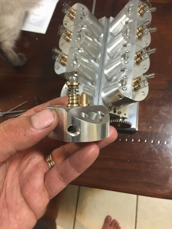
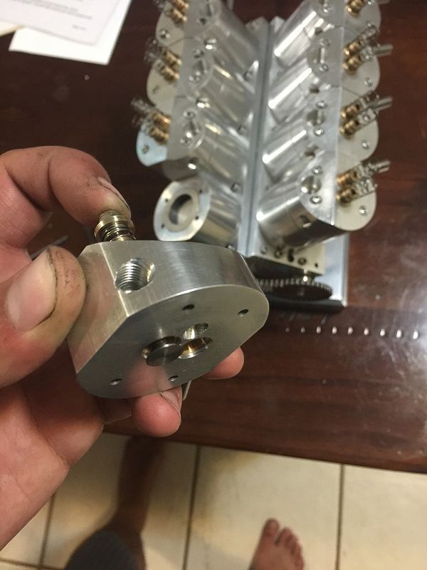
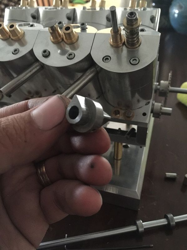
Anyway, more progress today. Milled a hole into each cage, then pressed them into the heads. I made a couple of valves, both with different seat angles and they both seal fine?? The valves are rubbish because I'm not happy with the stems, but I'll employ some of the methods mentioned here.
Cheers all

 
Attempted another valve and it turned out OK. But I threaded the end and I'm not sure if I like it or not. How do the E-clips hold up in this application?
I tested the valve by blowing as hard as I could into the port and all is good at the moment. Is this acceptable for an engine to run? I haven't lapped it and I'm sure there's probably more acceptable methods of testing it.

 
I make valves using O1 drill rod (silver steel).

Now that's good info to know Steve. I've often wondered what the rationale behind stainless was to begin with. Have you tried both & concluded O1 was better for any particular reason? Or you just tried it, worked well & called it good? While we're at it, what is your valve cage/seat material of choice in conjunction with O1?
 
Attempted another valve and it turned out OK. But I threaded the end and I'm not sure if I like it or not. How do the E-clips hold up in this application?

E clips on valve stems are fine, the ones that I have made have used a washer with a shallow recess to contain the E clip to stop it slipping off.

Paul.
 
Cheers Paul! That is good to know.

I made a couple of valves today and they turned out great! I used a steady rest and was able to machine the valves along the entire length without supporting the end. Worked well. I think when using the steady rest, it requires a lot of practice. But I think I'm getting better. I might mod mine and incorporate ball bearings. At least this will give me an indication on whether it's doing its job or not.

Cheers
 
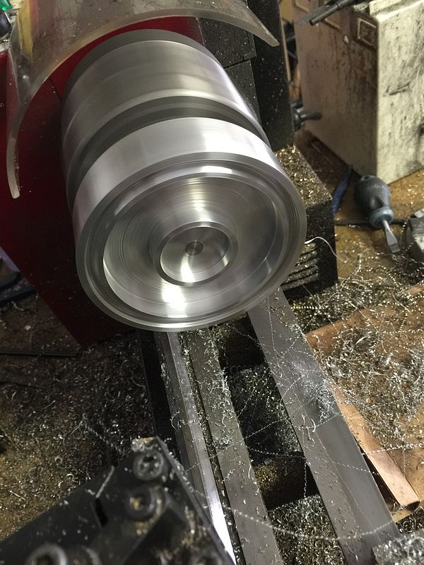
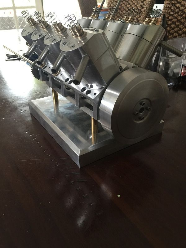
Finished the flywheel today, well mostly. It started as flat aluminium bar that I turned down on the lathe. Cheaper than buying large diameter rod. I intend to fill the inside edge with lead to give it more weight. I still need to do this, but now I can at least spin the engine by hand. Am I strange for blocking the ports and spinning the engine to make popping sounds? Can't wait to hear this thing roar into life(hopefully).


Had a go at making cams. Never done anything like this before but the process was very straight forward and I remember seeing it done on the mill with a rotary table. Worked well. Made out of tool steel. Nothing radical with regards to timing. I milled the exhaust lobe first, then 90 degrees later, milled the intake. Sound about right?

 
Mounted the Dremel onto the tool post holder and used this to grind the taper out of the valves and I'm totally impressed. It worked very well and it's easy to get accurate.

Made 2 in a row successfully. On a roll!
 
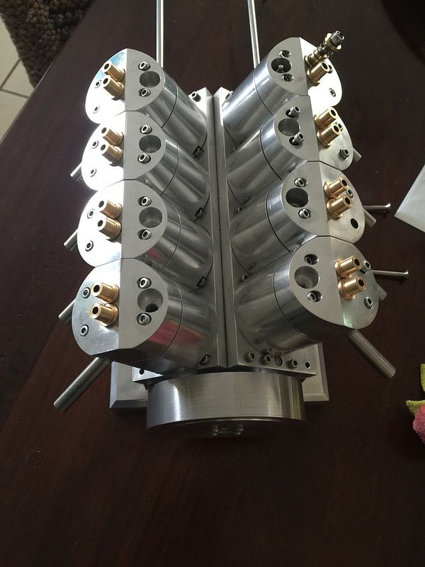
First 8 valves completed and installed. Decided to just use a nyloc nut as the fastening device. No fear of these coming off. I've loosely installed some glow plugs to see what kind of compression it's producing and despite the air hissing out of the glow plug holes, it's bouncy. When it comes to the compression side of things, I didn't give much thought about it except to leave little to no clearance from the piston to the head and utilise a gasket to achieve what ever required height and compression.

http://youtu.be/RH8PjumJBBA
 
I didn't give much thought about it except to leave little to no clearance from the piston to the head and utilise a gasket to achieve what ever required height and compression.

I don't think the piston 'closeness' is a huge issue itself, but the compression ratio is for typical methanol/glow. What do you figure your CR (max) is now without gasket shims?
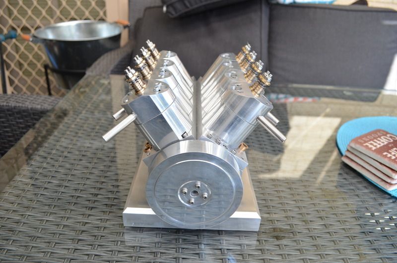
 
Without the shims, according to the maths, it's about 9.62:1. With a 0.5mm shim, this takes it down to 8.2:1.
 
Was wondering what everyone does for carburation for these types of engines? Do you make your own carbies? I haven't done much research on vapour carburettors, but the concept is simple and would be simple to make. Do these have rapid throttle response compared to a conventional carburettor?
 
Thank you Petertha.

I don't suppose I could get this thread moved to a more appropriate section of the forum(ie build thread)?

Cheers
 
Last edited by a moderator:
Gday all

I'm getting my head around cam timings by looking at drawings and I think it makes sense to me. I found a drawing by George D.Britnell which shows intake total open of 220 degrees, exhaust total open of 230 degrees (crank degrees btw) and valve lobe separation of 97.5 degrees. This I understand and should be able to construct, I am just curious if this would suit a nitro v8 engine. I'm not after a revving monster, more a slow runner.
How does the lobe separation and valve open periods effect the engine performance?
Thank you all. My engine knowledge is growing vastly thanks to this page and its members.

Andy

 
Back
Top