Stephenson's Rocket--Working Model

Home Model Engine Machinist Forum

Help Support Home Model Engine Machinist Forum:

This site may earn a commission from merchant affiliate links, including eBay, Amazon, and others.
So now my engine(s) have two of the fanciest connecting rods that I've ever made. They turned out very nice, although there seemed to be a ton of work in them. The con rods were the last two pieces needed to make my engine set-up run. Now I have to spend time working out all the "stiffness" so I can get things to run on about 15 to 20 psi of air.
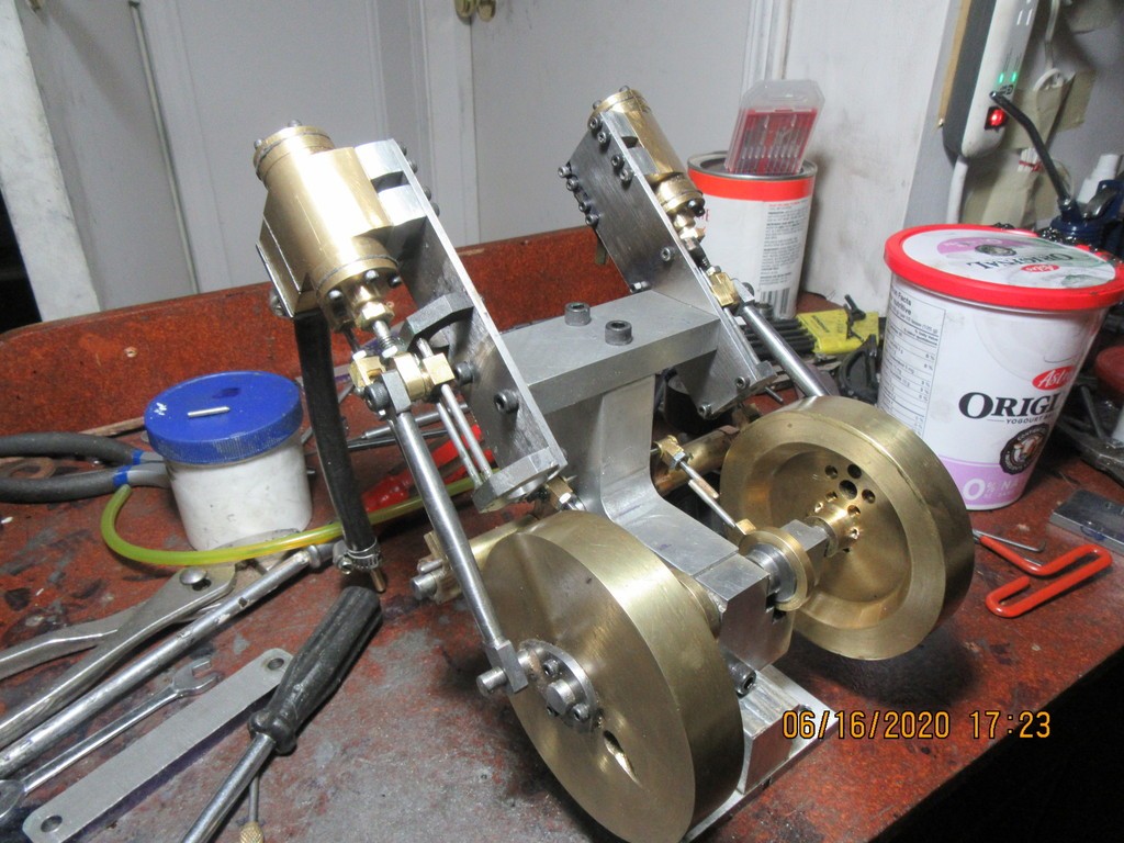
dwjgcE.jpg
 
This afternoon I hooked up air to the second engine and it ran quite nicely. I have to go to the hardware store tomorrow and buy some very small gear clamps. I will make up a tee in the morning so one feed line can supply air to both engines. When the engines are ran independently, they are running on the strength of one piston only. When I run the two engines together, they will have the power of two pistons, so should require only half the air pressure I am currently using. As soon as I have both engines running together, I will oil everything up well and let them run for an hour. This initial run will get rid of any "stickiness" in the system.
 
I spent a couple of hours chasing down "tight spots" in the system this afternoon. That is done basically by process of elimination.--Keep taking parts off one at a time until the main shaft rotates freely--open up clearances on the offending part, put it back on, then repeat. Eventually you get to a point where the main shaft rotates without any binding.--The result?---An engine set that runs consistently at 20 psi. There will be no more posts now, until I start fabricating the chassis which the engines bolt to.--And, the cranks are offset 90 degrees to give self starting capability
 
Brian,

Like all your engines, this one is running well and looks good. I'll be following the locomotive build and I have no doubt that it will come out well, too.

--ShopShoe
 
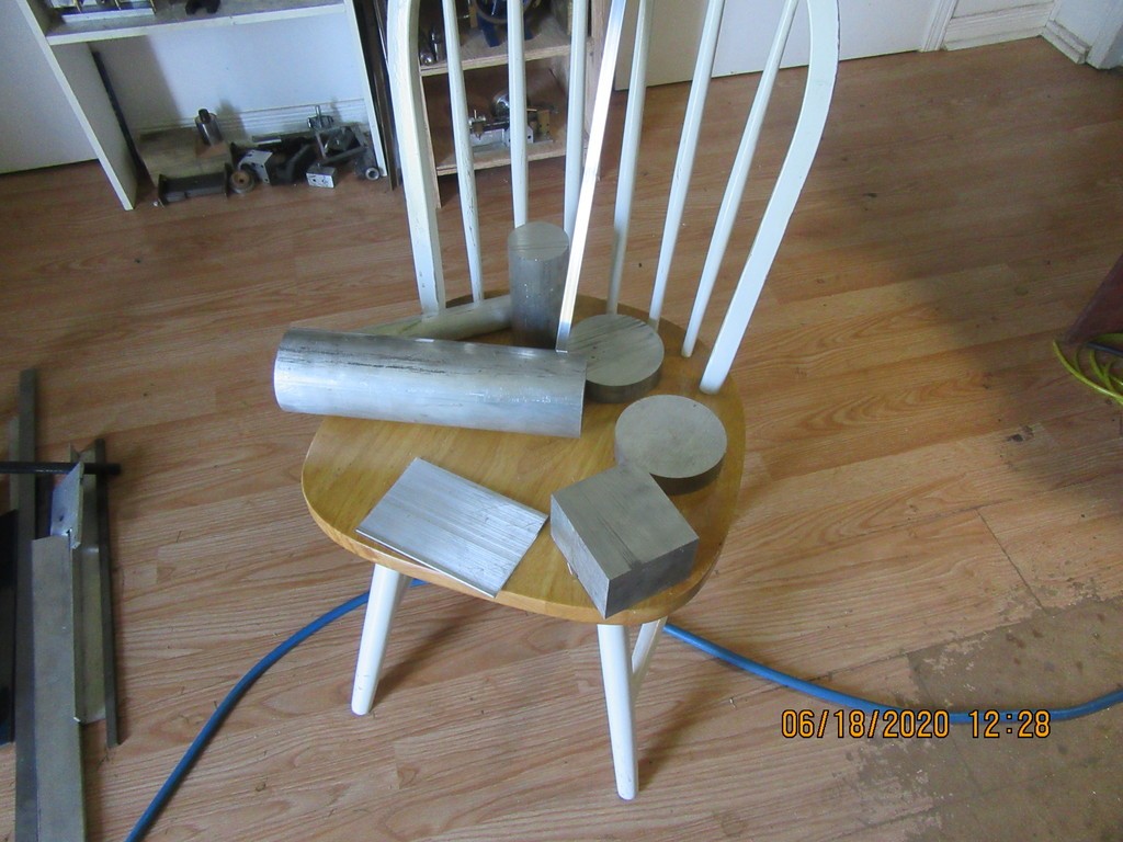
And here we have the rest of the material to build the chassis with.---Except for the big drive-wheels. If you are wondering, that's $97 worth of aluminum setting on the chair. I enjoyed a machining free morning. When I designed the chassis, I just thru in all the shapes with no real attention paid to how they all go together. This morning I started "finessing" all of the parts to add in the threads, bolt holes, etcetera.
mvBuSo.jpg
 
Where to begin, Where to begin??? I think the simplest part is going to be the smoke-stack.---And no, I haven't got the faintest idea of how to make that frilly part that fits on top of the stack. I think to look right, I'm really going to have to make it, but I haven't got a clue as to how.
jFr4de.jpg
 
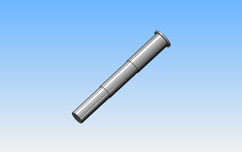
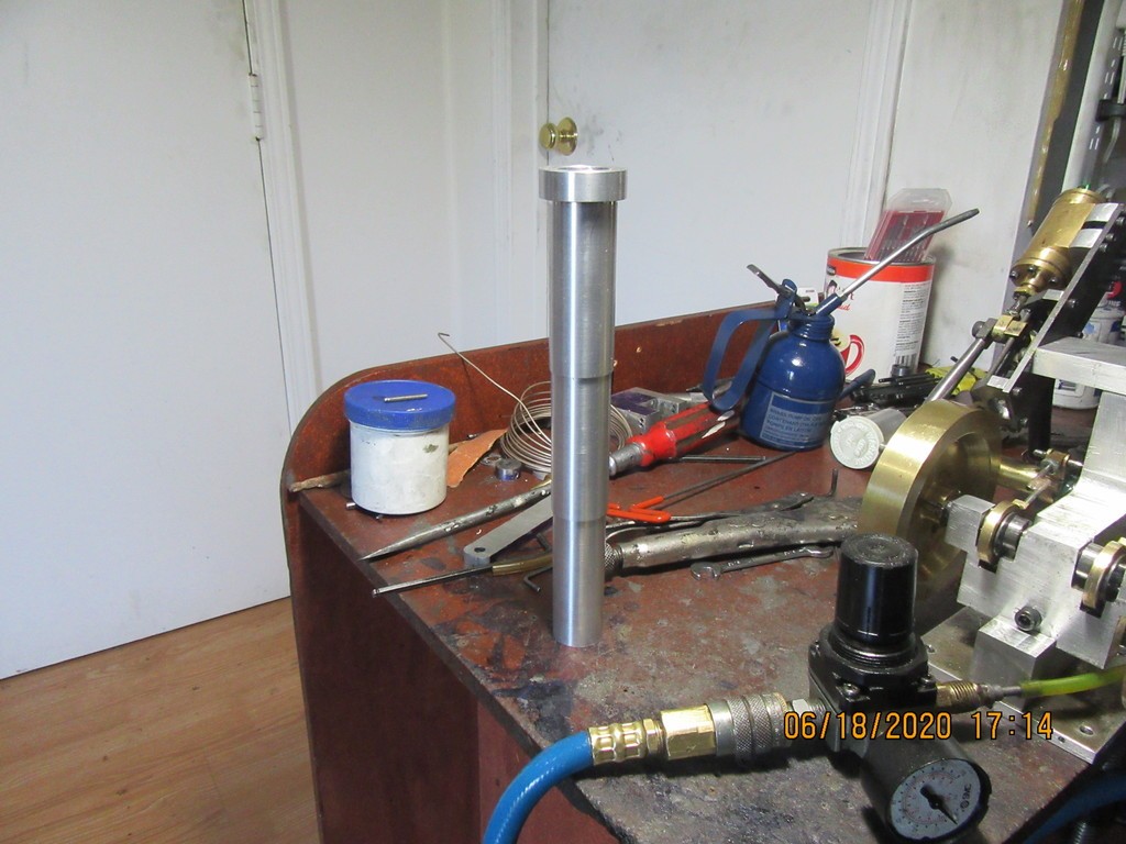
And yes, my darlings--We have a smokestack!! Turned and drilled from 1 1/2" solid. By the time I was finished the swarf in my tiny shop was knee deep.
VfLvtX.jpg
 
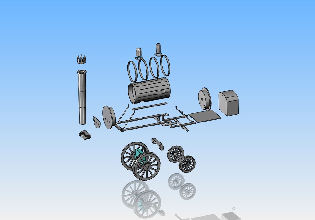
This is where I am going now. An "exploded" view gives some pretty good insight of what lays ahead with the chassis build. the engine assemblies don't appear here.
zlpwI0.jpg
 
brian, the frilly cap on the smoke stack - here is how i made it on my little boiler, i took piece of brass sheet i picked up in the hobby bits section at lowes and i measured and drilled little holes evenly spaced then cut it out with a exacto knife and soldered it to the top of the pipe. the holes drilled were the bottom of each "V" cut i made wihth the knfie. then i just bent the tips of it out a little. a crude hand drawing of what i mean in the last photo.

hope that helps some


1592573831784.png


1592573871319.png


1592573995652.png
 
or, another thought on the topper, if you export that drawing to an stl format i could 3d plastic print it for you. since its air driven and not steam driven then heat wouldnt be a factor? a little sanding, a little red bondo spot putty and some paint and 3d printed parts dont look printed any more, gets rid of the lines in the part asocciated with 3d printed pieces
 
just an aluminum plate, using the feed dials I domed it and then file/sand paper to smoothe that out. its just a cover plate screwed on it doesn't hold any preasure there. on inside it is silver soldered. all pressure connections are silver soldered. non preasure is just soft soldered. the brass is about 3/8 thick walled heavy. I got it out of an oxygen concentrator machine that people with copd or breathing problems use. the scrap yard had several that were scrapped so I picked up a couple.
 
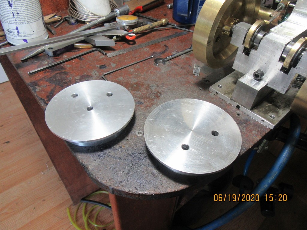
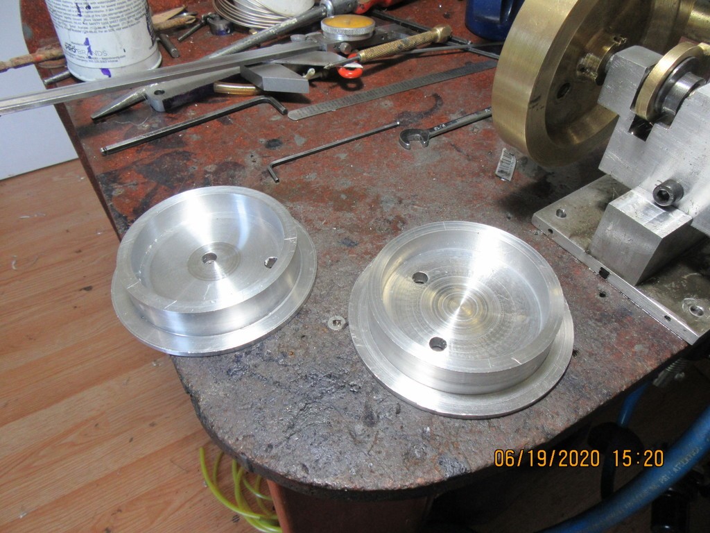
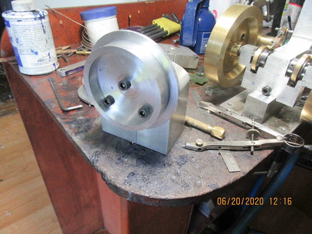
Today's entertainment was end-plates for the boiler. There is nothing really special here, just a lot of machining. If you have a good eye you will see that one endplate only has two holes, as opposed to having three holes as shown in the exploded view. As I was about to drill the third hole in the second plate, I thought "Jeez, I'm not lifting elephants with this thing---2 holes will be enough." One endplate will support the smoke-stack and the other is bolted to the fire-box. The bolt heads will be on the inside where nobody will see them---so---clearance holes in the endplates, threads in the fire-box and smoke-stack support. You will also see that the design evolves as I make the parts. The end plates in the model were a lot of mass for no good reason. I relieved a lot of the center of each endplate, and then went in and modified the drawings.
SocwHk.jpg

tz3Yrk.jpg
 
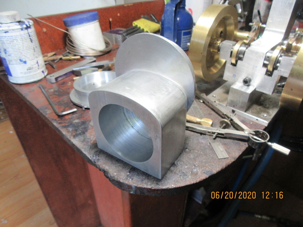
This morning yielded a fire box. I decided to carve out most of the interior to make it a lot lighter, and I made it round so I can fit a nice fire box door. The only problem with buying off-cuts at my metal supplier is that sometimes trimming the off-cut down to the size needed to make the part is more work than making the part.
Vndtf1.jpg

O5SiKy.jpg
 
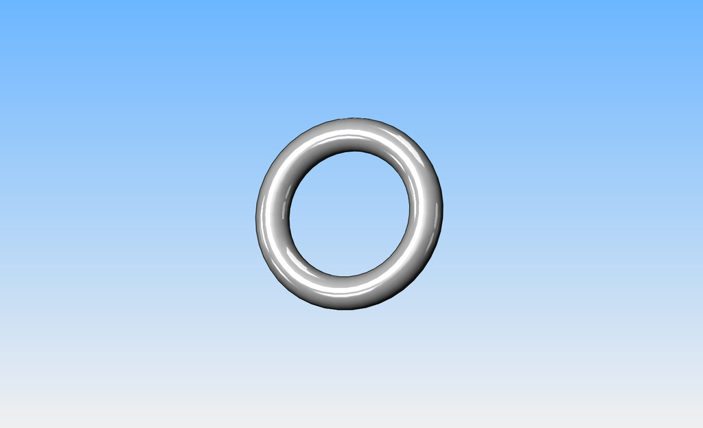
Does anyone know where I can buy this? I've seen them before but I can't remember where. They are basically a small diameter tube (or even solid would do) about 5/16" to 3/8" diameter formed into a continuous circle about 1 1/2" diameter. Model builders cut portions of them away from the circle to use as elbows in model piping.---Brian
3eMZKs.jpg
 

Latest posts

Back
Top