Stephenson's Rocket--Working Model

Home Model Engine Machinist Forum

Help Support Home Model Engine Machinist Forum:

This site may earn a commission from merchant affiliate links, including eBay, Amazon, and others.
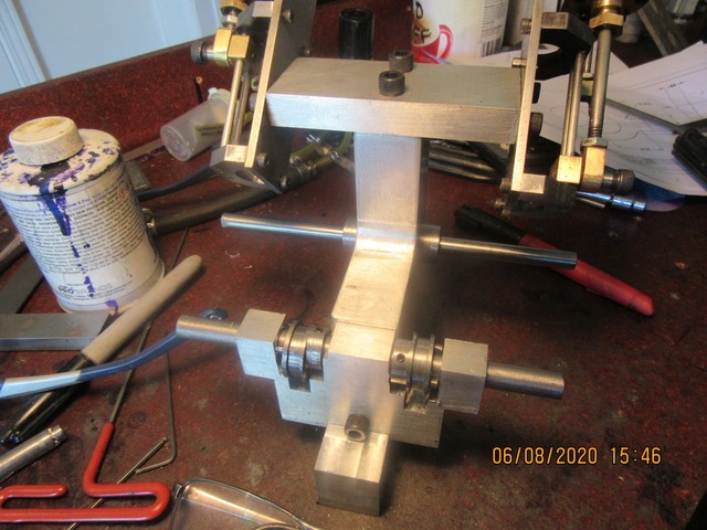
This morning I got up and made the eccentric strap retaining plates (for the second time) and bolted them to the eccentrics. All looks good---I am going to turn a few thou off the heads of the #4 shcs to clear the shaft better (they are mounted to a dummy shaft in the picture).I'm not certain that it shows in the picture, but there is a #5 set screw in the hub area of each eccentric, which fixes them to the shaft.
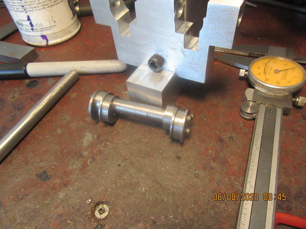
TAXygv.jpg
 
Hi Brian,
I understand it just a representation of the Rocket locomotive but I think it will really enhance the engine to use hex head bolts rather than the socket head screws.
gbritnell
 
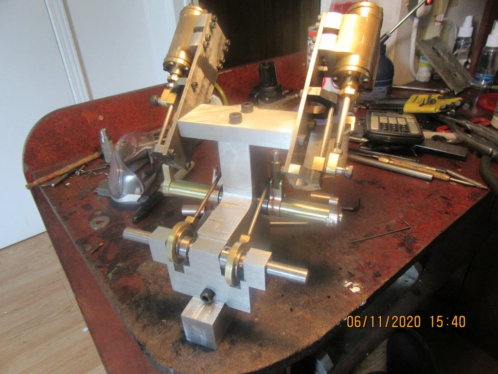
This picture shows the eccentrics with the eccentric strap retaining plates bolted on, setting in place on the drive axle. You can see the cut away portion of the axle mounting plate that is clearance for the eccentric strap as the axle rotates. I went by Princess Auto today to buy some oilite bronze bushings to press into place in the axle mounting plate, but the people were lined up all the way around the building, keeping their 6 foot distance apart for Covid. I didn't bother stopping--I'll either make my own bushings or figure something else out.
vjNzma.jpg
 
Hi George---I'm glad that you stopped by for a look. I like the look of socket head capscrews. You're right---it would look more "authentic" if I used hex head bolts. I'm not going for an authentic look---this is more a "something to do" job than anything.---Brian
 
And today, I whittled out eccentric straps. Not difficult, but time consuming. There are actually two or three ways to do eccentrics. The way I have done with two piece bolt together eccentrics and one piece eccentric straps, or you can do one piece eccentrics and two piece eccentric straps. I don't know which is easiest. I've made them both ways, and it ends up being about the same amount of work.
HNJdo5.jpg

 
This morning I put on my mask, stood in line, and bought four oilite bronze bushings that were 3/8" i.d. x 1/2" o.d. ---This afternoon I determined that there is no way in Hell that you can turn the outside diameter down to 7/16". Doesn't matter how sharp the cutting tool is, doesn't matter what speed you run the lathe at.--The bushings crumble before you can get them down to a 1/32" wall thickness. They were the only bushings available locally. Pooop!!!
 
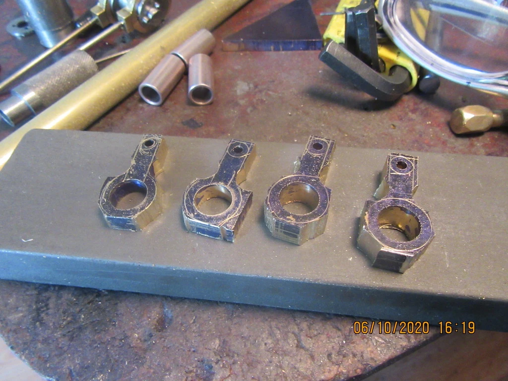
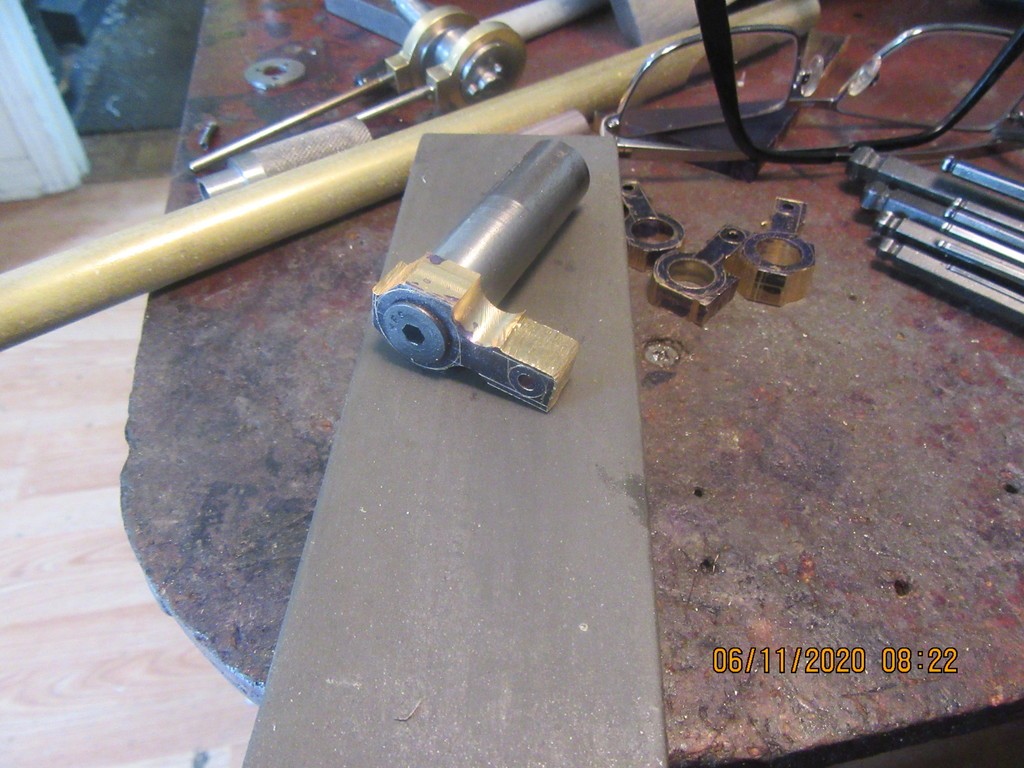
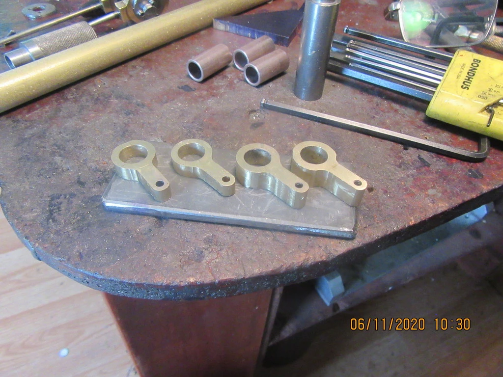
I have four little pivot arms for the eccentrics. They were laid out on a piece of brass plate, drilled, reamed, and rough cut on the bandsaw. On bigger pieces I generally go right from the bandsaw to my vertical belt sanding machine and finish them off "by eye". I can't do that on pieces this small, so they will be machine finished using my milling machine and rotary table. I will have to make up some simple fixturing to hold them, and will post pictures of "in process" work.
RBCLtk.jpg
 
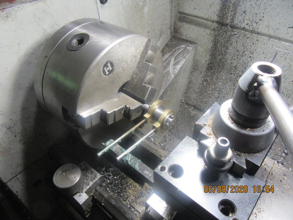
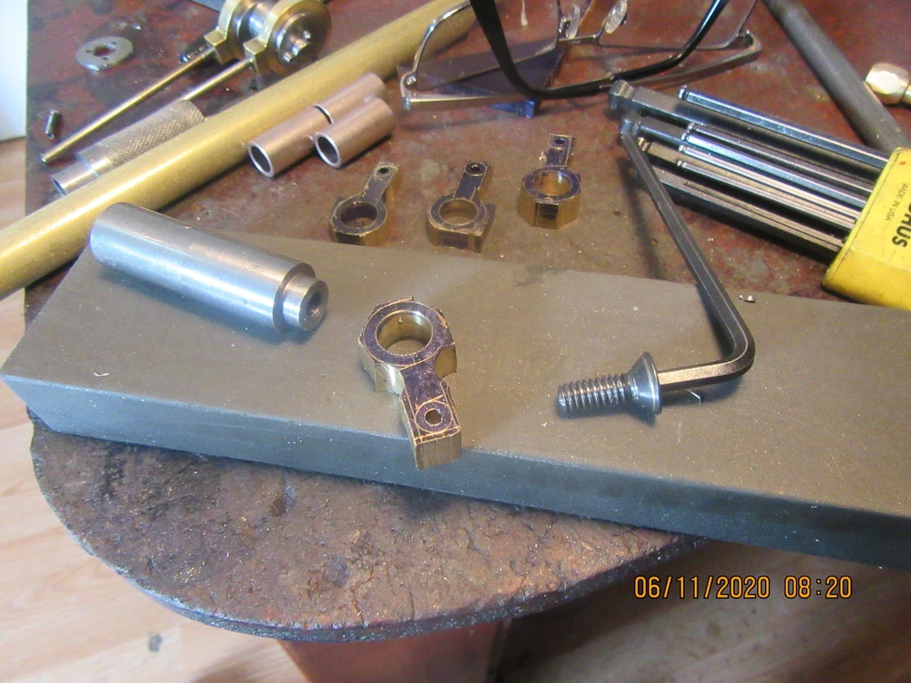
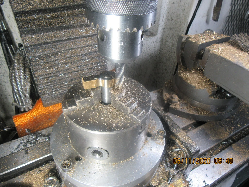
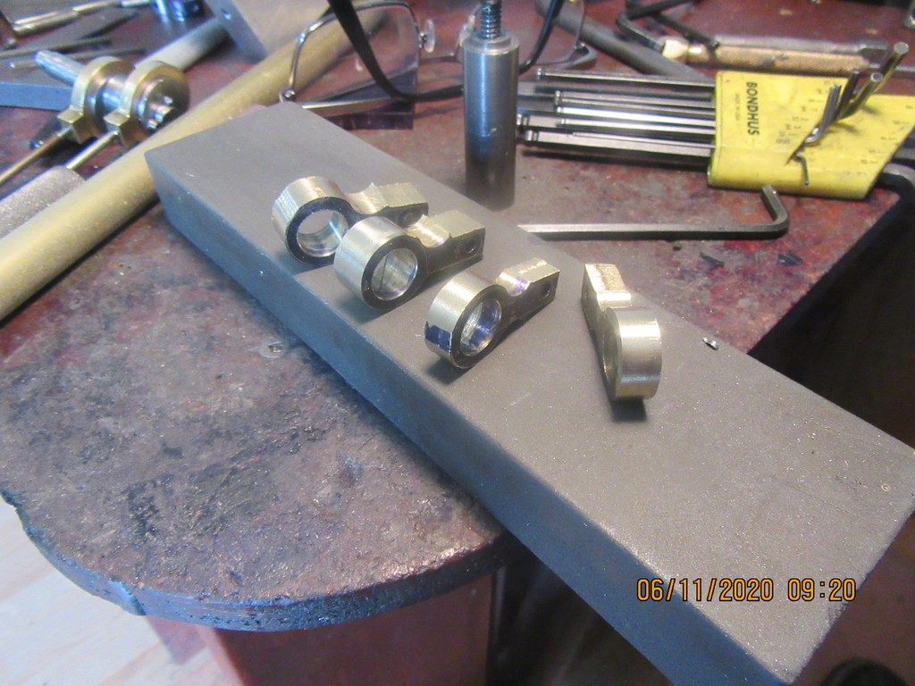
The pivot arms are completely finished (I think the wide ones get a slot added yet). These were too small for me to hand finish "by eye", so I made up a mandrel with a 7/16" diameter register on the end of it, over which the levers would fit (they are 7/16" reamed hole). The o.d. of the lever bodies is 11/16" diameter, the outside diameter of the fixture is 5/8". The flat head capscrew is 0.493" diameter, so it will not pass thru the bore on the brass bits. When the capscrew is cinched down tight, it captures the brass bit so it can not rotate. It is then a simple matter to hold the fixture in the 3 jaw chuck on my rotary table, set up the appropriate offsets, then turn the handle on the rotary table to spin the chuck around, while the endmill cuts with it's side to finish off the o.d. of the brass pieces.
oH3B0D.jpg

gwZU98.jpg

dBISEK.jpg

SD88iX.jpg

mlXgkE.jpg
 
Today we move a little farther towards a running engine. The eccentric pivot levers (for lack of a better thing to call them) are finished and in place on the engine. I still have to make up a few connecting links and rod ends, and figure out what to use for a flywheel, but it's getting close to "run time".
3DmBCZ.jpg
 
I didn't work on the Rocket today. My "man chores" have been piling up for the last month while I played in my shop, so today was the day to --cut the lawn---fill in the hole that a groundhog tunneled under my patio stones and relay the stone---sweep up a terrible accumulation of swarf from my machine shop----clean up all of my outer garage---and put about a thousand tools away. I have been wondering just what I would use for a flywheel on these engines mounted on the test stand. When the engines are assembled to the train chassis, the big front wheels become the flywheels. However, I'm not ready to start making the wheels yet, and I didn't want to buy material to make a temporary flywheel from. Then I realized that I have been slowly pirating parts away from the original Rupnow Engine that I designed and built about 10 or 12 years ago, and that it had a pair of lovely brass flywheels that I can use.
kVF5HC.jpg
 
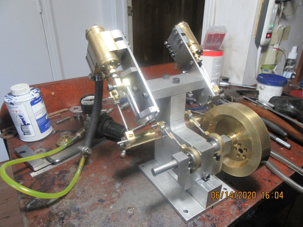
The engine test stand has gained a footplate. It was getting top heavy and the foot plate gives me something I can attach to my desk-top to keep it from toppling over. All of the linkages have been completed and set roughly to the correct length. I have borrowed a flywheel from one of my early engines that is slowly being robbed of parts. I got tired of trying to source oilite bushings for the main drivewheel shaft, so machined some from brass and Loctited them in place. I have tested things to the point that when I turn the flywheel by hand the eccentrics operate the slide valves in the steam-chest which makes the cylinders extend and retract. They are still very stiff and "oinky", but I will chase down interferences and maybe put a 0.005" shim under one cylinder. Tomorrow I will machine the connecting rods and the piece they connect to at the drive axle.
chVfgm.jpg
 
After the time spent with a career in carpentry and then one as a dentist, I wish I had the time and skill to make these things myself but I certainly love watching those who can.

If I did I'd make the ME and also Mary Beam engines for which I have casting sets. I need to put them on ebay and start clearing out the basement.
 
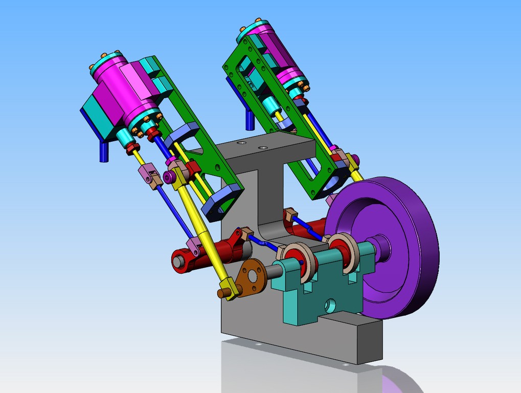
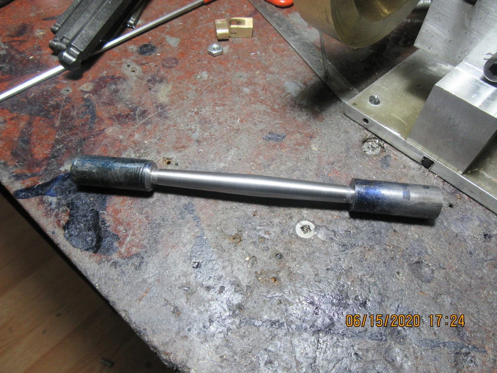
I'm trying something I haven't done before. This is the connecting rod which goes to the flywheel on each engine. As designed (you can see it in the solid models) it is 0.350" diameter at the center with a 4 degree included taper out to each end, where it becomes flat. It is easy to do in CAD, considerably more difficult in real steel. The issue is that I am starting with cold rolled steel, and have never really found a way to machine cold rolled steel without leaving a lot of lines and ridges. I am machining with my top slide set over 2 degrees, so I can't use automatic feed, so it's hand crank all the way on both sides of center and use lots of cutting oil.That's okay, but there is a lot of sanding after the fact with #180 and #220 grit sanding strips. If I get the ends machined flat and cut to length, I think these rods will look quite elegant.
wHh1Hc.jpg
 
Andy---Due to the fact that the engines are brand new and there is still a lot of binding to be sorted thru, it's running on about 80 psi of air. I like to see them run on about 15 psi after all the tight spots have been eliminated.
 
Gotcha. On the connecting rods, don't forget the possibility of using a file - sometimes I reach for the emory paper, and only later realize a file would be a better choice. :)
 

Latest posts

Back
Top