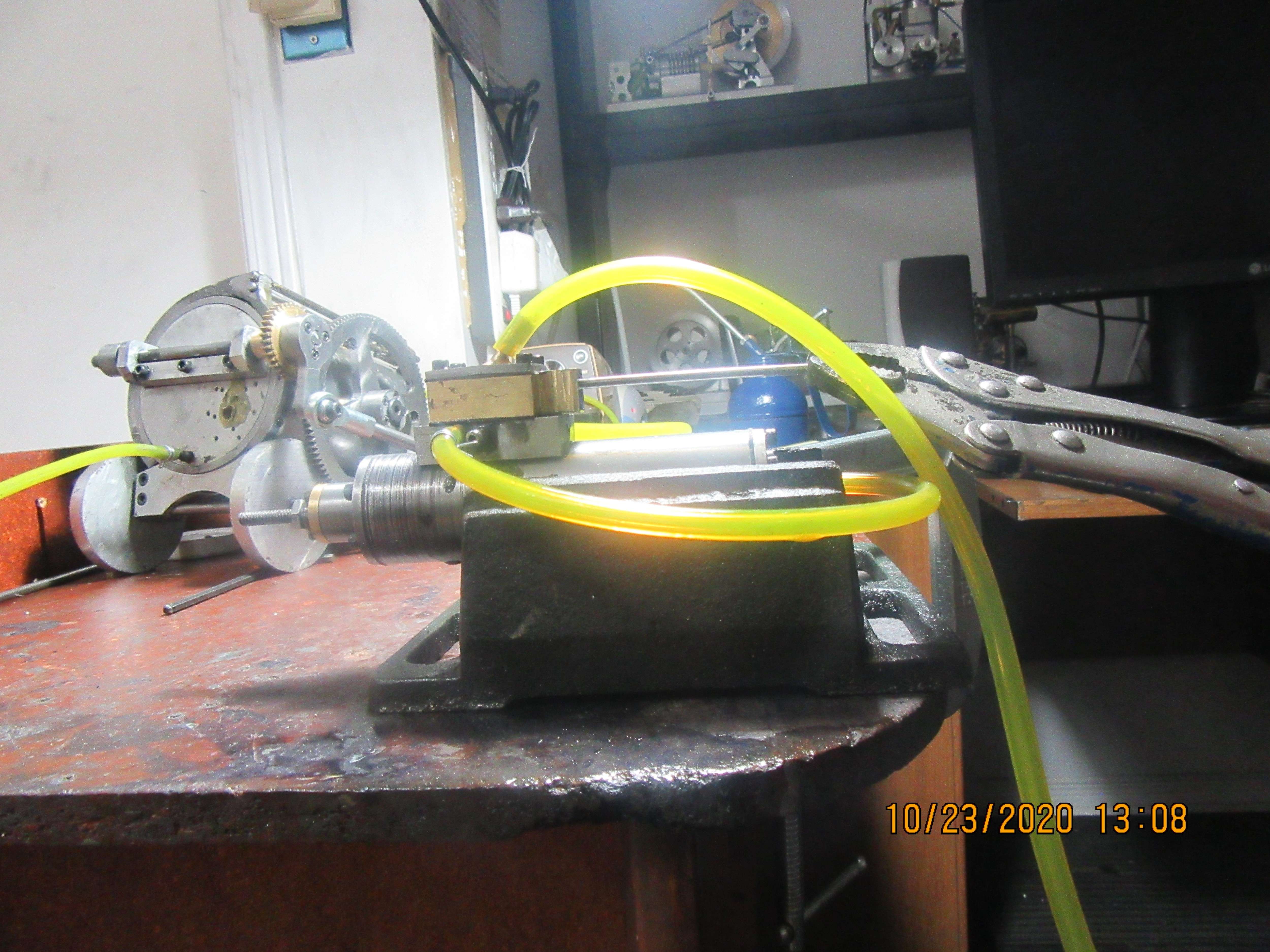
Building the Trevithick engine

Home Model Engine Machinist Forum

Help Support Home Model Engine Machinist Forum:

This site may earn a commission from merchant affiliate links, including eBay, Amazon, and others.
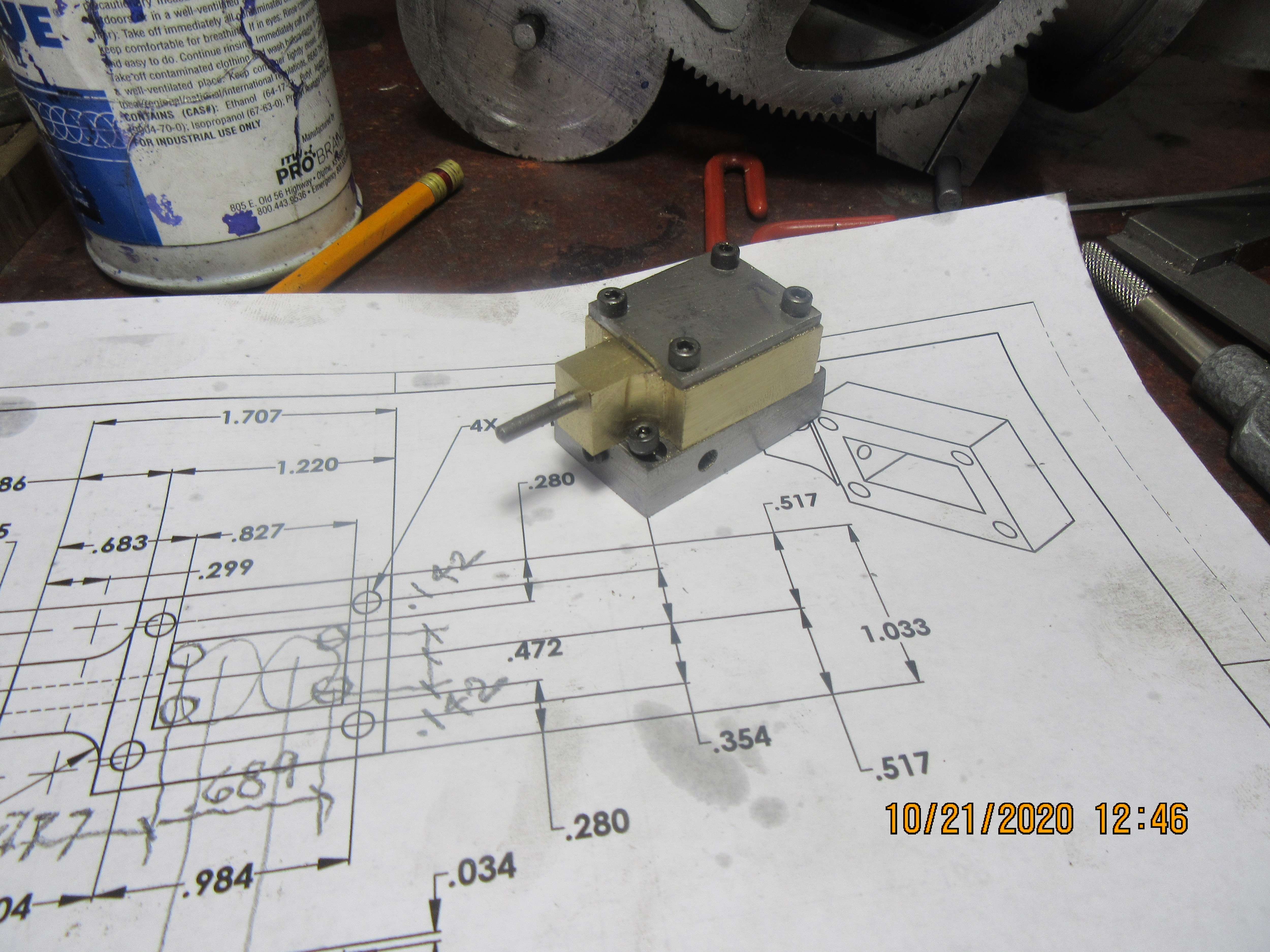
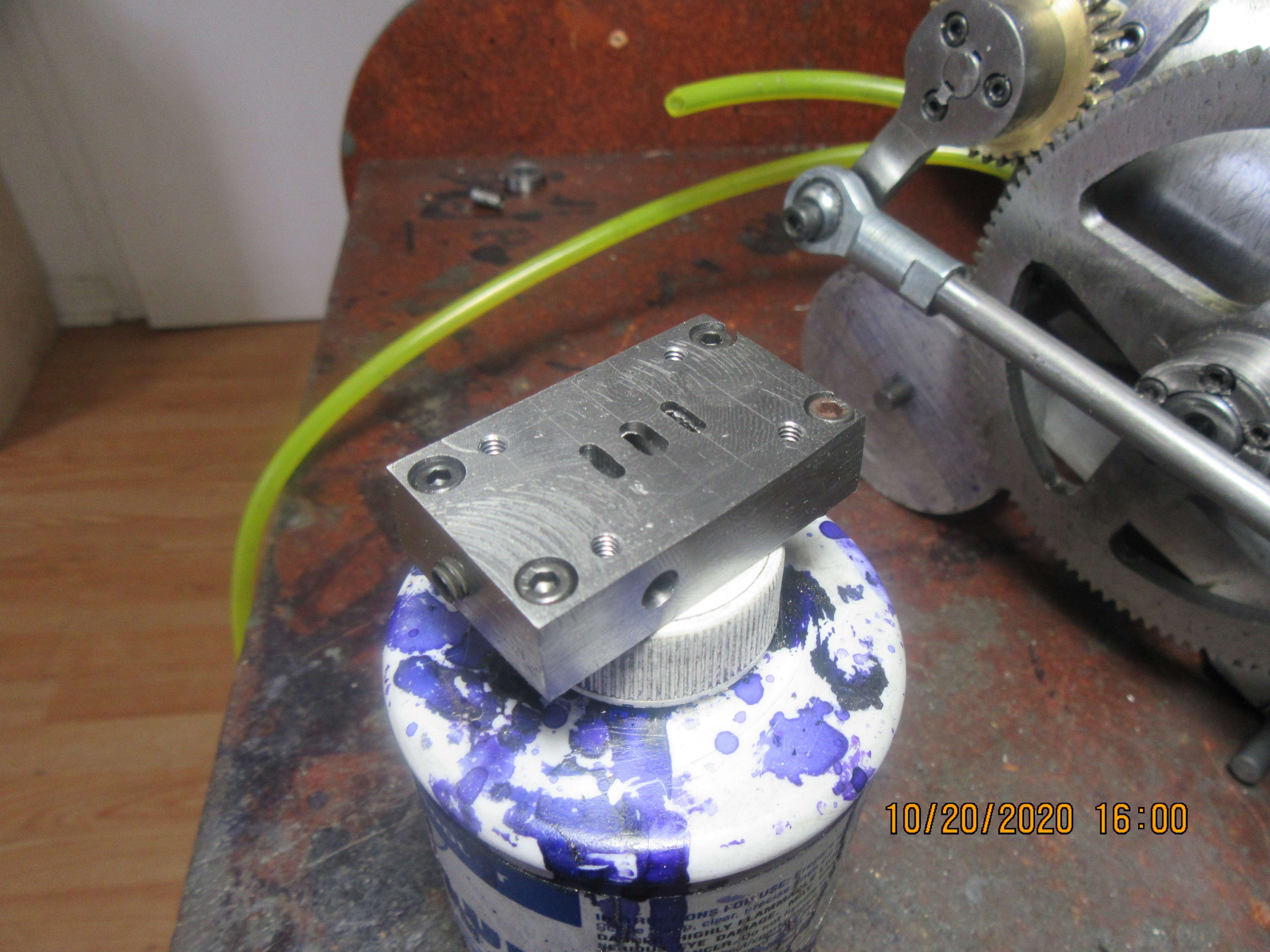
It feels like I must have been taking "slow pills" today. I managed to work all day and make only one part. This is the sub base for the new slider valve. The four shcs in the corners attach it to the cylinder. The four tapped holes are where the steam-chest bolt to it. The tapped holes in the ends are drilled galleries that needed to be plugged after the fact, so they were tapped and #10 set screws threaded in to act as plugs. There will be three tubes soldered into the block, two on one side and one on the other side. I still have some internal de-burring to do.
olhlxL.jpg
 
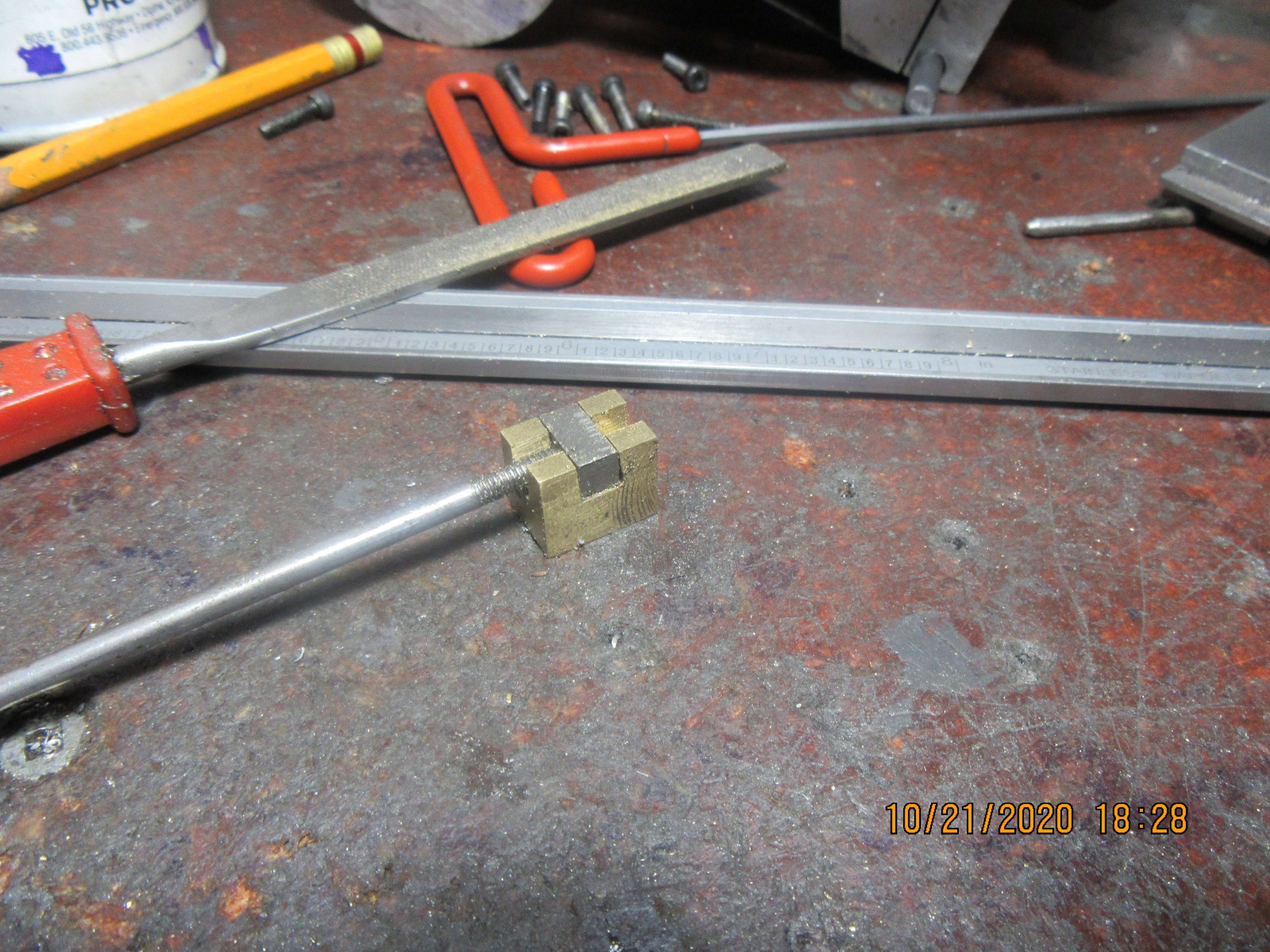
So far today, I've got a stem-chest and a steam-chest cover. I might have the internal slider by the end of the day. I'm anxious to see this controlling the cylinder.
FEUrWc.jpg
 
I did finish all of my slide valve business today. This is the slider, the nut, and the actuating rod. The brass steam-chest is not shown in this picture, because I managed to drill four holes in the wrong place. The holes are not in a critical area, and brass is about the same price as gold around here, so they have been filled with J.B. Weld and the steam-chest has been set aside to cure for 24 hours. Tomorrow I will make the eccentric and it's mount.
QDYdwB.jpg
 
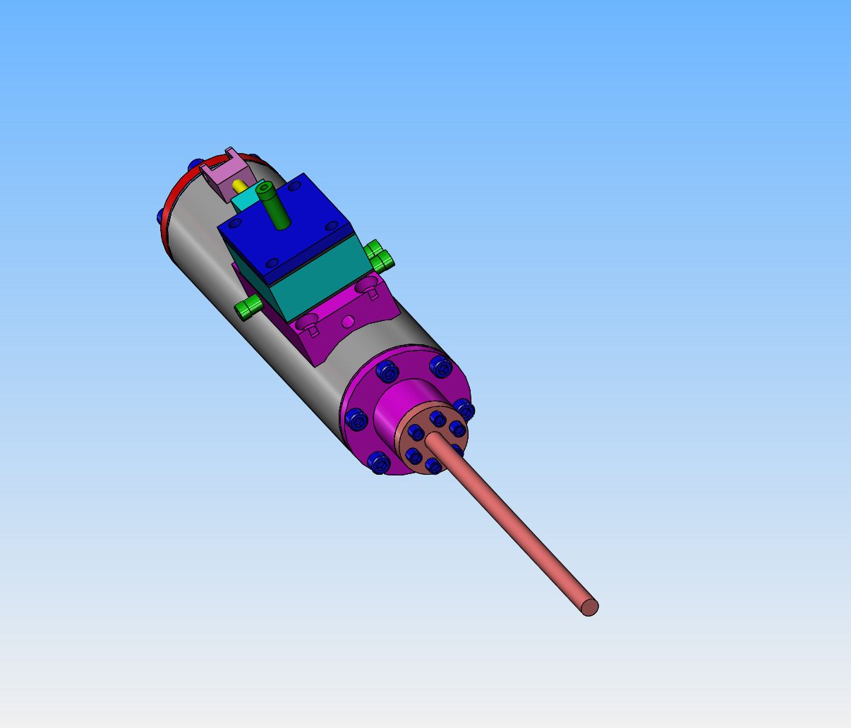
Last night I lay in bed reviewing what I had done yesterday, and came to the realization that I needed to get steam (air) into the new steam-chest. It already has 3 outlet tubes--One to go to the front of the cylinder, one to go to the rear of the cylinder, and one to go to exhaust. This morning I added an inlet tube to the steam-chest cover.
2rHWCs.jpg
 
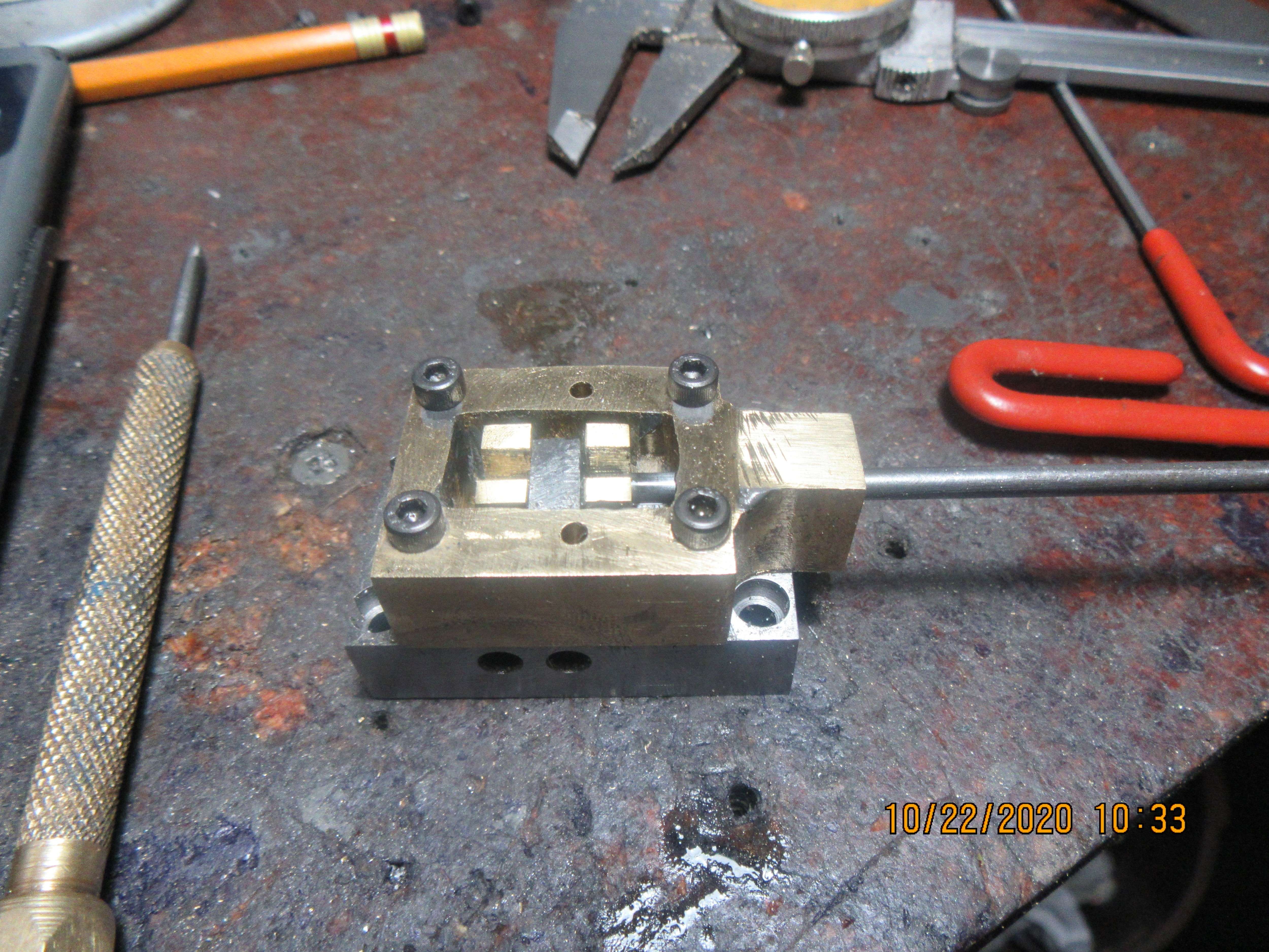
Okay, we are back up and headed for assembly. One trick I'd like to show. In the center of the brass steam chest you will see two .093" reamed holes. Dowels will fit thru them into 0.093" holes in the adapter plate below, (or it could be into a cylinder). They will not extend up beyond the top of the steam-chest. Why are they there?---Because, when you are setting these engines up to run, it is very important to know just where that slider is in regard to everything else. If you take off the steam-chest cover so you can see the slider, then it all falls apart in your hands and you lose all track of where the slider was in reference to the steam chest. With these dowels in place (loctited into the adapter plate or cylinder) you can remove the steam-chest cover plate and the steam-chest remains in place, so that you can see where the slider is in regard to the steam-chest.
uNvfb2.jpg
 
Today we have something to show. I have removed the 4 way valve which I copied from Trevithick's original engine ( I couldn't get the engine to work with that valve on it), and replaced it with a more conventional slide valve which will be driven by an eccentric cam on a countershaft, which is driven at 1:1 ratio by the crankshaft. The attached video shows the operation of the cylinder when I manually move the slide valve control rod with a pair of pliers. This is very encouraging, and I will now move on to the countershaft and eccentric which attach to the engine end-plate right below the crankshaft. The air hissing noise you hear is due to the fact that I haven't lapped the face of the slider to the steel adapter plate it slides on yet. Sometimes you get lucky and don't have to do that, other times you do.
eqvZpe.jpg

 
Last edited:
The way that the 1/8" control rod attaches to the brass slider is somewhat complex. The rod is threaded into a rectangular "nut" that "floats" inside the towers on the back side of the slider. It has to be a tight enough fit that the nut doesn't rattle around, but loose enough that it doesn't bind on the slider. If it does bind at all, it may be enough to keep the face of the brass slider from making a perfect seal against the steel face with the ports milled into it. This can be one cause of air escaping past the slider. That is easily corrected by a little creative file work on the nut or the slider.---or---It could be passing air because the face of the slider wasn't lapped against the steel. I find that I don't generally have to lap the faces, and if it is only a very small air leak, then running for half an hour will generally correct any differences in the faces. That video was made about five minutes after I had first assembled things and they were operating okay. I will do a bit of detective work tomorrow and see what is causing the air leak.---Brian
 
Brian, I like you attitude if that don't work go at if different, you kinda like a Duck, if he can't walk, he will swim and if that don't work he will fly but going to get there, gosh if that stumped you us who know less are never going to be there, thanks for you videos also, Joe
 
Thanks for stopping by and saying Hi guys. All of the new stuff I needed has been machined. I just pulled the end plate off the engine and plugged 3 holes that were not going to be used with my new crankshaft mounts. Tomorrow will be an "assembly day" while it all goes back together.---Brian
 
Today I completely disassembled the slide valve on the cylinder, and lapped both mating surfaces on a sheet of glass, beginning with 400 grit and finishing with 600 grit. It worked !! I have never had to do that before on any of my engines. It's one of the ten thousand things I know about but haven't actually done before. The air leak is gone---or at least so gone that it is no longer audible.---Brian
 
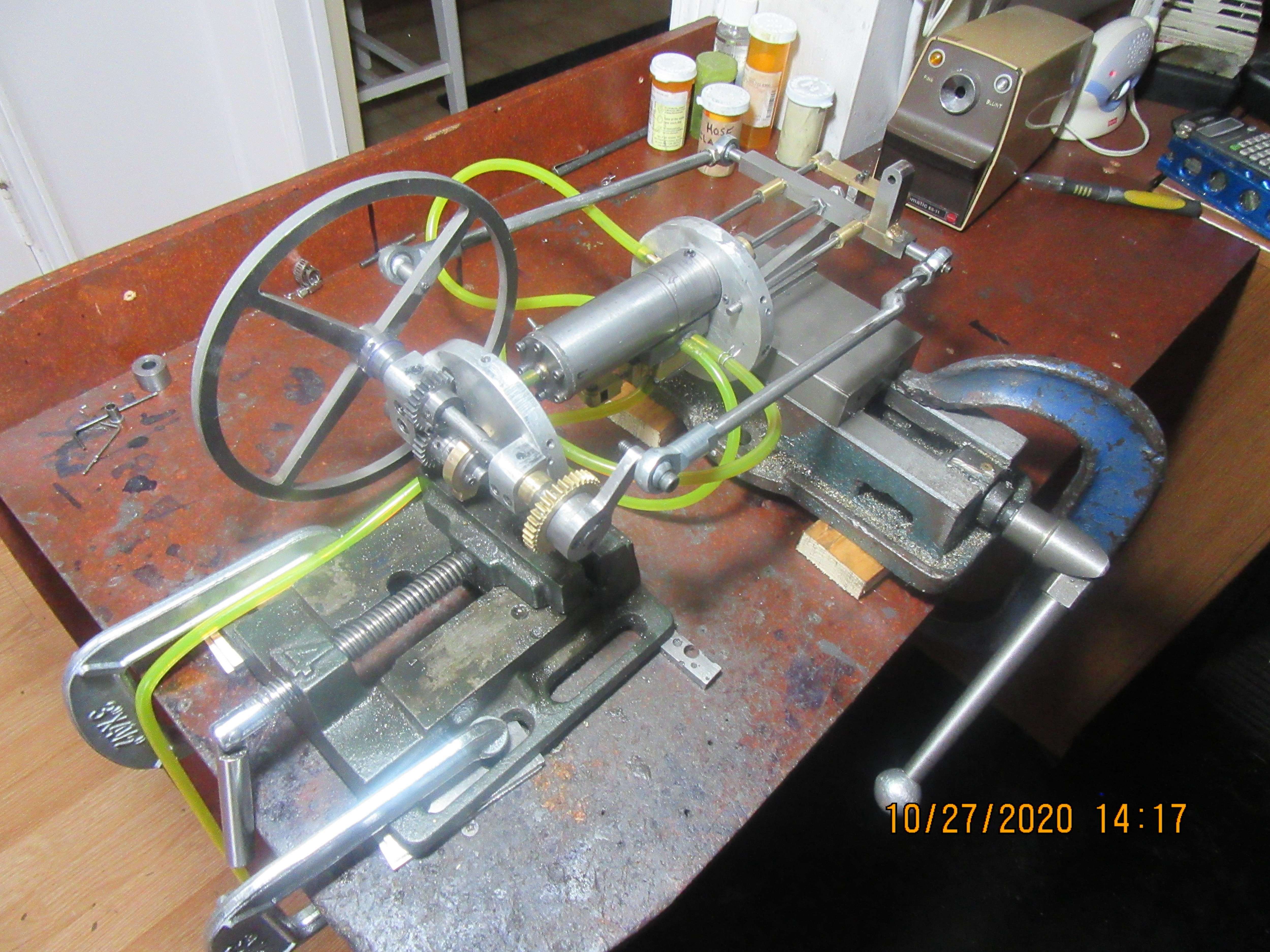
You don't have to be crazy to work here---but it helps!! Actually, what you see here is setting up the motor to run without the boiler. Since I can't get at any of the valve linkage when it is all inside the boiler, I will set everything up here and make all the adjustments required, then tear it down and reassemble it inside the boiler. --Sorta kinda like building a ship in a bottle.
eYcxS4.jpg
 
All things cometh to he who waiteth---If he worketh like Hell while he waiteth!!! This is the Rupnow-Trevithick engine on it's very first run with the new slide valve. The 1 1/4" square aluminum bar and the two vices are there just to hold the end-plates securely so that I can run the engine without the boiler in place in order to make adjustments. I think my waterjet cut flywheel is too light, but I can alter that. It is very gratifying to me to see this engine run for the first time.----Brian
 
I've been waiting for that - cool. Thanks for posting.
All things cometh to he who waiteth---If he worketh like Hell while he waiteth!!
Droll but true.
Regards, Ken
 
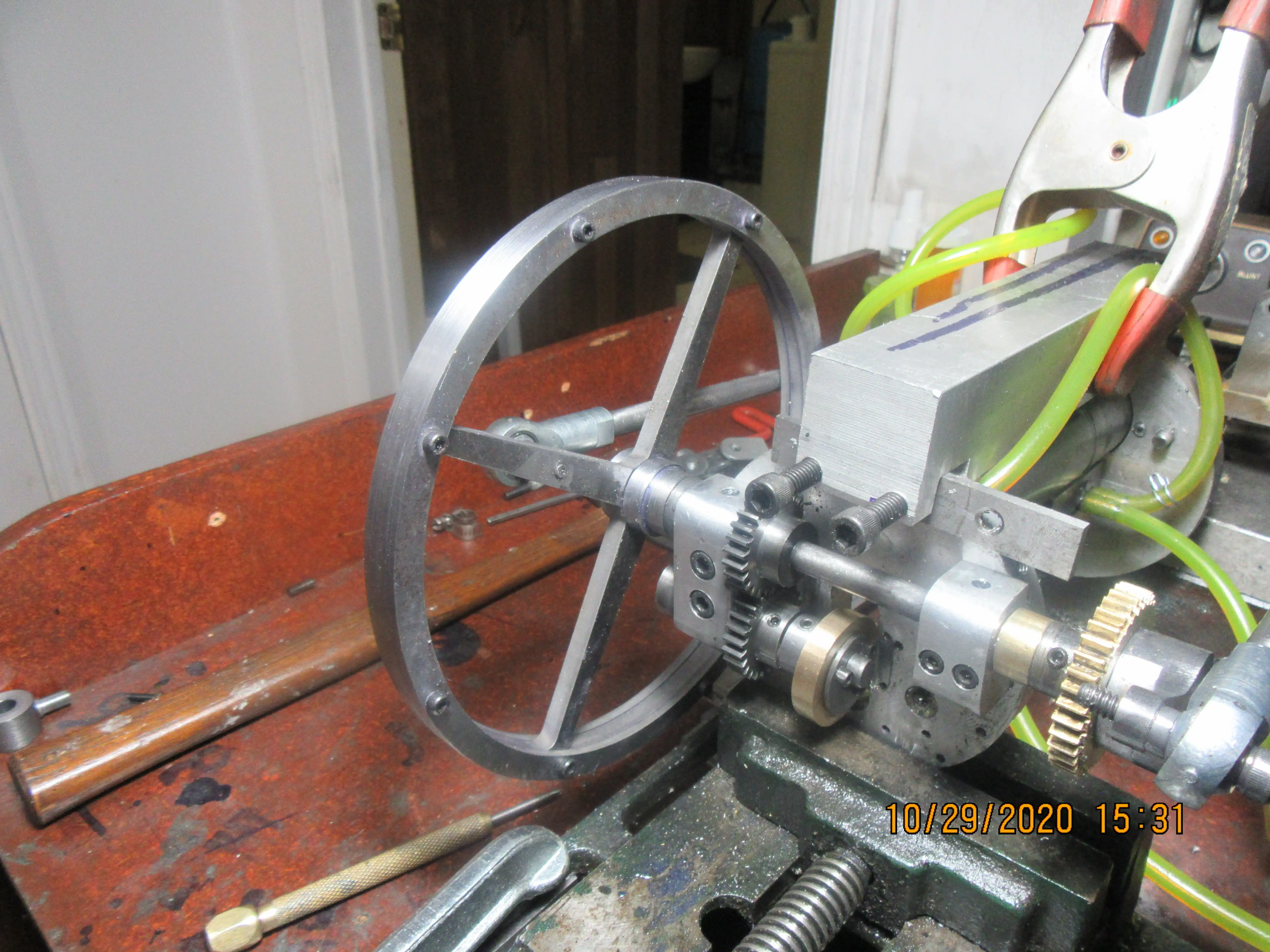
Todays game plan got changed a bit. My waterjet guy was able to make my two steel rings yesterday afternoon, so today I drove over and got them, brought them home, drilled and tapped them and mounted them to the existing flywheel. It's been a cold dreary, rainy day here, but I was glad to get out of the house for a while. The flywheel was originally a piece of 3/16" mild steel plate. I have added a 1/8" steel plate to each side of the rim to make it a little heavier, in hopes that this will let me run the engine slower.
0ikNZQ.jpg
 

Latest posts

Back
Top