Valve Gear Design for Steam Engines - My approach

Home Model Engine Machinist Forum

Help Support Home Model Engine Machinist Forum:

This site may earn a commission from merchant affiliate links, including eBay, Amazon, and others.
Green Twin: Please stop me as soon as you think I am drifting away from the intent of your thread. My comments are usually in response to something I think may be not right, so to open the debate "fills the gaps" in my knowledge - and perhaps other readers' knowledge. Either that or to expound on a parallel or related matter that may broaden the subject. But I can drift away from the main thread so need whipping back into line!
Thanks for your patience.
K2
No problem, I am like a sponge; I read and absorb anything and everything that gets posted.
The more I read, the more I learn.
The more I learn, the more things I can do.

I enjoy reading what others post as much or more as I do my creating own posts/threads.

You will never hear me complain about drifting off-topic.
I enjoy topics wherever they go, whatever knowledge they cover.

Its all about learning for me, and I am basically interested in anything and everything, but especially anything technical-related.

.
 
Steamchick - I take it your post no 37 was meant to be just a quick trot over some of the history (as it would take me quite some time to go through the detail misunderstandings I noticed).

(Off topic: I don't know about rack and pinion railways. Their practice may well differ from normal. I volunteer at a heritage railway and can assure you the normal way of reducing speed with an adhesion system is to use the brakes! The locomotive provides a vacuum for the train brakes, and may itself have vacuum or steam brakes. Alternatively, air brakes are used. Air brakes are required for running steam excursions on Network Rail.)
 
The Brits used compressed air for locomotive brakes, and Westinghouse came up with the vacuum air brake system ? so that loss of pressure would automatically stop the train?
Check me on that.

I distinctly recall riding a steam train when I was young, and wondering what the device was on the front of the locomotive.
It was puzzling because the device was running like a beaver, making a lot of noise, even though the train was not moving, so I could not figure out at the time exactly what that device was doing.


Westinghouse-252-253.jpg
Westinghouse-2429.jpg
Westinghouse-2436.jpg
Westinghouse-2450.jpg


Last edited:
Hi Charles. Yes. Just musing on the history, but as you recognise, I'm not exactly correct - but that's about what I know of the development of valve gear! I'll be glad to hear the corrections - as will others, no doubt.
But my aim was to say that valve gear wasn't highly refined until well after railways started using locomotives. The earliest I could find a D-valve was James Watt's early 1830s, around the time railways were just taking off.
Do you know the earliest D-valve adoption?
K2
 
This is one of the better illustrated old books on steam engines.

It is shocking how complex the old steam engines became over 100 (+) years of evolution.
The very best minds in academia devoted entire lifetimes to studying them, and writing books about them.

Steam engine design ruled supreme for many years.

The mathematics behind the steam engines was also very complex, and the old books are often full of calculus.

https://archive.org/details/steamengineprinc00crofrich/page/12/mode/2up
 
I actually found a paragraph in one of the old books I was browsing, and have promptly lost it again.
It mentioned someone who patented a D-style valve in the late 1700's.

The original steam and exhaust valves were typically located at the ends of the steam cylinder.
The early D-valves were very very long, and the ends of the valve uncovered ports near the end of the cylinder, with a slight recess along the underside of the valve.

Apparently the D-valve evolved into something shorter, and the passages were stretched out from the ends of the cylinders to a central point under the steam chest.

.
 
Last edited:
Do you know the earliest D-valve adoption?

Murdoch patented the 'long' D slide valve in 1799. Mathew Murray's 'short' slide valve patent of 1802 was for the slide valve we recognise.

Can I suggest some reading:
The Steam Engine of Thomas Newcomen - Tom Rolt
Richard Trevithick - Dickinson & Titley
Valves and Valve Gear Mechanisms - Dalby
Heat Engines - (eg) Ripper or Low
The Efficient Use of Steam - Lyle
 
Last edited:
Thanks GT.
I Have a small library of my Father's and 2 Grandfathers' books, as well as a half dozen I acquired myself "with an idea of studying them all" - someday...
One of the oldest is a Victorian book on Chess, and another Maxwell's book on Electromagnetic theory - from only a decade or so after the first re-print! - That one is still used as a college text book, so they were clever folk back then! But most are on Steam engine stuff as they were all into Steam engine careers - on ships and power stations, etc. so had to study it all in their youth. I had the pleasure of studying Quantum mechanics, etc. - and left my brain somewhere I can't find... like Shroedinger's cat?
Kust searched the "Internet archive" for D-Valve: 1,900 odd entries found - then it crashed and stopped the page from working. - Oldest date I spotted (before t crashed) was 1915... presumably because most wasn't dated.
Keep on writing, I am enjoying your explanations.
K2
 
Thanks Charles.
I'll have to read some of the stuff I have before I buy more books. I'll admit to not being a proper student of all this, just a "casual interferer" - with lots of (distorted?) memories from my Father and his friends, colleagues and family (Uncles and Grandfather) all discussing engines at great length... Steam, Diesel, Petrol, etc.
With ancestors who worked at Wylam and Ryton pits as Engine drivers (Water pumping) at the time George Stephenson and father worked there, later at Stephenson's works, and driving locos on the Stockton and Darlington railway from ~1826 for a number of years before travelling with Robert Stephenson's gang "building railways" to London and Swindon and up the line to Wales and Liverpool, I have some heritage that has been lost with time. So I know nowt!
But am glad to have met the experts on this site!
K2
 
Green Twin,
Terrific thread. Really enjoyed the explanation of the displacement curve and the beautiful engravings.

In an earlier post you said:
"It should be noted that a D-valve is not rigidly connected to the valve rod, to allow the D-valve to move in/out slightly, and move closer to the port face as wear occurs."

I am attempting to replicate a Muncaster Joy valve steam engine, and was contemplating the D-valve design. One member chose to deviate from the Muncaster drawing and make a D-valve similar to what I have seen Stuart Models use and inline with your comment. It would allow floating and compensate for wear as you described. Another builder criticized this as the adjustment wasn't as infinite or as precise.

Please note the valve ports of the scale model I am building are only 0.118 inch for admission and 0.283 inch for exhaust. What would you recommend?
I believe Kirk's design to be the best


Muncaster's Kirk's
Muncaster D valve.png
Kirks D valve.png
 
The Brits used compressed air for locomotive brakes, and Westinghouse came up with the vacuum air brake system ? so that loss of pressure would automatically stop the train?
Check me on that.

I distinctly recall riding a steam train when I was young, and wondering what the device was on the front of the locomotive.
It was puzzling because the device was running like a beaver, making a lot of noise, even though the train was not moving, so I could not figure out at the time exactly what that device was doing.


View attachment 140392View attachment 140393View attachment 140394View attachment 140395


That is the Duplex pump running on a Shay steam engine in Cass WV. USA.
 
I can only state my preferences for typical steam engines that I reverse engineer and sometimes build.

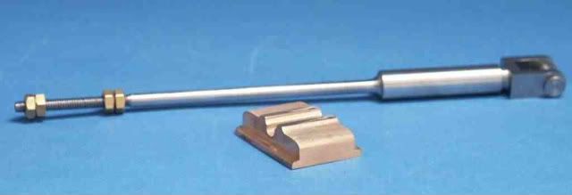
I have seen D-valves with a yoke around them, but more commonly I see simple steam engines with a D-vavle that has a slot in the top, and the valve rod goes through the slot or oblong hole, with a nut on either side, but a sliding fit between the valve and the nuts.

I prefer the slot in the top of the D-valve, or perhaps a balanced D-vavle with a slot.

There are the valves in Dave Richard's O&S (with a sleeve on the valve rod), and the valve in my O&S (which I think incorrectly does not have a sleeve).
I think Dave's engine has been rebuilt correctly, and the sleeve would be a sliding fit in the slot.

So this is my preference, but in the modeling world, I see a lot of freelance designs, and there is no problem with that approach, but I prefer to copy some version of some old design, as opposed to freelancing a design as my dad always did.

Image12 (2).jpg
r20190220_130440.jpg
 
Here is a hoist engine valve, also the typical D-valve with slot in the top.

Its a simple elegant solution for a simple elegant little engine.

I do intend to use a balanced D-valve though, which was sometimes used back in the day.


No-29a.jpg
 
I can't see a sleeve on the Kirk drawing, just nuts which would make it hard to set the position as the single nuts could come loose. You either want a sleeve between the two nuts so they can be done up tight against it or you want nuts and locknuts either side. Either way you need to be able to swing a spanner and the nuts should not clamp down against the valve as it still needs to move off the port face to prevent a hydraulic lock if condensate builds up in the cylinder

My Fowler Traction engine has the lock nutted option and is true to what the full size also had. I think the rest of the steam engines with slide valves all have the slot and rectangular nut.

Valverod.jpg
 
Back
Top