Stephenson's Rocket--Working Model

Home Model Engine Machinist Forum

Help Support Home Model Engine Machinist Forum:

This site may earn a commission from merchant affiliate links, including eBay, Amazon, and others.
Hi Folks,

Over the years I've noticed the angle of the cylinders appears to be at about 30 degrees to horizontal. The cylinders are quite a bit lower in angle on the original as shown at the Science Museum in London.

https://collection.sciencemuseumgroup.org.uk/objects/co8084947/stephensons-rocket-steam-locomotive
It's a neat model either way, but I was wondering if the folks who put the pieces of the original together just got it wrong, or if all the replicas thereafter have it "wrong". Could be Rev 1.1 of the engine increased the angle and all the versions built after the competition used the higher angle. I've never found a definitive answer, probably looking in the wrong places. Anyone know?
 
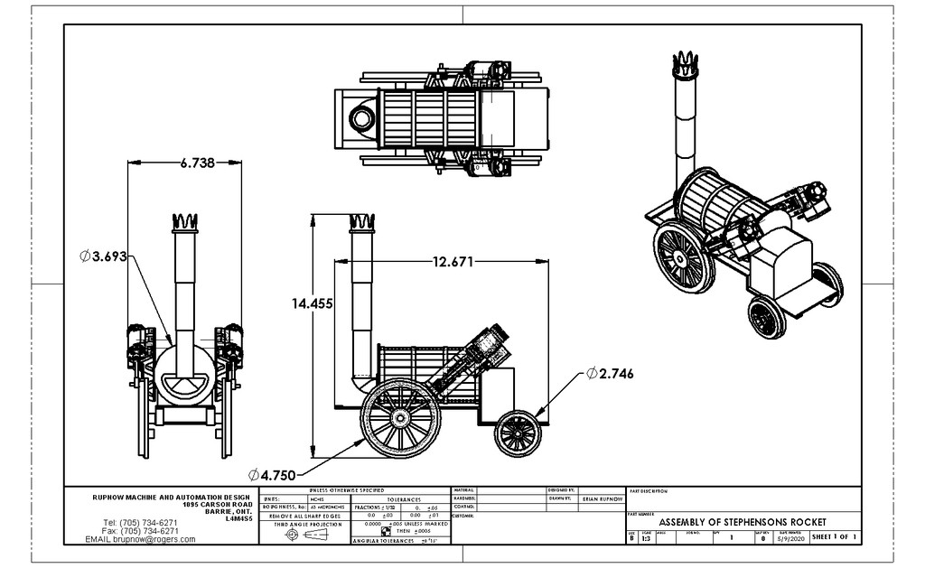
The Stephenson's Rocket went thru many design changes and updates after it first ran. You can find info about 4 or even 5 different configurations of it, and they are all right. My cylinders are 41.5 degrees off horizontal.---Brian
 
Greetings again,

Sorry for the follow up, but I just found this. According to the Scientific American supplement:

http://www.gutenberg.org/files/11734/11734-h/11734-h.htm#3
The lower cylinder angle was, along with almost everything else, a change after the competition, and the ubiquitous steeper angle cylinder and wooden barrel tender are consistent with the very first Rocket as used to compete, just the production models were very different a year later... All these years I'd wondered why the Science Museum display was so different, it seems that they display what was perhaps the first production model as found in 1830, but use the 1829 date.

Best to all, stay healthy!
Stan
 
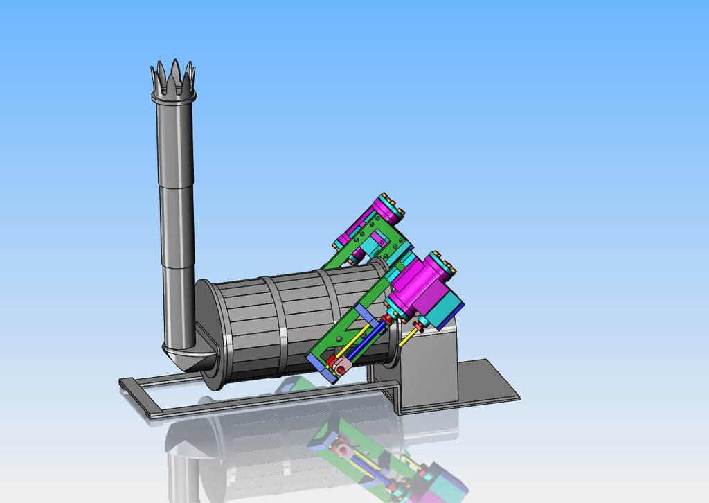
This morning I designed the "opposite hand" engine and base, and about half of the simplified body. This afternoon I will probably finish the body design. My main interest of course is the engines.
7cYb50.jpg
 
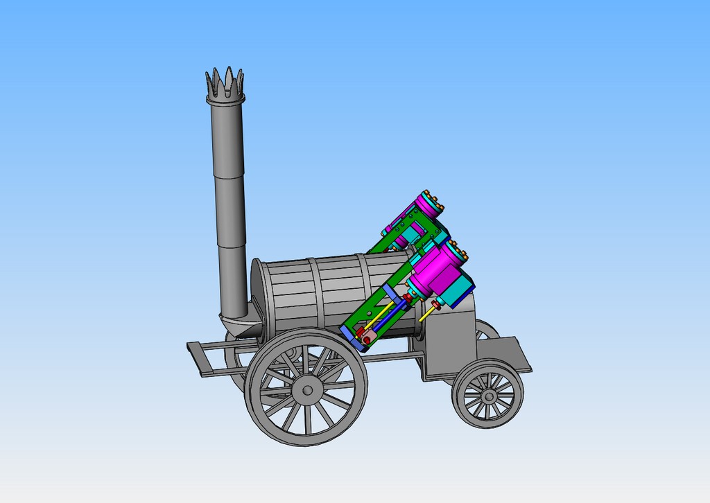
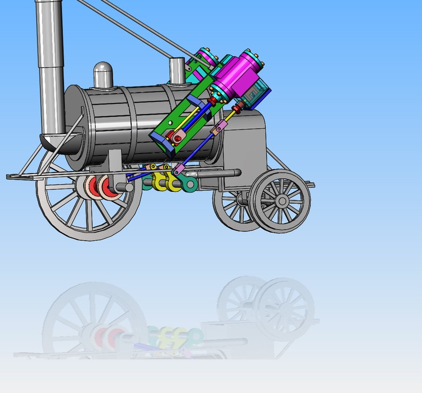
That's enough fun for today. Even though I have "super simplified" the body, there is still a lot of pieces to it. I have to add some axles and stay rods yet.
rrktl0.jpg

reD0nu.jpg
 
Last edited:
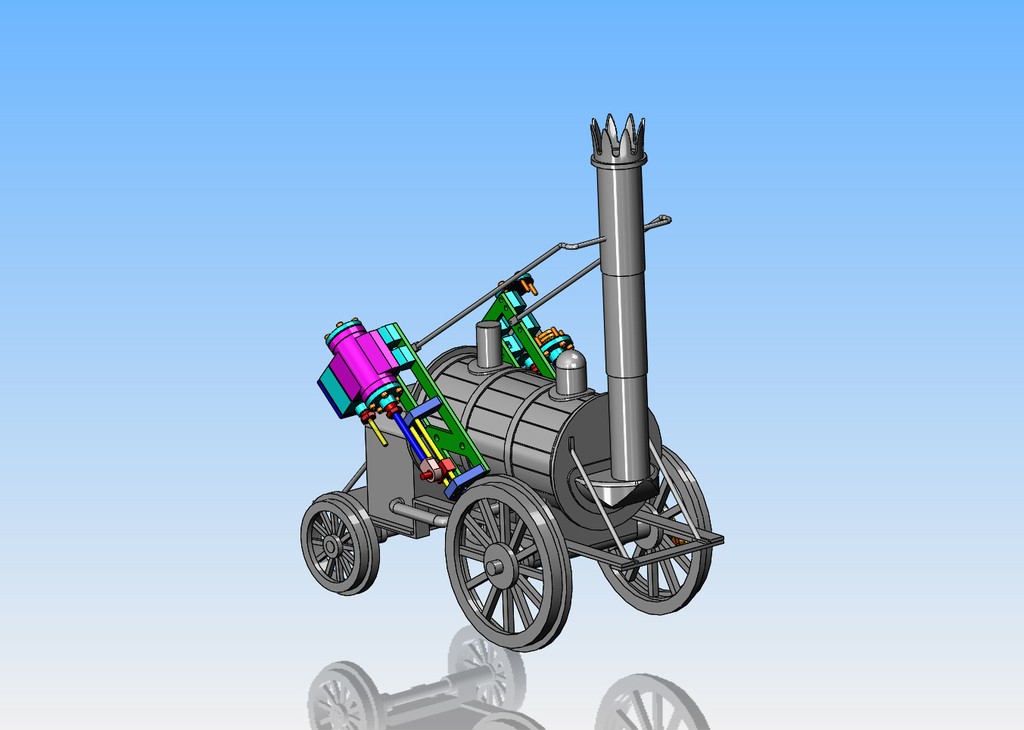
So that's it. The model of the Stephenson's Rocket is greatly simplified from the original steam driven unit, but it certainly looks enough like the original that it won't be mistaken for anything else. Even in it's very simplified form it still represents an awesome amount of work. This has provided me with some nice design time, and the engine packages should be a lot of fun to make.
Vyr0Vj.jpg
 
Hi Guys,

There is a full size replica of the Rocket built from the original plans located in the Railway Museum at York. I believe it was in steam not too long ago. Unfortunately I missed that event.
 
It’s all my fault. I put away the snow shovels. Had to dig them out again. Man that was wet heavy snow. Many very unhappy birds. No gardening this week.
 
You might want to look at the LBSC design for "Rainhill" which is a similar engine, or "Canterbury Lamb". Those are both of LBSC's versions of the "Rocket" I know you mention the model just being a shelf display, but once you see them, you might want to just build one anyway, and then put it on the shelf. For one thing, all the castings are available through GLR Kennions, along with the drawings. It would be a very inexpensive model locomotive to build.
I am in the middle of one now. They have been very popular, and have excellent reputations as "good runners" even as small as they are.
 
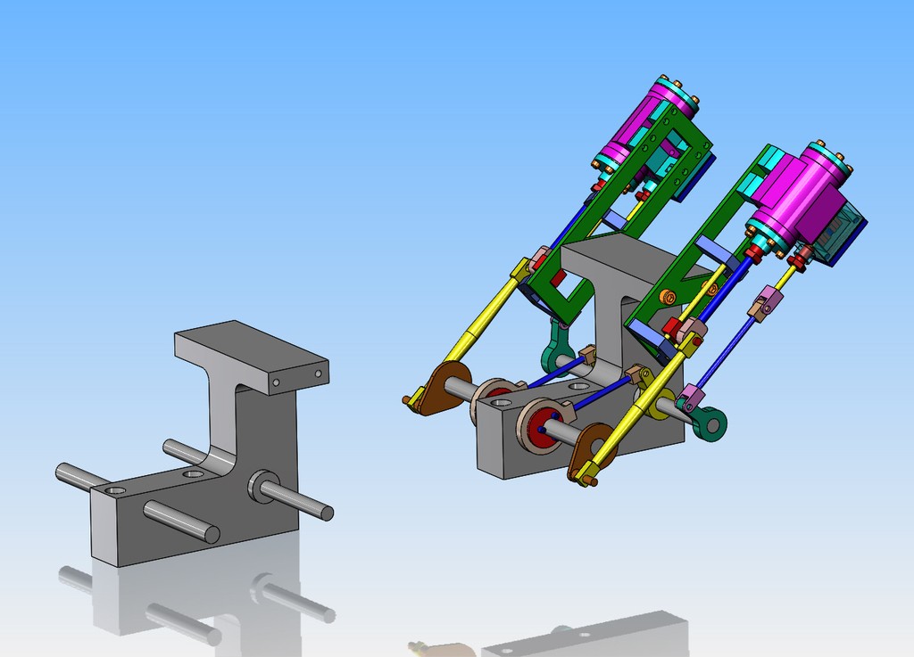
George asked me yesterday how I was going to operate the steam valve. I had it in my head but it took most of today to design it and lay it out. The eccentrics mounted on the drive axle operate levers attached to an intermediate cross shaft, which is supported below the boiler. That shaft has a second set of levers on it which connect to the linkage running up to the steam-chest. Again, this model will not have the sophisticated hand controls that the original Rocket had. I have removed the near side drive wheel in his model, so you can see what my plan is for operating the valve operating mechanisms. Note that I have not shown the support for the intermediate shaft in this model.
OiQu73.jpg
 
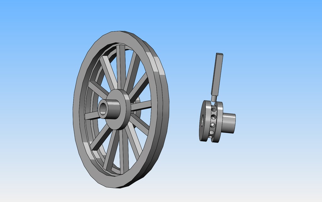
Other than the engine assemblies, this model is relatively simple. Mostly straightforward milling and turning---but---The wheels are going to be monsters. Since I won't be running my engine on a track, the wheels can be mostly made from aluminum---I think. Very much of the "character" of this model is the wheels with square spokes. There is no easy way to make these wheels. They are going to have to be "built up" from components---an inner hub, an outer rim, and individual spokes. For the scale I am working with, 3/16" square spokes look about right. I've thought about this a fair bit, and this is my plan--so far. I know that I can buy 3/16" square steel keystock. (Not sure if I can get 3/16" square aluminum or not). If I cut all of the spokes to an exact length, and make a proper jig to hold them, I can turn one end of the spokes to be round. I can lathe turn the inner hub and using my rotary table on the mill, I can drill 12 blind 5/32" diameter holes equally spaced in the hub. I can turn the hub as shown, so that when the spokes are installed they have to all fit into the groove, which will keep them all parallel with the face of the wheel. I'm thinking that would be a Loctite job. It would be a wonderful thing if, when assembled, the outer ends of the spoke array would be perfectly concentric with the center of the hub, but in the real world that doesn't happen. Thus, the design of the outer rim which is most visible will have a "lip" that extends down over the end of the spokes to hide them. That way, I can design the outer end of the spokes to be about 0.010" short of contacting the inner rim surface, but they will rest against the lip. At his point I see a simple jig to maintain concentricity between the outer rim and the inner hub. IF I use steel keystock for the spokes, and a steel outer rim, then I can use my tig welder to attach the spokes to the outer rim and it won't show. I don't have the proper gas bottle to weld aluminum, and I have no experience with welding aluminum, but with steel spokes and rim, I could manage.
nL5osv.jpg
 
This valve gear layout on the Northumbrian is almost exactly what I will use on the Rocket . The Norhtumbrian has a third eccentric in the center that drives a pump or something, the Rocket won't have that one.
 
Due to the fact that there will be a lot of work in the model of the Rocket, I will first build the engines and bases and mount them to a Test Stand. The test stand will mimic all of the attachment points and axle positions that will be on the finished Rocket model, but will be a lot less work. After I have ran the engines to my satisfaction in the test jig, I will go ahead with the actual model of the Rocket.
mzlvm5.jpg
 
I don't have the proper gas bottle to weld aluminum, and I have no experience with welding aluminum, but with steel spokes and rim, I could manage.

Brian, though you can use helium or a helium-argon mix for welding aluminum, you can also use straight argon, same as for steel. As I understand it, helium in the mix will increase the heat & penetration, but decrease the cleaning action, so generally only used for welding thicker aluminum.

To weld aluminum, key #1 will be having AC capability - whereas steel is welded using DC, aluminum needs AC to clean the oxide layer.* Key #2 is the right type of electrode - if I recall correctly, you mentioned having thoriated tungsten electrodes, which are the "classic" choice for DC / steel, but not suitable for AC. The classic choice for AC / aluminum is pure tungsten. But there is a better choice: 2% lanthanated tungstens - they handle the AC better than pure tungsten, AND can handle DC equally well - one tungsten to rule them all! Key #3 is the experience factor - TIG welding aluminum is definitely harder than TIG welding steel, or at least I have found it so. I generally feel able to tackle most anything in steel, but I don't yet feel like I have even minimum competence with aluminum.

*Okay, supposedly you CAN weld aluminum using DC, or so I have read. The problem is you have to use DCEP, which puts 70% of the heat into the torch - so you have to use a lot of amps, a big electrode, and really need a water-cooled torch. I did try a time or two when I had a DC-only machine, but couldn't even get close to managing it with my air-cooled 200 amp rig. As I recall, helium in the mix may also be part of the equation for successfully welding it using DC. But for us average home shop folks, AC and argon are the way to go.

Here's a useful FAQ: Aluminum Welding FAQs | Lincoln Electric
 
Hi Folks,

Over the years I've noticed the angle of the cylinders appears to be at about 30 degrees to horizontal. The cylinders are quite a bit lower in angle on the original as shown at the Science Museum in London.

https://collection.sciencemuseumgroup.org.uk/objects/co8084947/stephensons-rocket-steam-locomotive
It's a neat model either way, but I was wondering if the folks who put the pieces of the original together just got it wrong, or if all the replicas thereafter have it "wrong". Could be Rev 1.1 of the engine increased the angle and all the versions built after the competition used the higher angle. I've never found a definitive answer, probably looking in the wrong places. Anyone know?
Hi Guys,

There is a full size replica of the Rocket built from the original plans located in the Railway Museum at York. I believe it was in steam not too long ago. Unfortunately I missed that event.
Actually there are three rockets, a sectioned one to show its internal workings, which is on permanent display at York NRM, and shows its advanced (revolutionary) tubular boiler design. Then there is the replica that runs and takes people on rides behind it on a short section of track, though from what I understand the boiler design is slightly different to meet todays regulations. Then there is of course the original, which competed in the Rainhill trials. The was recently on display at NRM in York as part of the fire and ice event around York. The Rocket as shown, is in its withdrawn state, there isn't ever going to be an attempt to restore it as it is significant as it stands, to restore it there would be so much history and knowledge lost. It is now quite a fragile old beast. its only moved occasionally, I believe it should be in London now or least was the plan it may still be York due to the lockdown. Rocket started with the steep angle of the cylinders, in an attempt to make sure the steam didn't condense in the pipes and cause hydrolock or loose its power. The cylinders where dropped to the angle you see on the original rocket to preserve the track from the hammer blows that come from the cylinders acting directly down towards the track. There were other "rockets" built by Stephenson, and then he got enthusiastic and did a 0-6-0 design, as so the evolution continued. Also Rocket was only ever yellow for the trials, the engine burned its chimney and boiler cladding paint to a dirty brown colour as the pigment wasn't up to such heat and broke down, the same with the yellow, it is reputed the engine looked quite a shabby affair when all was done at the trails, so rocket took on its livery of a deep green colour and black chimney, much like a GWR engine would be coloured but with less brass bits.

If there is anything specific that you'ld like to know I can field it to two of my friends, one the senior curator of the NRM, the other a historian of the railways, who's wrote several books on the subject of early railway development.

Jon
 
Apologies Brian but I was also thinking about as a scholar in Newcastle going into the Exhibition Park and into the museum where there was 'another' steam engine as well as Turbinia.

Sorry Brian but this is part of my heritage and George Stephenson 's cottage was only a mile or so where I was born and even less from wwhere my father worked.

I suspect but never got any sensible information as to whether my Grandfather, Sam Atkinson worked as a blacksmith for Timothy Hackworth.
 
An alternative to welding aluminium is a process known variously as 'Lumiweld', Technoweld' etc.
I've used it for a variety of applications, including modifications to a motorcycle gearbox cast casing and fabrication of a large primary drive case. Only a propane torch is required.
 
Due to the fact that there will be a lot of work in the model of the Rocket, I will first build the engines and bases and mount them to a Test Stand. The test stand will mimic all of the attachment points and axle positions that will be on the finished Rocket model, but will be a lot less work. After I have ran the engines to my satisfaction in the test jig, I will go ahead with the actual model of the Rocket.
mzlvm5.jpg
All the castings for LBSC's "Rainhill" or "Canterbury Lamb" will only set you back by $200. They are available from GLR Kennions in England. The reason LBSC didn't call either model "Rocket" was because he made some small changes to make it an operating locomotive, so therefore it was not a completely accurate model of "Rocket" He normally would use a similar but different name from the original engine if it was not an exact model, but where he kept the original name for the model, they are usually a close copy of the prototype. So, with LBSC, you can tell by the name whether it is a true scale model, or a simplified locomotive designed to actually run under steam.
 
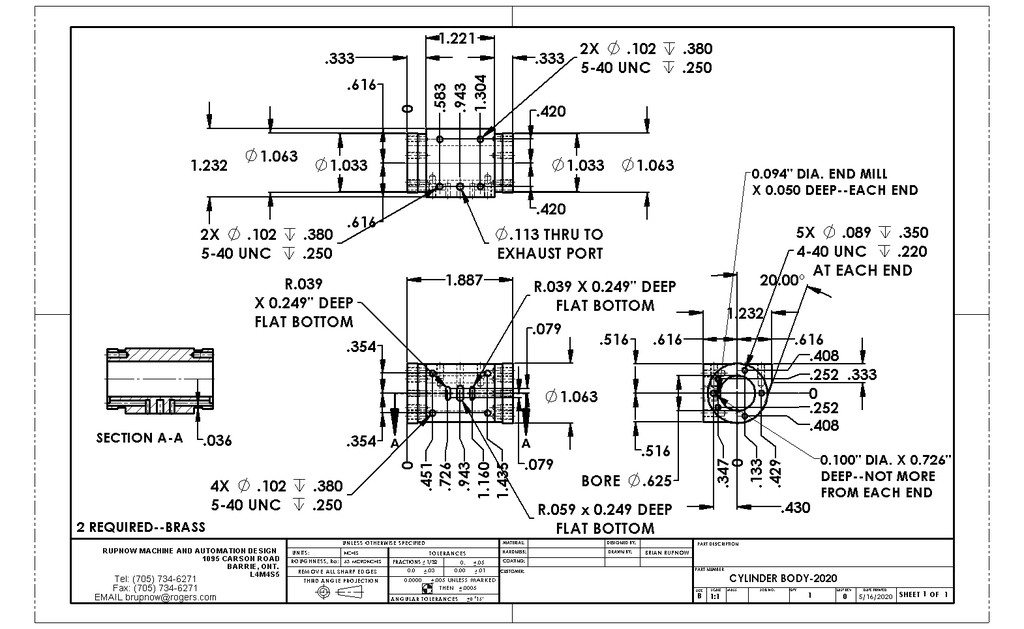
I'm getting close to making a start on the Stephenson's Rocket cylinders. I went to my metal suppliers this week and bought a 12" length of 1 1/4" square brass. This will give me enough material to make two cylinders and two steam chests.---and maybe 4 cylinder end caps but I'm not sure yet. There's going to be a bit of finagling, because this brass is 1 3/4" across the diagonals and the bore in my lathe spindle is only 1 1/2". I don't want to waste any of the brass, because that 12" length cost me $50. I will probably hold one end in my four jaw chuck and use a live center to support the outboard end. I can turn the outboard ends of both cylinders in one set up, but I can't bore the cylinders in the same set up, so I"ll have to think more about this.
xXiAuF.jpg
 
Back
Top