Stephenson's Rocket--Working Model

Home Model Engine Machinist Forum

Help Support Home Model Engine Machinist Forum:

This site may earn a commission from merchant affiliate links, including eBay, Amazon, and others.
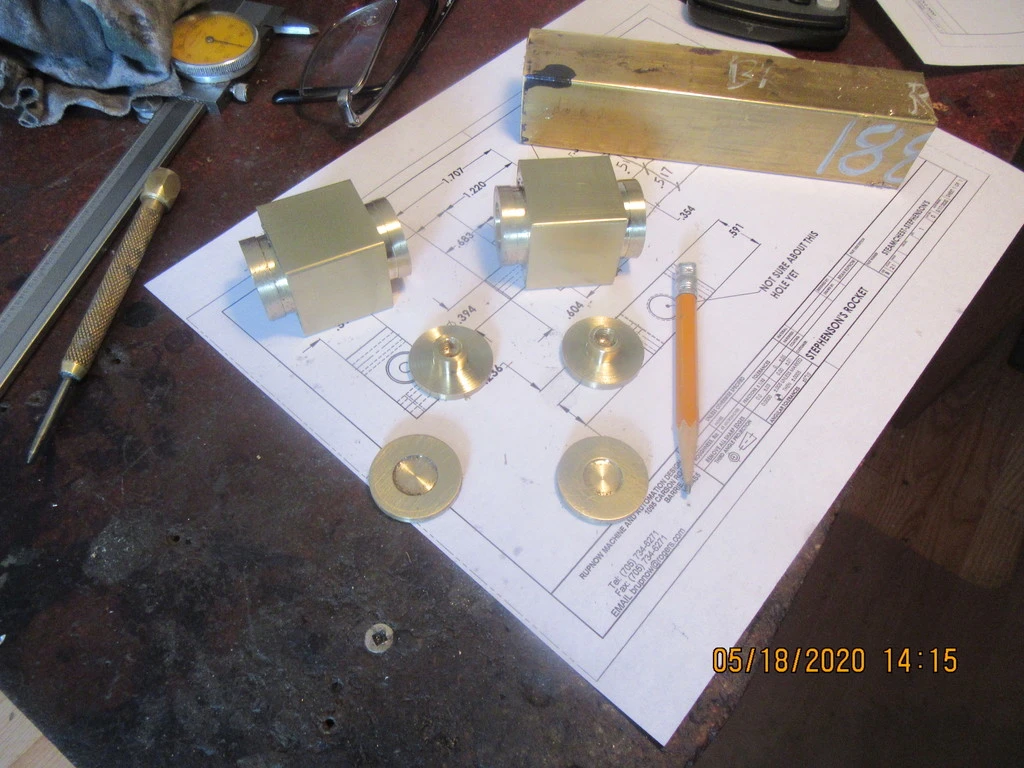
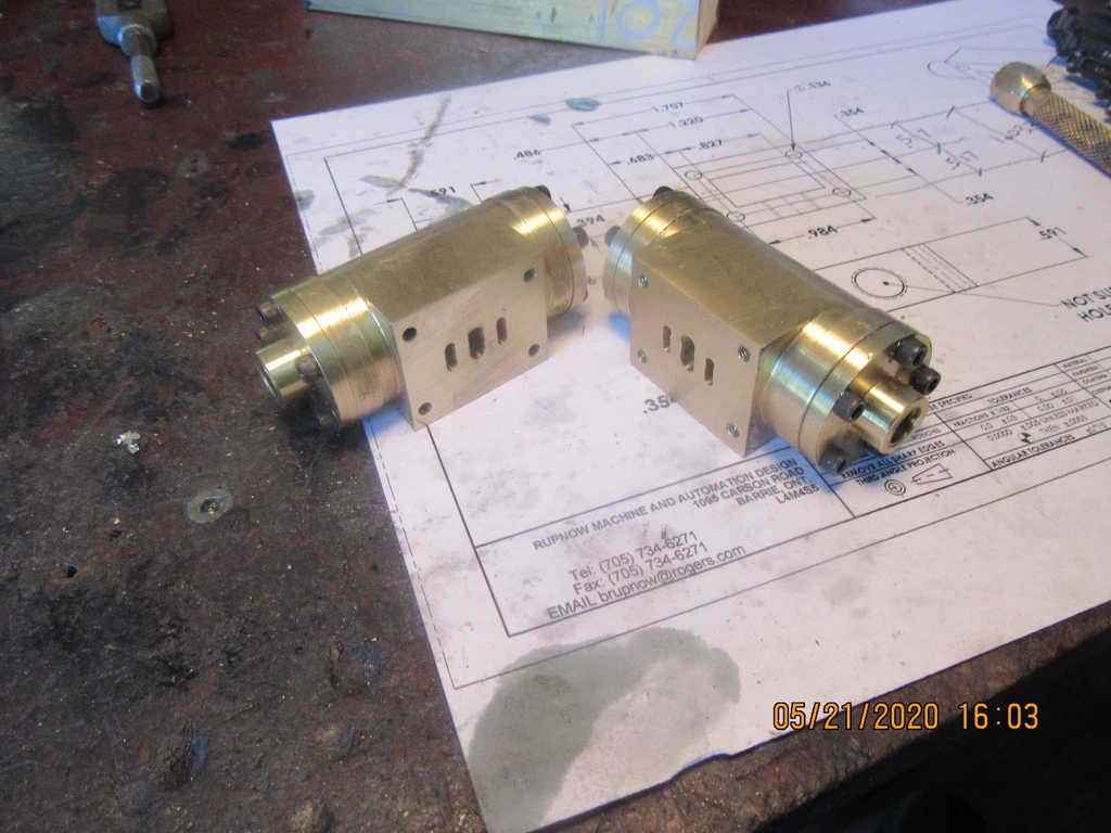
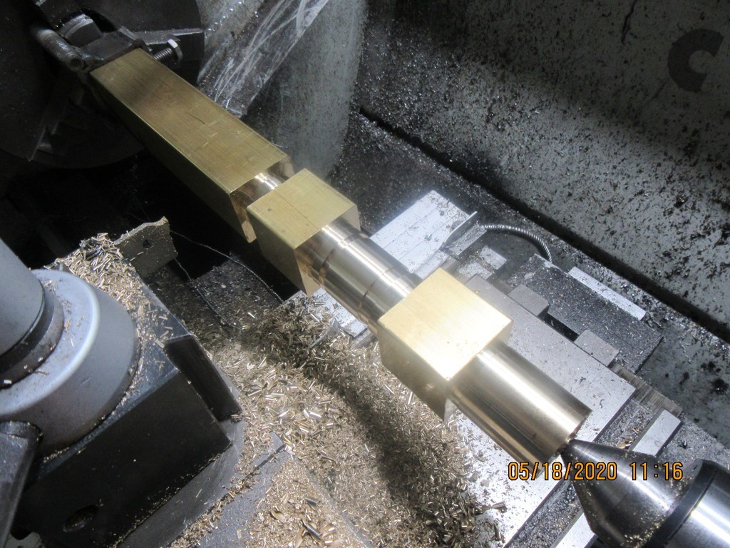
Now---If I've done this right, there should be two identical cylinders in there. It is set up so that each cylinder, when sawed from the square stock should be the right diameter and have a 1" long "spigot" attached to one end of each cylinder, to mount it in the three jaw chuck for boring. After the cylinder has been bored, the 1" stub length will be cut off and turned to give me four cylinder end caps.
j7OkXY.jpg
 
I am curious how you are going to take the square blocks down to round cylinders except for the flat on one side (for the steam valve housing). In the past I have soldered on (or used loctite) a flat piece after gouging out one side of the flat to match the curve of the cylinder.
 
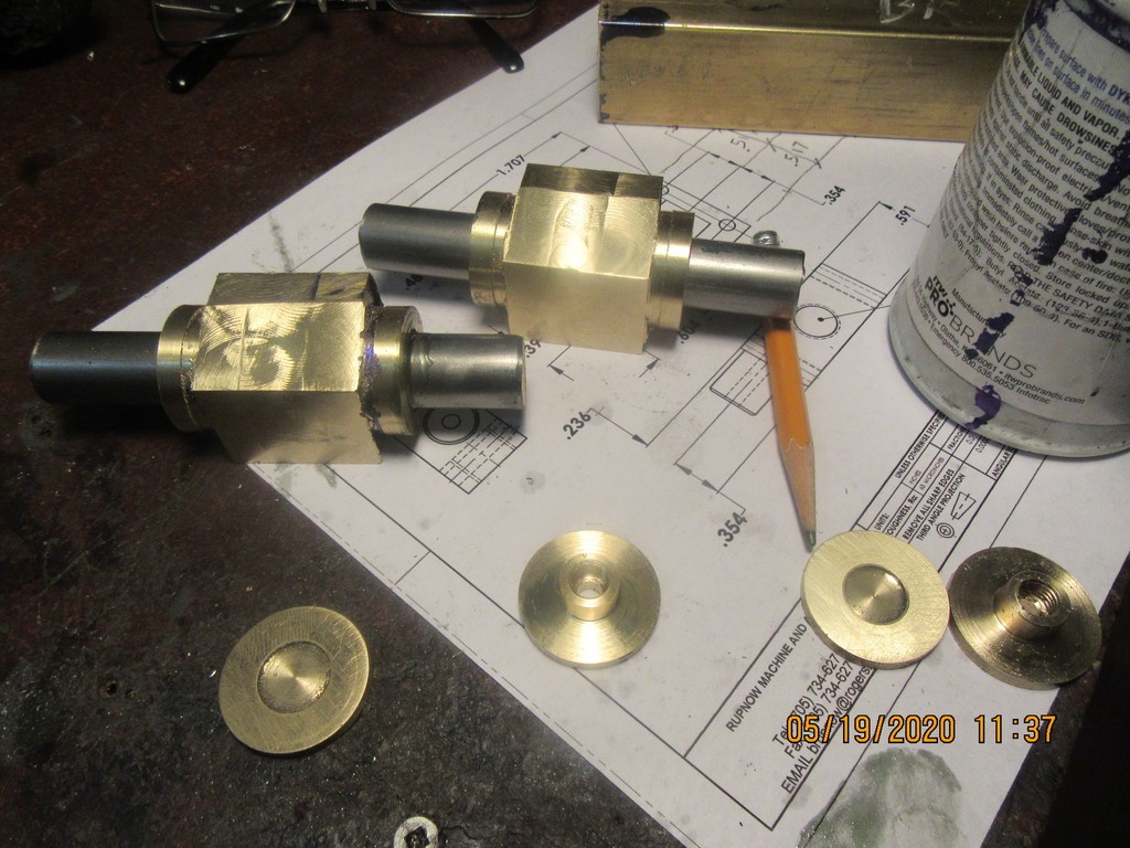
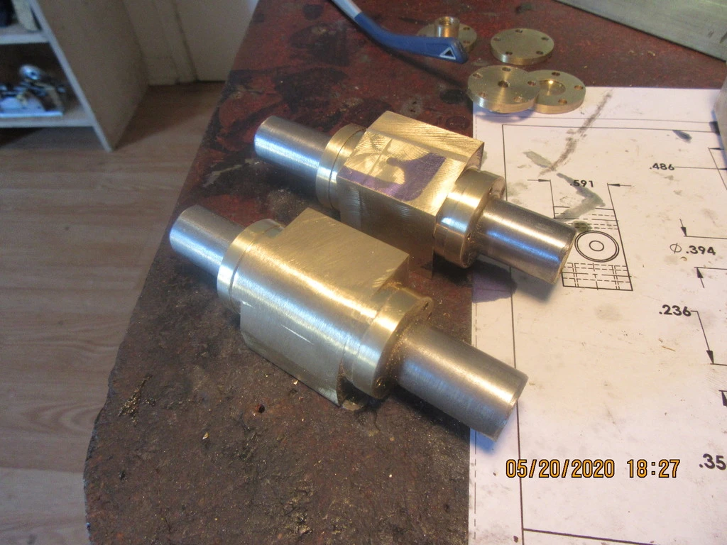
The outside of the rectangular areas of the cylinder have been machined this morning, all except for the radiused area. This was simple stuff, with the cylinders held in my milling machine vise. The rest of the things I have to do are mostly all rotary table work, so I need shafts mounted in each of the cylinders for my 3 jaw chuck on the rotary table to hold onto. I could have made an expanding arbor to mount the cylinders on, but this works just as well. I cut a couple of 5/8" cold rolled steel shafts, long enough to stick out each end about 1", and Loctited the shafts into place. After all my machining is finished, a bit of heat applied to the cylinders and the shafts slide right out. If any loctite residue remains in the cylinder it will easily come out by running a 5/8"reamer thru.
T2vU3r.jpg
 
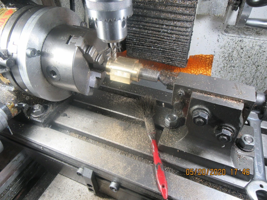
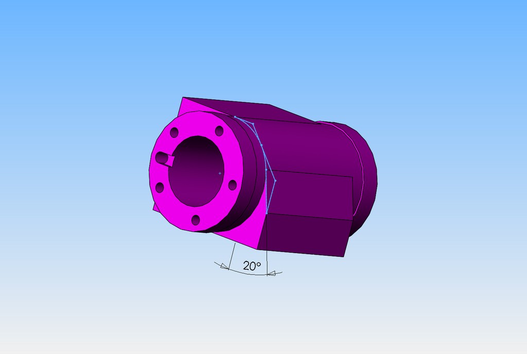
Shopgeezer was asking how I machined the radius on the cylinder. This is a picture of my set-up. I'm end-milling with a 1/4" diameter endmill. The endmill is cranked down until it contacts the part and is locked there. The travel stops on the front of the mill are set to keep me from running the endmill into the larger diameter bands at each end of the cylinder. The mill bed travels in the X axis to the extent of the travel stops, then cranked back, and the rotary table is indexed about three degrees, then repeat---and repeat---and repeat. Eventually you will have milled all the way around to the next "flat" surface on the cylinder. It will need a bit of file and sandpaper cleanup, but it works very well.
6Hg63s.jpg

Ehj7Cf.jpg
 
Last edited:
Sooooo, I now have an excuse to approach the financial officer with a proposal that I will cut down on the corn fries and energy drinks if I can buy the rotary table set I have been drooling over in the KBC catalog. I’ll just say its all Brian’s fault.
 
A rotary table with a set of bolt on divider plates is absolutely essential for making gears and so many other things. When I bought all my machine shop stuff about 12 or 13 years ago, I was told by the sales man that I absolutely needed one. I couldn't really see it then, but he was so right.
 
Hi Brian,
Nice work. Was the first operation to skim off a lot of the waste before setup in the rotary table and milling the round section. I acquired a small rotary table, but it is just that a rotary table. There is no means as standard to attach any indexing gear to it, there is an angle scale around its circumference. but I was "informed" that this wouldn't be accurate enough for making any gears on. Its an old myford one. I do have a dividing head, I just ain't finished building it yet.
 
Sorry the picture above I thought you had skimmed the corner off where the radius was going to go. As well as machining the faces, my bad, need better glasses!

Edit that post was meant to show post #46 in this thread, but I cant get it to quote to insert the pic......never mind
 
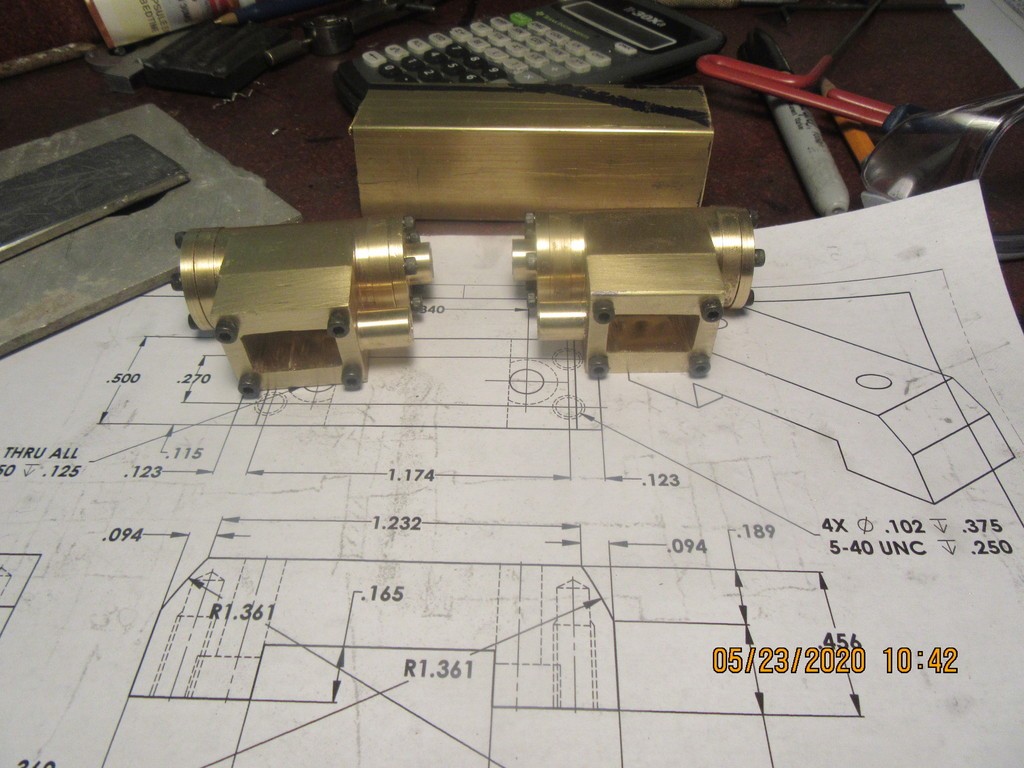
This morning I finished up the two steam chests. I had the outside machined yesterday, which involved 4 jaw set-up in my lathe to turn the round spigot. This morning I put the 4 holes in each corner and the cavity in the center. Once again the machining Gods smiled on me and everything bolts together!!
8PZFaH.jpg
 
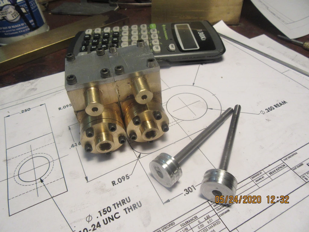
Today we have some steamchest covers and some pistons and piston rods. One noteworthy thing here---these small steam/air engines are not very forgiving of a non-concentric alignment between the pistons and piston rods. To get around that, I turn the pistons to 0.050" oversize, then screw the piston rod into the piston (they are both threaded #10-24) and coat the threads liberally with J.B. Weld. After it sets up for 24 hours, I will grip the 3/16" diameter piston rod in my lathes 3 jaw chuck, and finish turning the pistons to the correct sliding fit into the cylinders.
gKCHdi.jpg
 
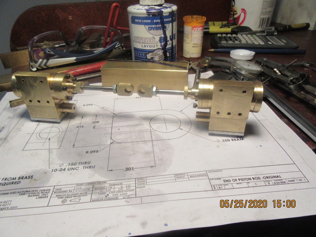
Nothing real exciting today. I turned down the pistons to finished size and made up the two rod glands that prevent air escaping around the piston rod. While I had the cylinders disassembled I finished off the internal porting in each cylinder. I made up the two brass rod ends and screwed them onto the piston rods. I took a couple of 8-32 hex nuts and rethreaded them to 10-24 because they are a bit smaller and look better. That doesn't sound like much, but I used up most of my day doing it. I just got back from my "fat mans walk" and it is very warm outside.
oYwRfS.jpg
 
If I walked 4 miles it would probably kill me. I'm having a rough time with arthritis this year. I think my walk now is about a mile and a half.
 
Back
Top