You are using an out of date browser. It may not display this or other websites correctly.
You should upgrade or use an alternative browser.
You should upgrade or use an alternative browser.
Old School Barstock 2 Stroke
- Thread starter Brian Rupnow
- Start date

Help Support Home Model Engine Machinist Forum:
This site may earn a commission from merchant affiliate
links, including eBay, Amazon, and others.
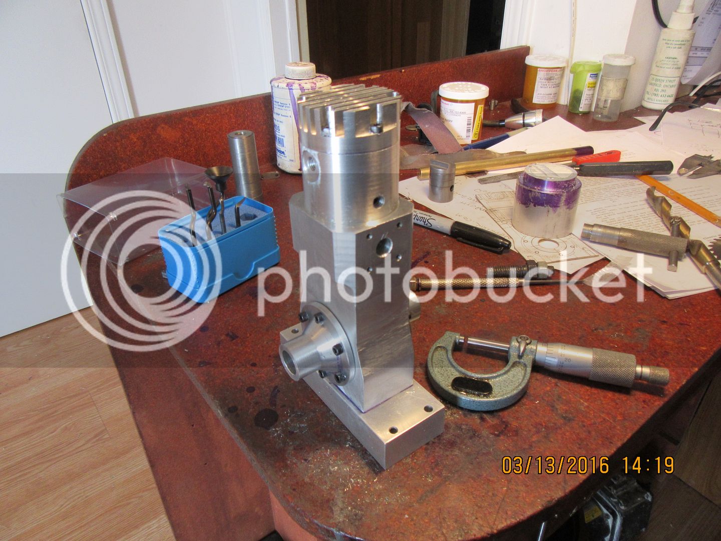
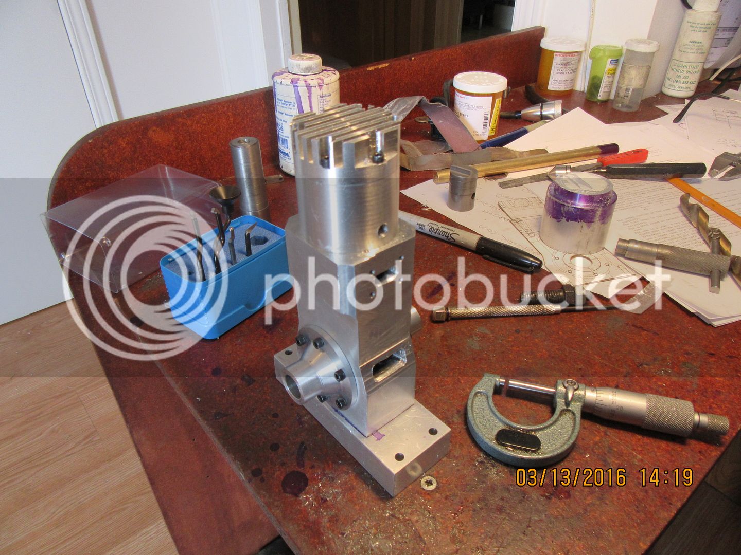
The original plans for this engine call for the intake manifold to be Loctited in place. Now don't get me wrong---I think Loctite is just great, and I use it on every engine I build.--However---On an overhung, cantilevered load like the carburetor, I want a couple of bolts holding it on. I just don't think Loctite is up to the task, so I have redesigned the intake manifold to attach with a couple of socket head capscrews. Now I will be able to make whatever carburetor adjustments are deemed necessary without having to worry about the whole thing falling off in my hand!!!
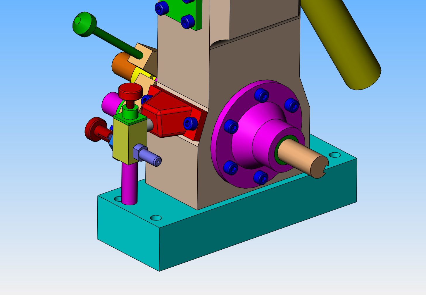

Finally I finished up the short term contract I was on and got to spend some time in my little shop. I have an intake port cover and an intake manifold. There are some very interesting angles on that intake manifold. I ordered the Loctite 574 flange sealant yesterday. I think I will make up an exhaust flange and a short length of exhaust pipe and then get into the crankshaft bushings, crankshaft, and con rod.
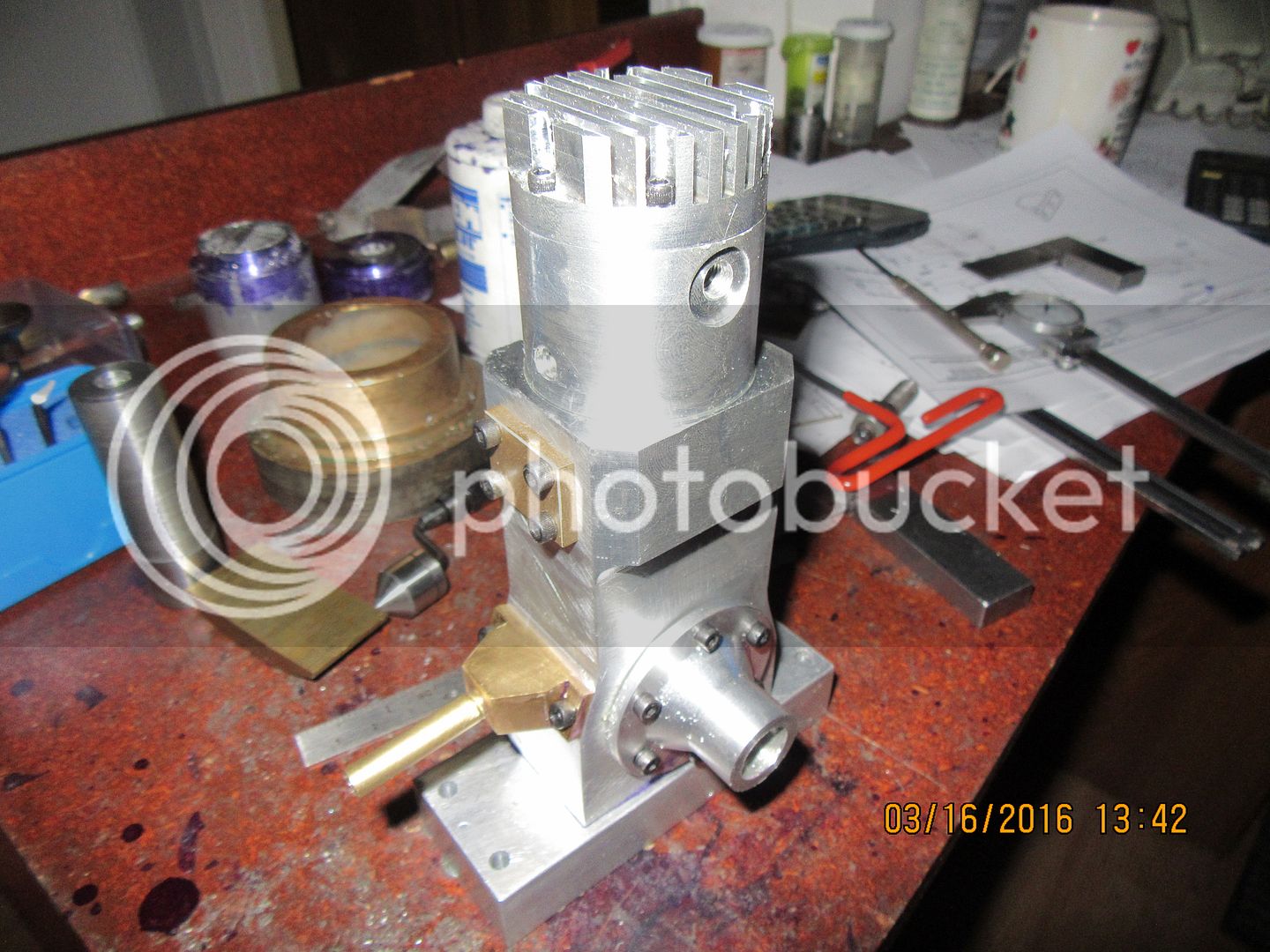

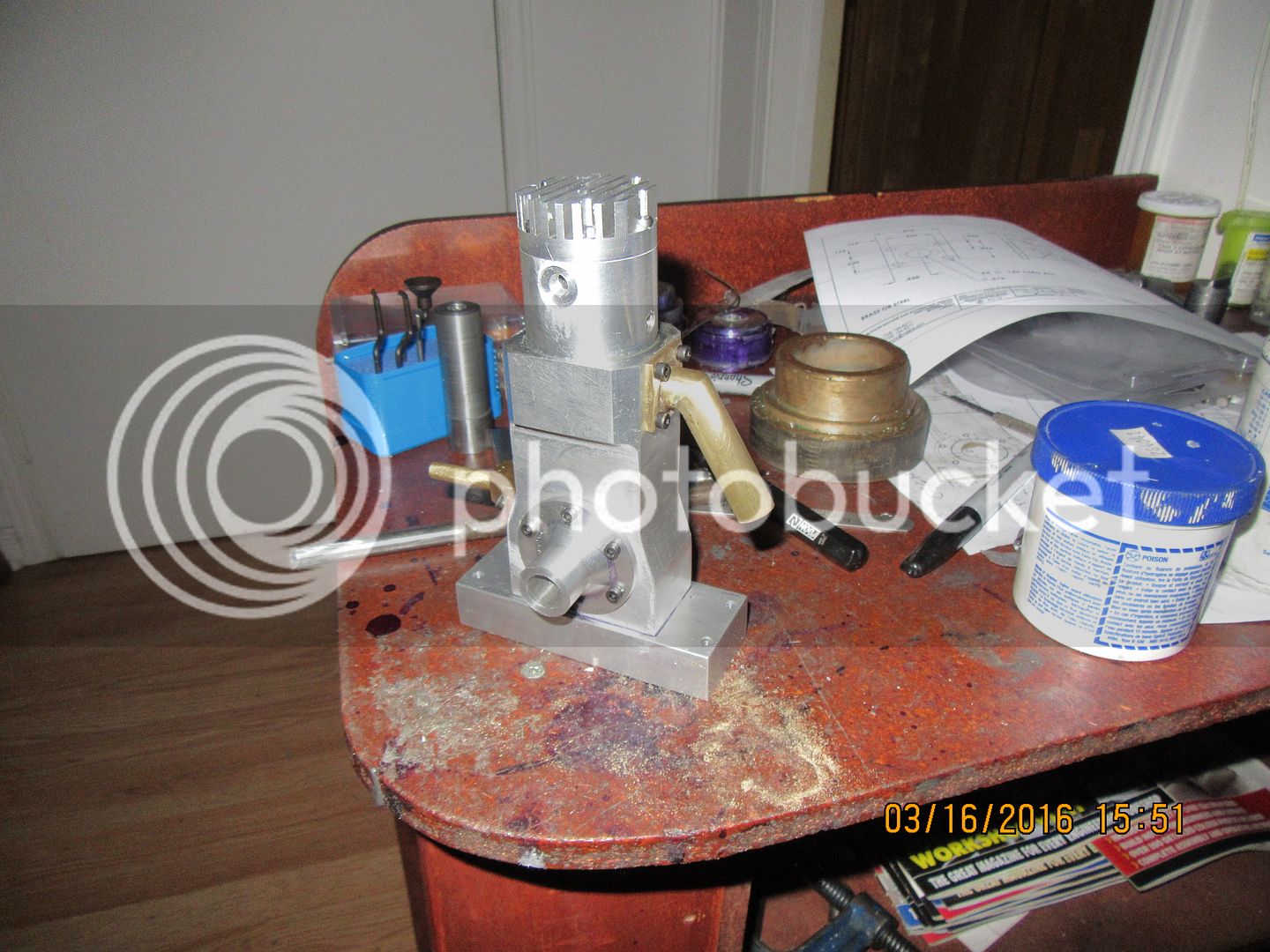
We have an exhaust flange and pipe!! It may need a bit of polishing, but it's all together and it fits. Damn!!! It looks huge, but it isn't really. That exhaust pipe is only 1/2" diameter, but the engine is so small that the pipe looks huge by comparison. I hate making soldered mitre joints like the one on that pipe. There is just never a good way to hold everything aligned and still have enough hands left to hold the torch and a piece of silver solder. I got it close and used a friendly file to make it straight after the fact. Tomorrow I can get down to some serious crankshaft stuff!!---Brian

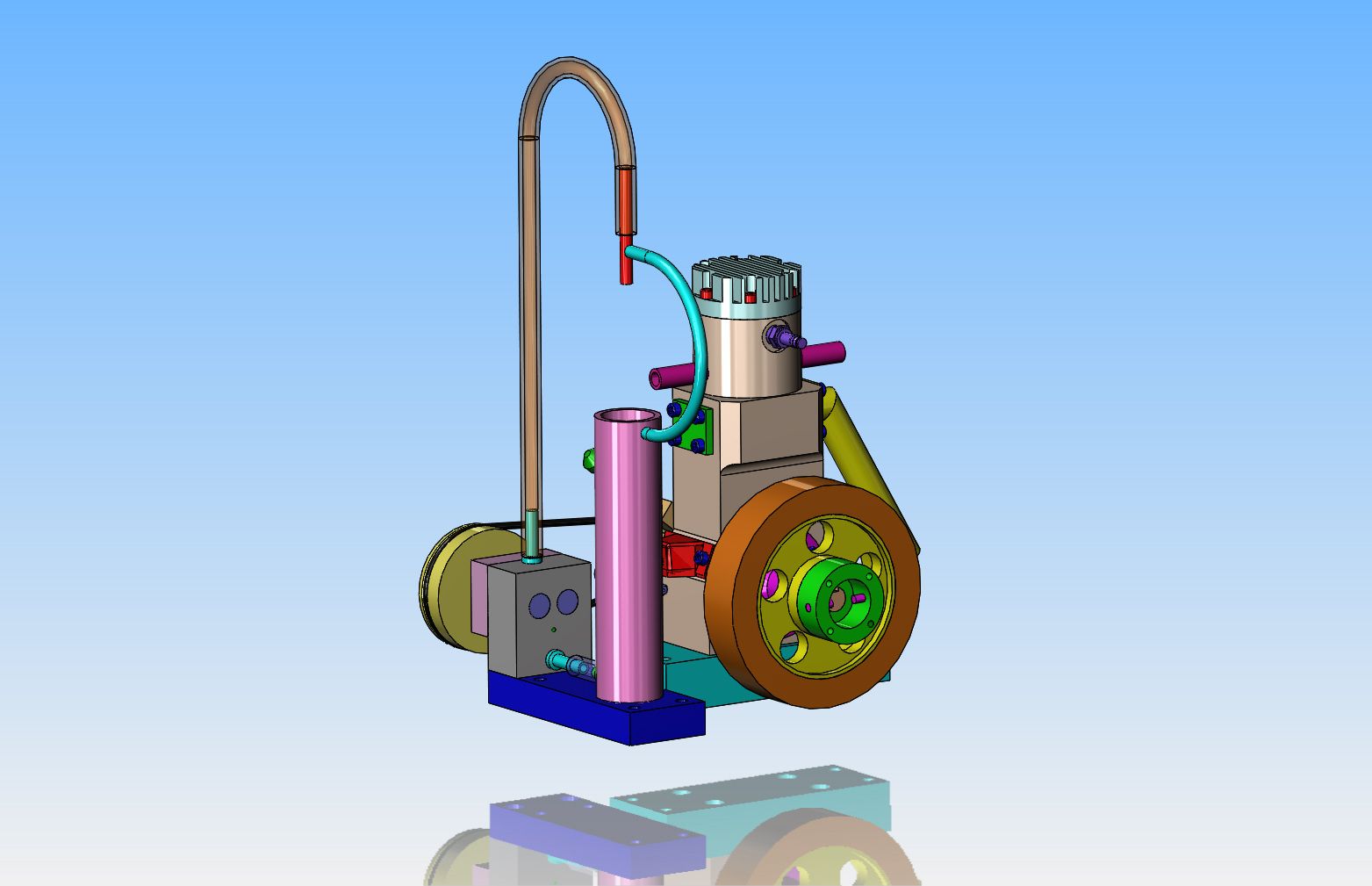
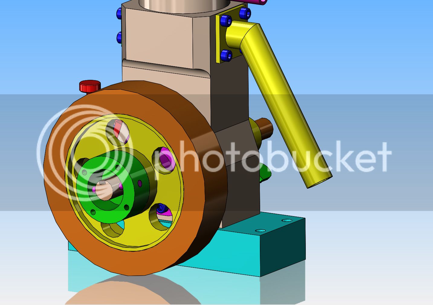
I had the best of intentions for today----But then we ended up with all four grandkids for half the day.---And, although Grandma kept the little devils all busy and I sneaked away to my shop, I got a distress call from a customer who needed a drawing immediately to send off to China to have something made. By the time I got that sorted out, I had a demand performance from all four grandkids to go with them and Grandma to get ice cream.--Dang, I never could turn down an ice-cream invite. So----all I really accomplished was a redesign of the flywheel. The center is aluminum. The outer rim is 660 bronze. The nifty looking green thing hanging from the front of the flywheel is made of steel, as are the two 1/8" diameter pins. That is the hub which I engage with my "starting tool" in my variable speed drill to start the engine. (The 1/8" diameter pins don't go through the end of the crankshaft, they just set up against it. They are pressed and Loctited into the green ring.)


$39.58
$49.99
Becker CAD 12 3D - professional CAD software for 2D + 3D design and modelling - for 3 PCs - 100% compatible with AutoCAD
momox Shop

$519.19
$699.00
FoxAlien Masuter Pro CNC Router Machine, Upgraded 3-Axis Engraving All-Metal Milling Machine for Wood Acrylic MDF Nylon Carving Cutting
FoxAlien Official

$45.99
Sunnytech Mini Hot Air Stirling Engine Motor Model Educational Toy Kits Electricity HA001
stirlingtechonline
![DreamPlan Home Design and Landscaping Software Free for Windows [PC Download]](https://m.media-amazon.com/images/I/51kvZH2dVLL._SL500_.jpg)
$0.00
DreamPlan Home Design and Landscaping Software Free for Windows [PC Download]
Amazon.com Services LLC

$99.99
AHS Outdoor Wood Boiler Yearly Maintenance Kit with Water Treatment - ProTech 300 & Test Kit
Alternative Heating & Supplies

$94.99
$109.99
AHS Woodmaster 4400 Maintenance Kit for Outdoor Wood Boiler Treatment
Alternative Heating & Supplies

$39.99
$49.99
Sunnytech Low Temperature Stirling Engine Motor Steam Heat Education Model Toy Kit For mechanical skills (LT001)
stirlingtechonline

$89.99
Outdoor Wood Boiler Water Treatment Rust Inhibitor- AmTech 300 & Test Kit
Alternative Heating & Supplies

$24.99
$34.99
Bowl Sander Tool Kit w/Dual Bearing Head & Hardwood Handle | 42PC Wood Sander Set | 2" Hook & Loop Sanding Disc Sandpaper Assortment | 1/4" Mandrel Bowl Sander for Woodturning | Wood Lathe Tools
Peachtree Woodworking Supply Inc
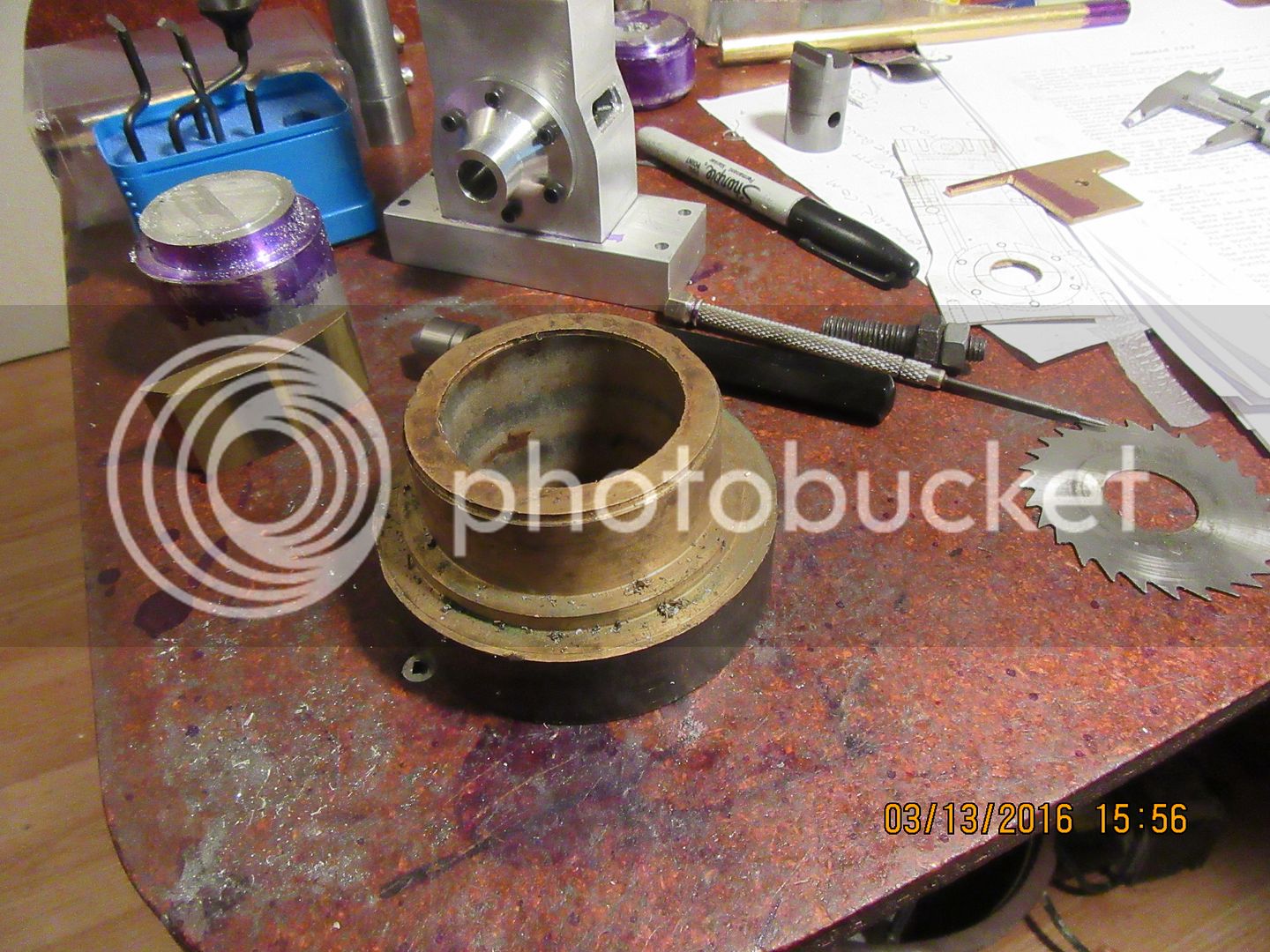
A little help please. The picture posted is from the original plan set for this engine. The part with the black dashed line around it is the bushing which fits into the coned crankshaft bushing support, one on each side of the engine. I can see that a groove for oil is asked for---I'm just not sure about how I would make a groove like that, and it also appears to run up the face of the disc which is formed at the inner end of the bushing. The finished bore on my bushings will be only 3/8". It's not inconceivable that I could grind a small tool to fit in my quick change tool holder and hold the bushing stationary in the 3 jaw chuck and "broach" a blind v-groove into the bushing. It couldn't run all the way through, or the crankcase vacuum would pull air in through the groove, which would be a big no-no. As for the groove that appears to run up the face of the disc, would it just be one radial line, or a spiral groove, or does it even need to be there at all? I may just decide not to put the groove in there at all. After all, the fuel has oil mixed with it, and may well be sufficient to lubricate the bushing without any kind of groove there. What do you think?---Brian
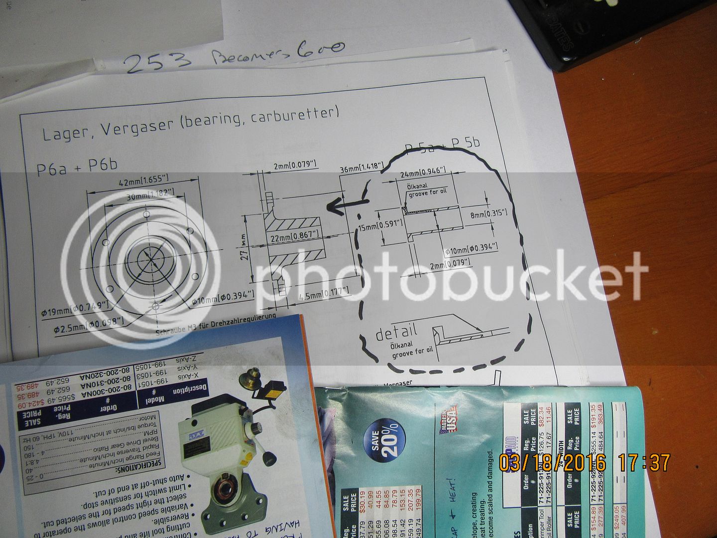

With the bush fully turned and bored including the end flange (but not yet lapped*) I would grip it lightly in the milling vice by the ends and cut the groove with a small (1/16") slot drill. This would also form the port in the middle of the bush and the radial connecting channel in the flange as a half-round groove. A centre drill (slocombe bit) would mill the chamfered cup at the edge.
An easier way to get an oil hole might be to drill at an angle after the bush is assembled in the bearing housing, drilling so as to safely not break through the
exterior conical surface.
*
An easier way to get an oil hole might be to drill at an angle after the bush is assembled in the bearing housing, drilling so as to safely not break through the
exterior conical surface.
*
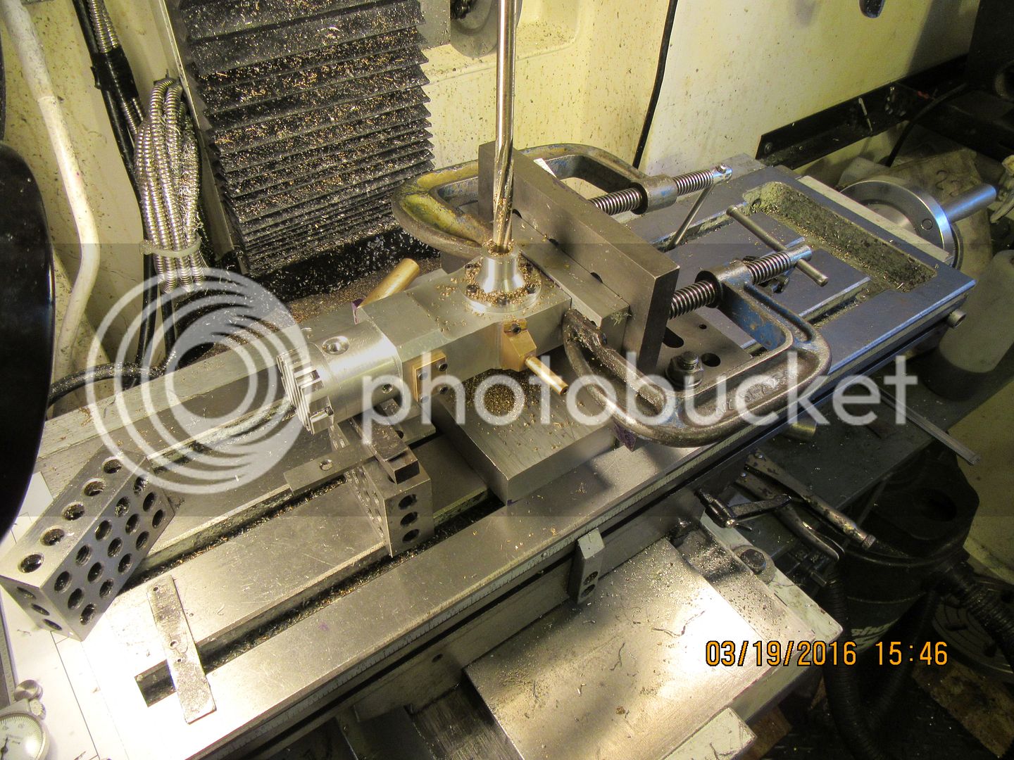
When I installed the bushings into the cone shaped bushing housings, I reamed them individually to 5/16" diameter. After the coned housings were bolted to the sides of the main body, I set everything up with an angle plate to ensure that the underside of the base-plate was truly square to the center of the spindle. A packer plate underneath the base ensured squareness in the other plane. Then I centered the spindle on the top-most bushing, and drilled thru the entire assembly with a 11/32" drill, then reamed through both bushings to 0.375". Of course, this then demanded an "assembly shot" with the flywheel in place. The flywheel is 95% finished. That's not really a crankshaft in the engine. It's just a piece of 3/8" round cold rolled.


Naiveambition
Well-Known Member
- Joined
- May 15, 2012
- Messages
- 369
- Reaction score
- 95
Brian, Sorry to break off your thread but I seen your slitting saw holder and was wandering. If you can elaborate on it a little. From the looks you have a small mandrel fitted inside of a normal end mill holder. Is this correct?
I've been tossing the idea around to build one but have not found too much info on them. I like your approach in that I can gain extra distance vs a collet. On my mill the spindle is very short and I spend most of my time struggling to see the work with collets.
Are their plans or just worked up for what was needed.
Thanks.
Mike
Mike--I'm not sure where you are in the world, but I bought my slitting saw arbor at Busy Bee Tools in Barrie, Ontario. They are relatively inexpensive, and will fit two or three different hole sizes. They have a 1/2" shank.---Brian
http://www.busybeetools.com/products/arbor-slitting-saw.html
http://www.busybeetools.com/products/arbor-slitting-saw.html
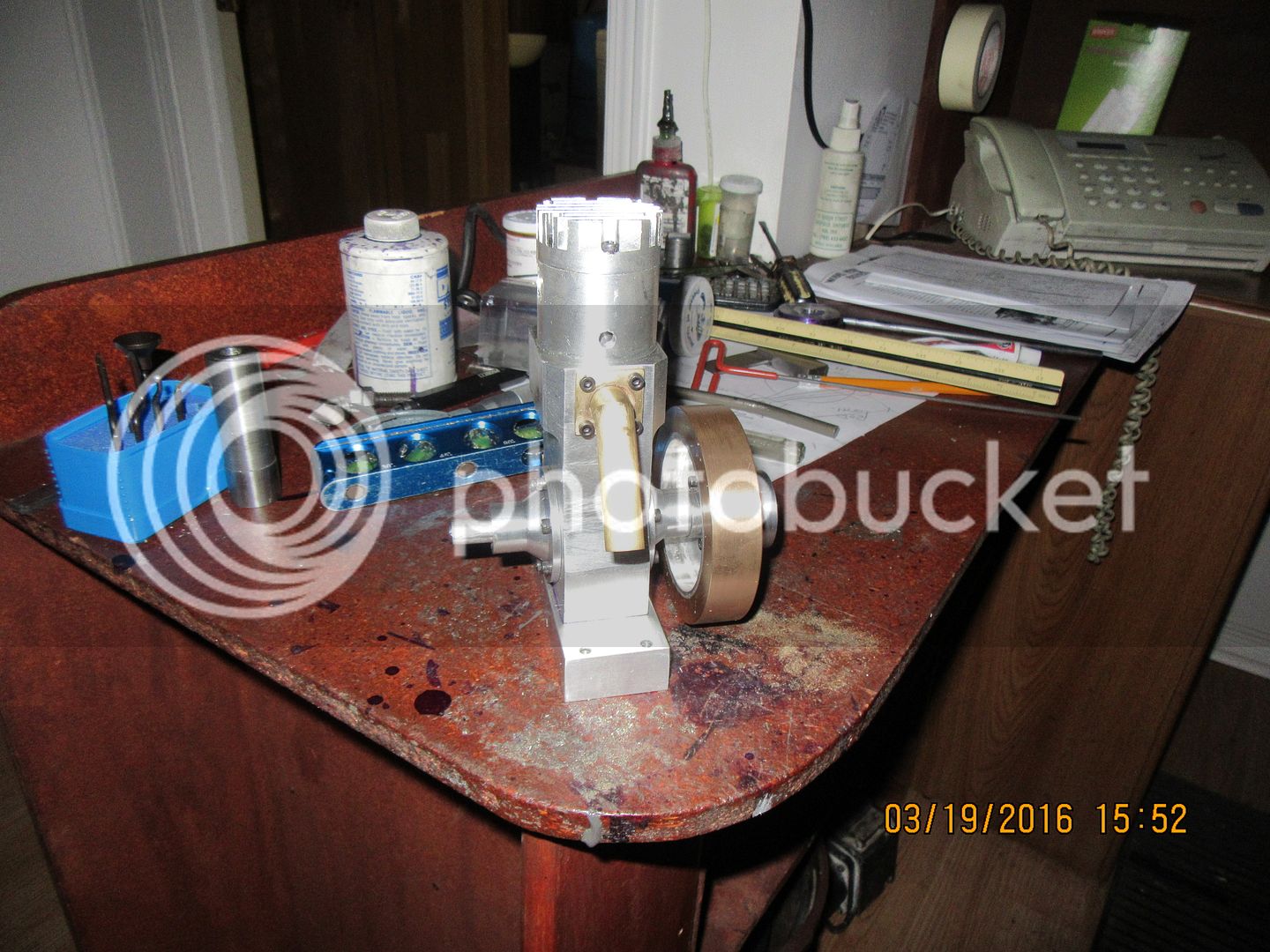
At this point the flywheel is finished. I find that my jar of #8 set screws is empty, so for the moment I have a couple of #8 socket head caps stuck in where the set screws would normally go. You can see the steel ring mounted to the face of the flywheel with the two 1/8" dowel pins Loctited into it, and my "starter spud" laying on the bench in the foreground. The starter spud fits into my variable speed drill, and disengages very easily as soon as the engine has started. I came up with this method of starting engines about half an hour after building my first i.c. engine and flipping the flywheel by hand until my wrist was sore. Now I move on to the crankshaft. There is a certain method to my sequence in making these parts. I needed the crankshaft bushings machined and installed for the crankshaft to fit into, and I needed the flywheel so I will have something which I can hold by hand to turn the crankshaft once it is in place to check for clearances.
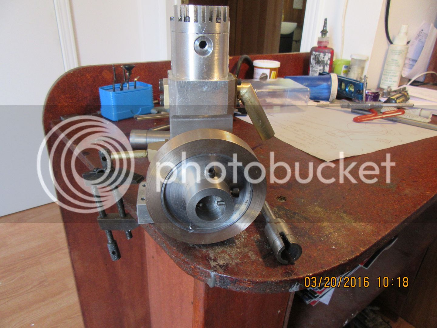

I've been very "cranky" this afternoon. The crankshaft is a two piece unit. The end with the rod journal is the end with the flywheel on it. The other end of the crankshaft is "driven".--It gets the ignition cam on it. To install the crankshaft, the two coned bushing supports unbolt from the main housing, and each half of the crankshaft gets pushed through from the inside end of the bushing supports, then they get bolted back onto the main body.--Hopefully, I will soon have a con-rod to assemble there as well.
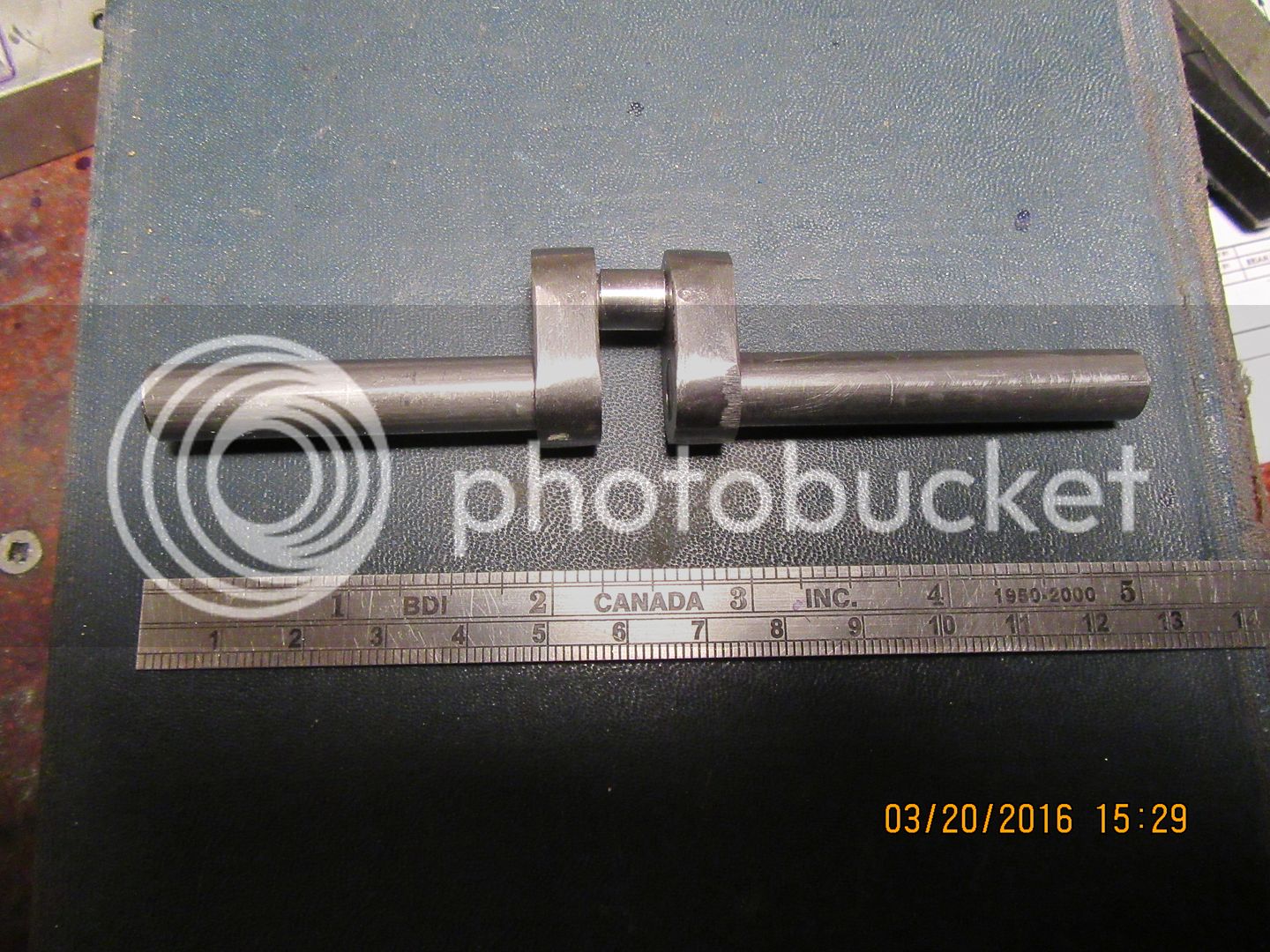
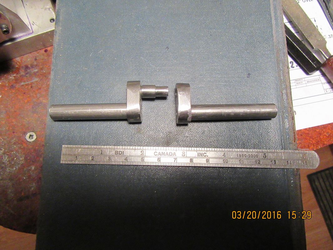


Once again I have proven to myself that the size of a part in no way reflects the amount of work required to make it!!! However, we now have a connecting rod. The crankshaft is mounted in the engine, and after much fettling, clearancing, dissasembly and reassembly , it goes round and round and doesn't hit anything. I still have to pull it out of the engine (which pretty well demands complete disassembly) and put the keyway in the end of it, then reassemble it with the piston and con rod and hope that everything still goes round and round and up and down.
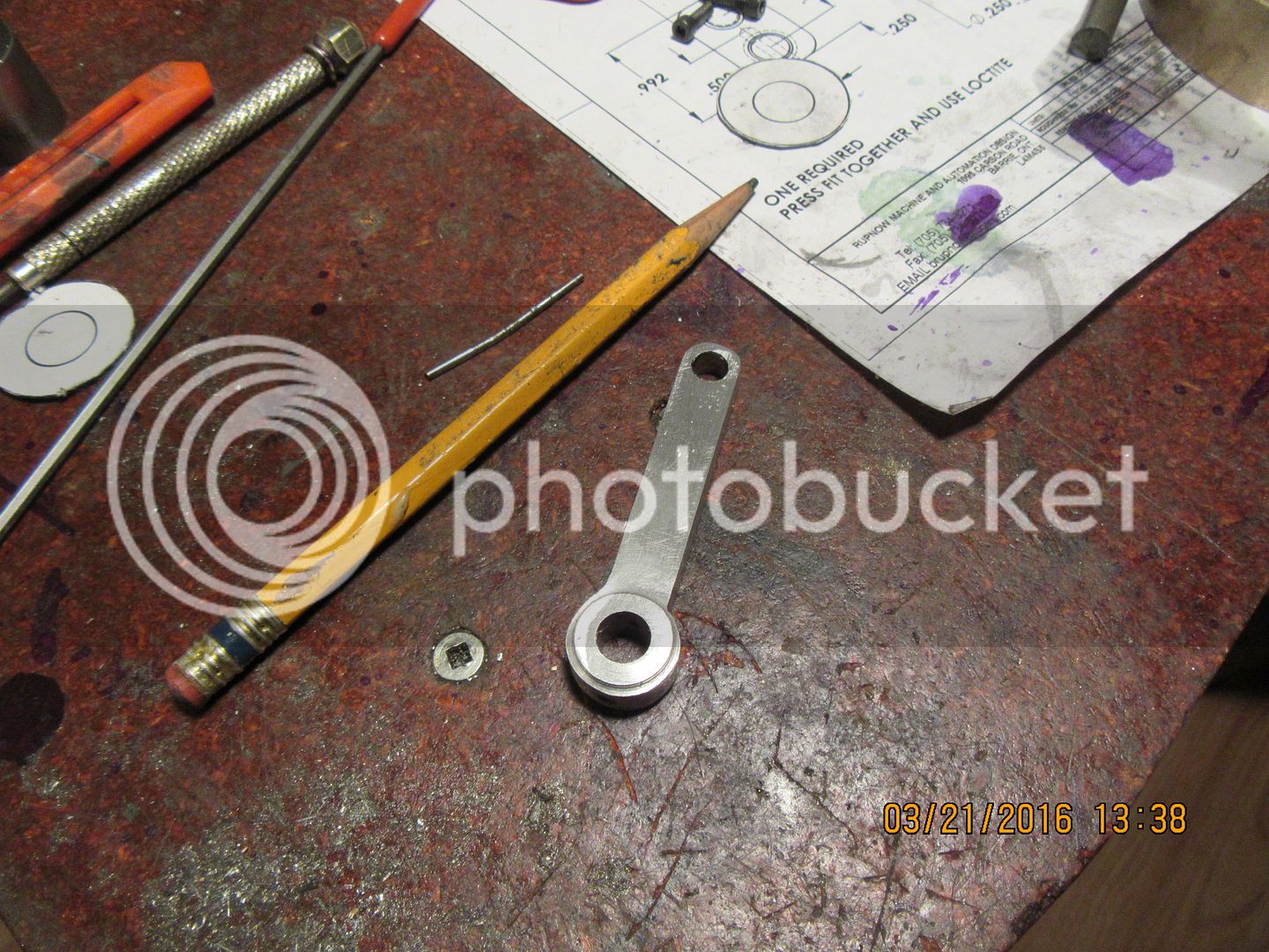

News is not good!! When I pressed the rod journal into my 3 piece "driving" crankshaft, it pressed awful hard. I thought afterward that it looked a little crooked, but decided to move forward with other things. Now that I have the rod finished, I have confirmed my fears. With the crankshaft in my 3 jaw and the lathe on it's lowest speed. and the con rod in place on the journal, the con rod has kind of a snaky, twisting motion as the crankshaft revolves, not a true linear motion like it should have. This is not a major disaster, as the rod journal can be pressed out and a new one turned up and pressed in. The next one will have a much longer "lead" on the side that gets pressed into the crank "throw".
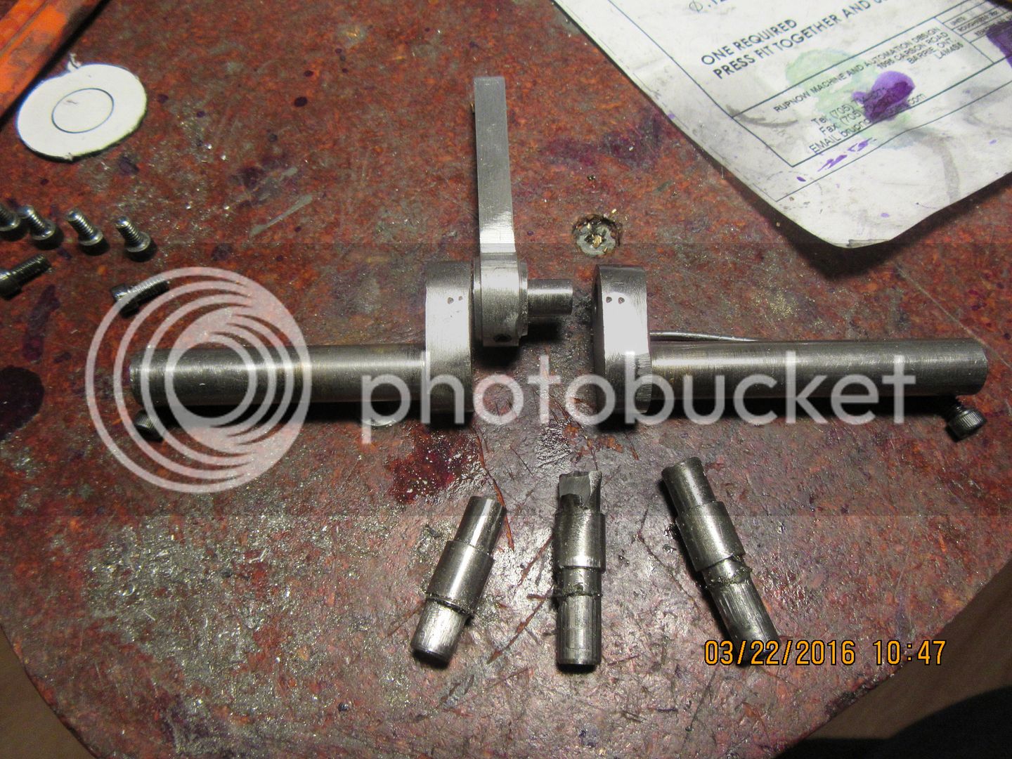
This post is not meant to show me up as a fool, although some are apt to take it that way. I have had an absolute devil of a time to get the con-rod journal pressed into place in the crankshaft "throw" and get it to press in straight. I finally succeeded, but not without my fair share of frustration. The journal is made from 5/16" diameter cold rolled round stock. The "throw" is made from 5/16" thick cold rolled steel bar. The bad journal on the left, had no lead and was .004" oversize. It did press all the way in, but ended up crooked---it pressed VERY hard. I was using my 4" mechanics bench vise to press things together. The bad journal next to it had a lead at 0.250" diameter and a diameter of 0.253 in the area to be pressed. It pressed in to about 3/4 of the way, and then it too began to go crooked and was VERY hard to press. The third one on the right had a 0.250" diameter lead and was turned to 0.252" diameter in the press area. It pressed in VERY hard, and hung up and began to go crooked at about 3/4 of the way into place. The final, and successful one was turned to have a lead of about 0.249" diameter, and a diameter of 0.2515 in the area to be pressed. It went in VERY hard, but it went in straight. the "lead" area was then trimmed off on my bandsaw.

So---Today we reached a "milestone" event in the development of this engine!! The wrist pin with it's brass end-caps was finished and installed earlier today. The piston with con rod connected was dropped down thru the top of the engine and when the big end of the con-rod was visible in the crankshaft area, the coned bushing housings and both halves of the crankshaft were assembled. Everything goes "round and round and up and down" just as I had hoped for. No, it wasn't really that simple. I kept finding minor interferences, chasing them down, removing them, and reassembling things, until eventually the crankshaft would rotate a full 360 degrees without anything inside going "clunk clunk". I have the Loctite 574 on order for sealing the leaded steel cylinder liner into the main aluminum body. All that is outstanding now is the bracket for attaching the ignition points, the ignition cam, and the carburetor, and of course some kind of fuel tank. I plan on using the gear pump I designed and built last year to circulate cooling water thru the engine, and it will be driven by an o-ring drive belt.
canadianhorsepower
Well-Known Member
- Joined
- Oct 22, 2011
- Messages
- 1,671
- Reaction score
- 324
The bad journal on the left, had no lead and was .004" oversize.
Brian why go so big all you need for a press fit is .001
coming along good
Luc--I don't have a lot of experience with press fits. My big concern is that when the engine fires, if the piece the con-rod is connected to comes lose, the engine will be destroyed. I find that my press fits are dramatically effected by the surface finish on the part being pressed. If the male part has a rough finish, then the press fit won't be too good because of all the micro-ridges on the part (they give a rather false reading on the micrometer.) If the part has a good finish, then it will be a much harder press even though it measures the same diameter as the part with the rough finish. A lot of what I am doing is "learn by experience" machining. Next time I go for a press fit on parts 1/4" in diameter, I will remember this exercise and go for a .001" over nominal size.
Similar threads
- Replies
- 14
- Views
- 8K


