You are using an out of date browser. It may not display this or other websites correctly.
You should upgrade or use an alternative browser.
You should upgrade or use an alternative browser.
Old School Barstock 2 Stroke
- Thread starter Brian Rupnow
- Start date

Help Support Home Model Engine Machinist Forum:
This site may earn a commission from merchant affiliate
links, including eBay, Amazon, and others.
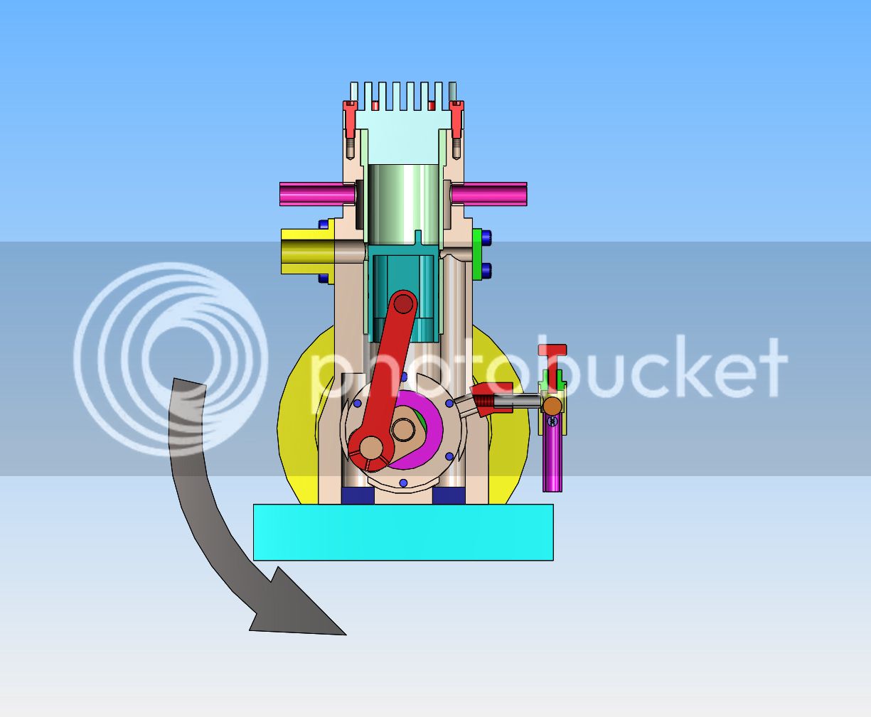
I have a question now, that won't really have any effect on the way things get built, but may ultimately effect the way things get assembled. As you can see in this section view, the slot milled into the side of the crankcase to admit air/fuel mix is on an angle. If the engine rotates in the direction I have shown with the black arrow, it seems to me that there will be a pressure wave built up in front of the revolving crankshaft that will try to force incoming air fuel mix back out of the crankcase. Conversely, if the rotation is opposite to what I show, then there should be an area of low pressure behind the revolving crankshaft that will actually help to pull air/fuel mix into the crankcase. Since the engine is symmetrical about the centerline, I can choose which side I put the flywheel on and thus determine the direction of rotation. I like my engines to revolve clockwise when viewed from the flywheel side, because I use a starter spud in my variable speed drill to start my engines, which engages with a slotted hub attached to the flywheel. If the engine revolves counter-clockwise, then the drill chuck will loosen off. Is what I'm saying valid, or am I over-thinking things??

canadianhorsepower
Well-Known Member
- Joined
- Oct 22, 2011
- Messages
- 1,671
- Reaction score
- 324
I have a question now, that won't really have any effect on the way things get built, but may ultimately effect the way things get assembled. As you can see in this section view, the slot milled into the side of the crankcase to admit air/fuel mix is on an angle. If the engine rotates in the direction I have shown with the black arrow, it seems to me that there will be a pressure wave built up in front of the revolving crankshaft that will try to force incoming air fuel mix back out of the crankcase. Conversely, if the rotation is opposite to what I show, then there should be an area of low pressure behind the revolving crankshaft that will actually help to pull air/fuel mix into the crankcase. Since the engine is symmetrical about the centerline, I can choose which side I put the flywheel on and thus determine the direction of rotation. I like my engines to revolve clockwise when viewed from the flywheel side, because I use a starter spud in my variable speed drill to start my engines, which engages with a slotted hub attached to the flywheel. If the engine revolves counter-clockwise, then the drill chuck will loosen off. Is what I'm saying valid, or am I over-thinking things??
]
Brian;
it doesn't matter, a two stroke is like a balloon , apply pressure somewhere and you will have a result o the other end
cheers
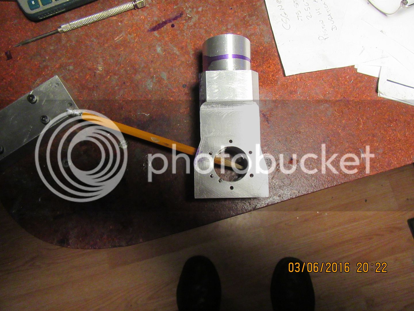
I may have answered my own question here. The pencil stuck thru the slot is pretty well lined up with the center of the crankshaft, so it shouldn't make any difference which way the engine rotates. What I said in my previous post would only hold true if the intake slot came through tangent to one of the crankcase walls.--I'm still confused though, about which direction this engine should rotate.--can anyone tell from the cut away view in my previous post which way this engine should rotate?--My lack of knowledge about two stroke engines is hanging out here---

- Joined
- Feb 17, 2008
- Messages
- 2,330
- Reaction score
- 445
Brian,
In the for what it's worth department, all the drill motors that I have seen that have a reverse rotation on them have a locking screw on the chuck to prevent it from unscrewing. If you open the chuck jaws and look into the chuck between the jaws you will see it. It is typically a cross point screw and must be removed to loosen or remove the chuck. If you ever decide to change chucks or salvage a chuck you need to know that this screw has a LEFT hand thread.
Gail in NM
I think most two strokes run well i n either direction. I had a full size 1908 Gray one cylinder marine engine in a boat- much like the hubbard this project is based on. It ran in either direction, had a direct coupled prop and the way to reverse rotation was to change the spark timing and hit the switch at the right time.
I also remember my old glow plug model airplane engines would start in the wrong direction about half the time.
I also remember my old glow plug model airplane engines would start in the wrong direction about half the time.

$39.99
$49.99
Sunnytech Low Temperature Stirling Engine Motor Steam Heat Education Model Toy Kit For mechanical skills (LT001)
stirlingtechonline

$12.56
$39.95
Complete Plans for Building Horse Barns Big and Small(3rd Edition)
ThriftBooks-Atlanta

$519.19
$699.00
FoxAlien Masuter Pro CNC Router Machine, Upgraded 3-Axis Engraving All-Metal Milling Machine for Wood Acrylic MDF Nylon Carving Cutting
FoxAlien Official

$45.99
Sunnytech Mini Hot Air Stirling Engine Motor Model Educational Toy Kits Electricity HA001
stirlingtechonline

$24.99
$34.99
Bowl Sander Tool Kit w/Dual Bearing Head & Hardwood Handle | 42PC Wood Sander Set | 2" Hook & Loop Sanding Disc Sandpaper Assortment | 1/4" Mandrel Bowl Sander for Woodturning | Wood Lathe Tools
Peachtree Woodworking Supply Inc

$89.99
Outdoor Wood Boiler Water Treatment Rust Inhibitor- AmTech 300 & Test Kit
Alternative Heating & Supplies
![DreamPlan Home Design and Landscaping Software Free for Windows [PC Download]](https://m.media-amazon.com/images/I/51kvZH2dVLL._SL500_.jpg)
$0.00
DreamPlan Home Design and Landscaping Software Free for Windows [PC Download]
Amazon.com Services LLC

$39.58
$49.99
Becker CAD 12 3D - professional CAD software for 2D + 3D design and modelling - for 3 PCs - 100% compatible with AutoCAD
momox Shop

$94.99
$109.99
AHS Woodmaster 4400 Maintenance Kit for Outdoor Wood Boiler Treatment
Alternative Heating & Supplies

$99.99
AHS Outdoor Wood Boiler Yearly Maintenance Kit with Water Treatment - ProTech 300 & Test Kit
Alternative Heating & Supplies
Thank you Gail and Ron--I am considering using glow fuel and a glow plug for this engine. According the the information sheet I have, it will run quite well on glow fuel. It has a 6.5:1 compression ratio. How do you time an engine running a glow plug? I know how to advance or retard the ignition when it is fired by a sparkplug running a gasoline based fuel, but since a glow plug (continuous glow is called for), how does it know when to ignite the fuel/air mix?
CR 6.5:1(at full stroke?) is quite low for glow engine. Running on plain methanol/castor fuel mix will needed Hot (or hotter four stroke) plug.
Ignition timing is set by changing type of plug,amount of nitromethane in fuel,CR and richness of fuel/air mixture.
Ignition timing is set by changing type of plug,amount of nitromethane in fuel,CR and richness of fuel/air mixture.
- Joined
- Jun 24, 2010
- Messages
- 2,455
- Reaction score
- 974
I... there will be a pressure wave built up in front of the revolving crankshaft that will try to force incoming air fuel mix back out of the crankcase. http://s307.photobucket.com/user/Br...ASSY-WITH ROTATION ARROW_zpsnbrbbugr.jpg.html
The predominant force that makes the (ambient pressure) fuel intake charge 'move' into the crankcase cavity is caused by the reduced pressure (suction force) created by the piston displacement. I suspect the reciprocating & rotating parts are basically just stirring turbulent gas & probably not real effective at that.
https://www.google.ca/search?q=2+st...LAhUW0GMKHSKqB4oQsAQIIQ#imgrc=kF-C0SBgBYs2ZM:
canadianhorsepower
Well-Known Member
- Joined
- Oct 22, 2011
- Messages
- 1,671
- Reaction score
- 324
Brian,
why don't you take a few second and read the book that
I posted in the download section
It is well documented and there is graph explaining everything.
cheers
why don't you take a few second and read the book that
I posted in the download section
It is well documented and there is graph explaining everything.
cheers
Last edited:
No progress on the engine for the last couple of days. I have one customer in town who periodically has work for me, but insists that it be done on his premises. He keeps an office and a computer for my use only. After spending most of the winter cooped up at home, I'm quite happy to get out of the house for a few days. However, after spending 8 hours over at his plant, I don't have a lot of energy left for machining in the evenings.
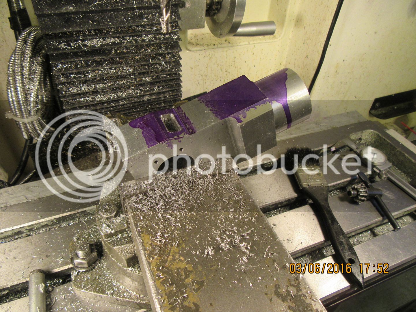
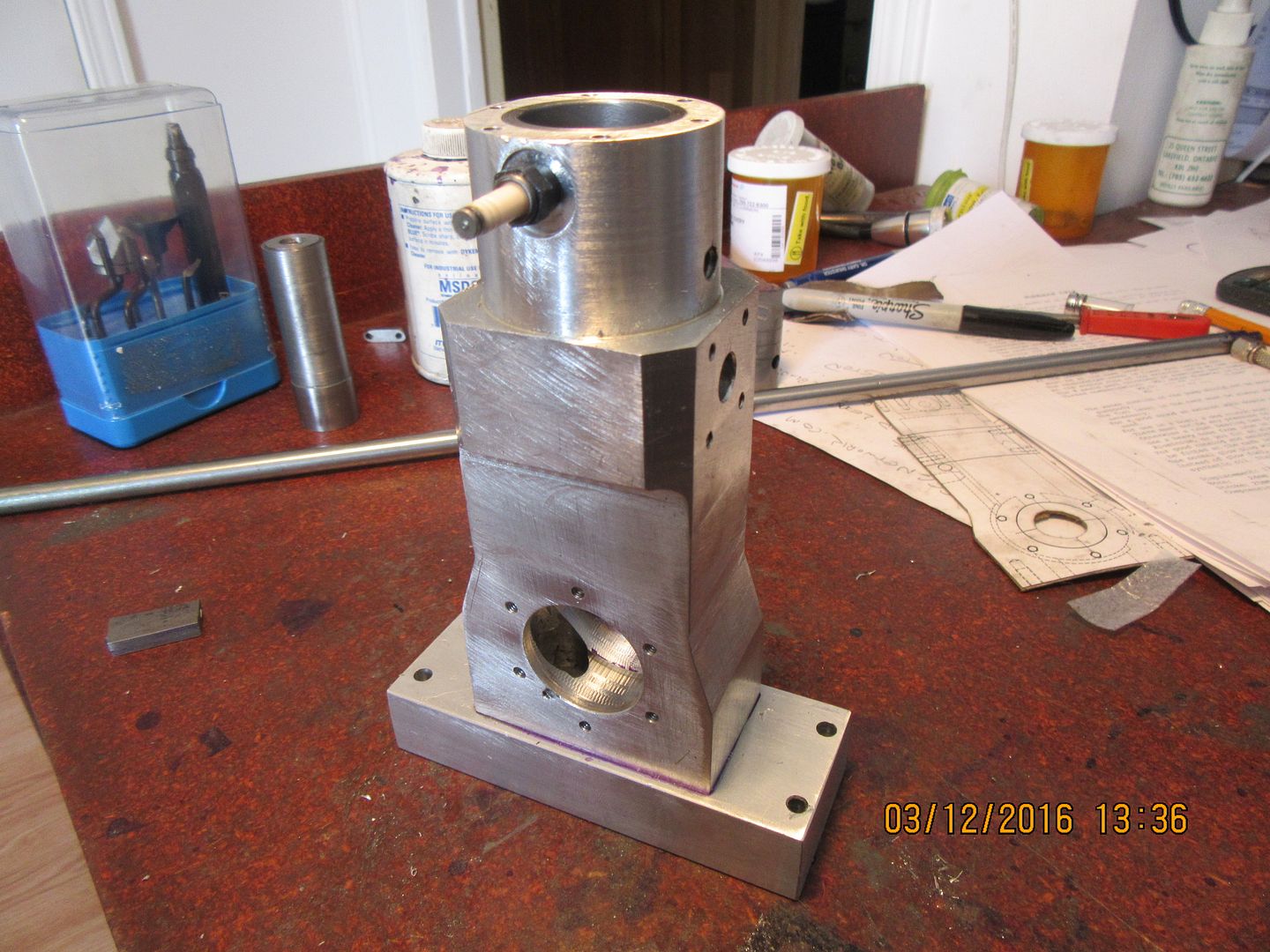
This morning I finished all of the holes, slots, and threaded holes in the main body. All went well, and I'm happy to be done with it. I have been so busy at my "real" job all week that I haven't had time nor energy to do any machining in my home shop. I'm not sure just what part I will make next, but I think those tapered bushing supports on each side of the engine will be a challenge, so I may make them next. I tried to make it easy on myself and redesign them with a series of "steps" to make them easier to machine, but they looked ugly, so I reverted to my original plan.

Since the engine is symmetrical about the centerline, I can choose which side I put the flywheel on and thus determine the direction of rotation.
A reed valve should solve any pressure / fuel return issues.
- Joined
- Jan 24, 2009
- Messages
- 554
- Reaction score
- 124
A reed valve should solve any pressure / fuel return issues.
You haven't read this whole thread, have you??
Pete
This morning I decreed that today would be a cylinder head day. Why fins, you may ask, on a water cooled engine? Well, the cylinder itself is cooled by a water jacket. The cylinder head depends on heat transfer from it to the cylinder for cooling. Heat transfer only happens when you have metal to metal contact. I have found that on all of the engines that I have built, I end up having to make a head gasket to seal the combustion chamber completely and not lose compression, which is vital to the engine running well.----And---heat will not transfer through a gasket. So---that is part of my reasoning. The other part of my reasoning, is that this is a very plain little slab sided engine, and the cooling fins add a bit of visual excitement to a very "Plain Jane" effort.
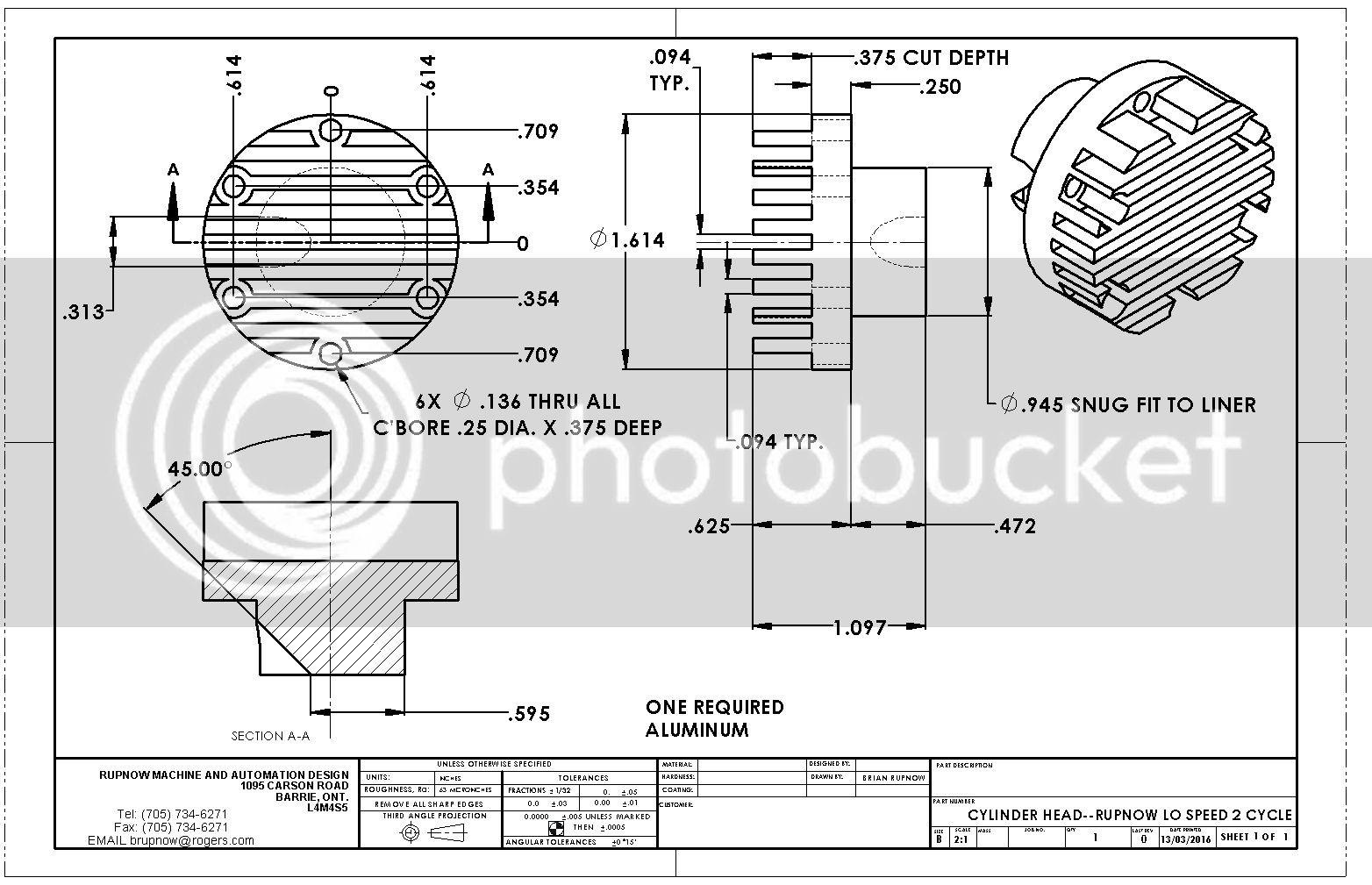

As you can see in the drawing in the last post, this cylinder head actually extends down almost half an inch into the top of the cylinder. This would completely cover the end of the sparkplug, if not for a relief machined into the side of the cylinder head in the sparkplug area. So--I made the cylinder head, bolted it upside down to the main body, and this gave me something to hold onto while the clearance was machined.


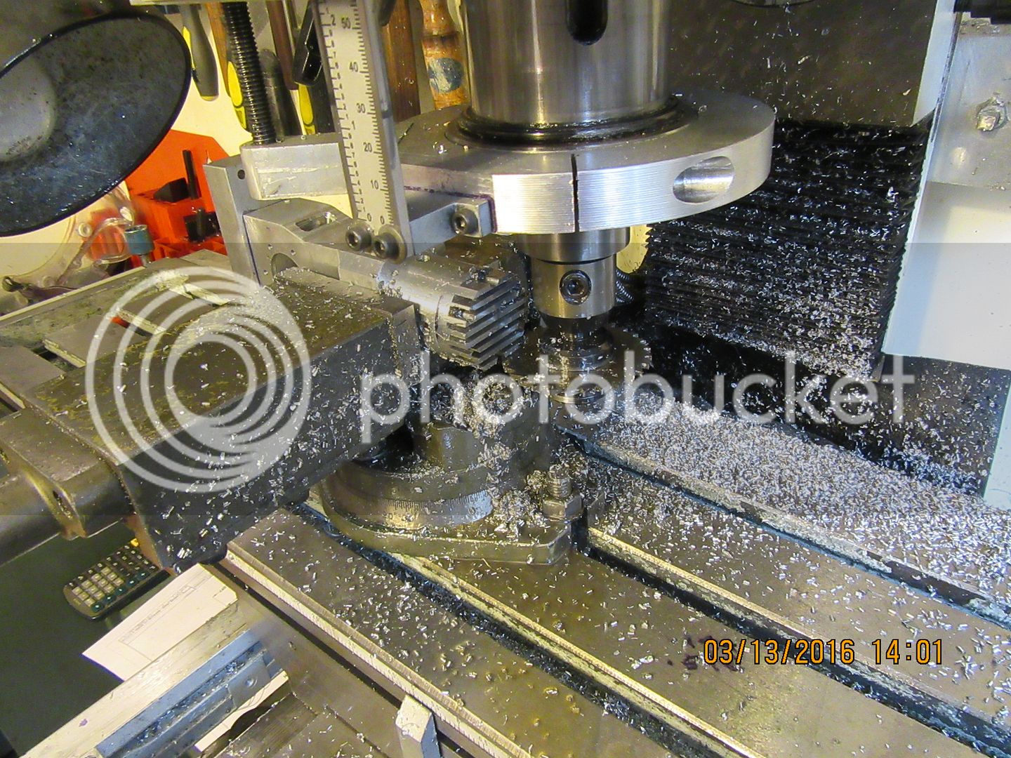
I held the main body in my milling vice with the cylinder head bolted to it, and used a 3/32" slitting saw to put the slots into the head to create "fins". Each machined slot was cut at a depth of 0.120" each pass, got 3 passes in total, and the slitting saw was 3/32" thick x 2 1/2" diameter. and the mill was turning about 320 rpm.--Lots of cutting oil.

Similar threads
- Replies
- 14
- Views
- 8K


