Old School Barstock 2 Stroke

Home Model Engine Machinist Forum

Help Support Home Model Engine Machinist Forum:

This site may earn a commission from merchant affiliate links, including eBay, Amazon, and others.
The material you are using for the crankshaft would appear to be 'bright drawn' bar.* To my mind that has neither the accuracy nor the surface finish to use as-it-comes for a respectable crankshaft. At not much extra cost or difficulty of sourcing, you should be able to get 'precision ground' mild steel bar, which I would recommend as much more suitable.

* (You call it 'cold rolled' but I think that is actually something quite different, normally meaning strip rolled into sections for things like garage door rails, office partition framing, light gauge square tube and Armco. OTOH the may be some transatlantic terminological misunderstanding.)
 
Charles--I now have 16 running engines, all using what is commonly called "cold rolled" 1018 steel in Canada and United States. I'm not sure whether I ever considered my crankshafts to be respectable or not. I know that they work, and work quite well for model engines.
 
If the male part has a rough finish, then the press fit won't be too good because of all the micro-ridges on the part (they give a rather false reading on the micrometer.)


Brian
if this is the case (parts finish) just go with a slide fit
and then knurl your male part. Those two together works
100% and for security use the green locktite on assembly

good Luck
 
Hello Brian,
Down here in the USA what you call cold rolled we refer to as cold drawn. That is what you might have obtained because it is typically dimensionally close to precision ground round stock and has a reasonable smooth surface finish.

Peter J.
 
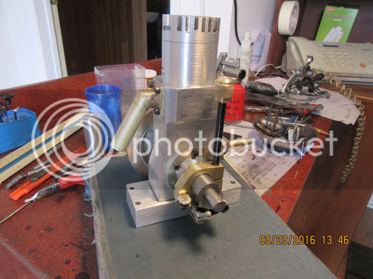
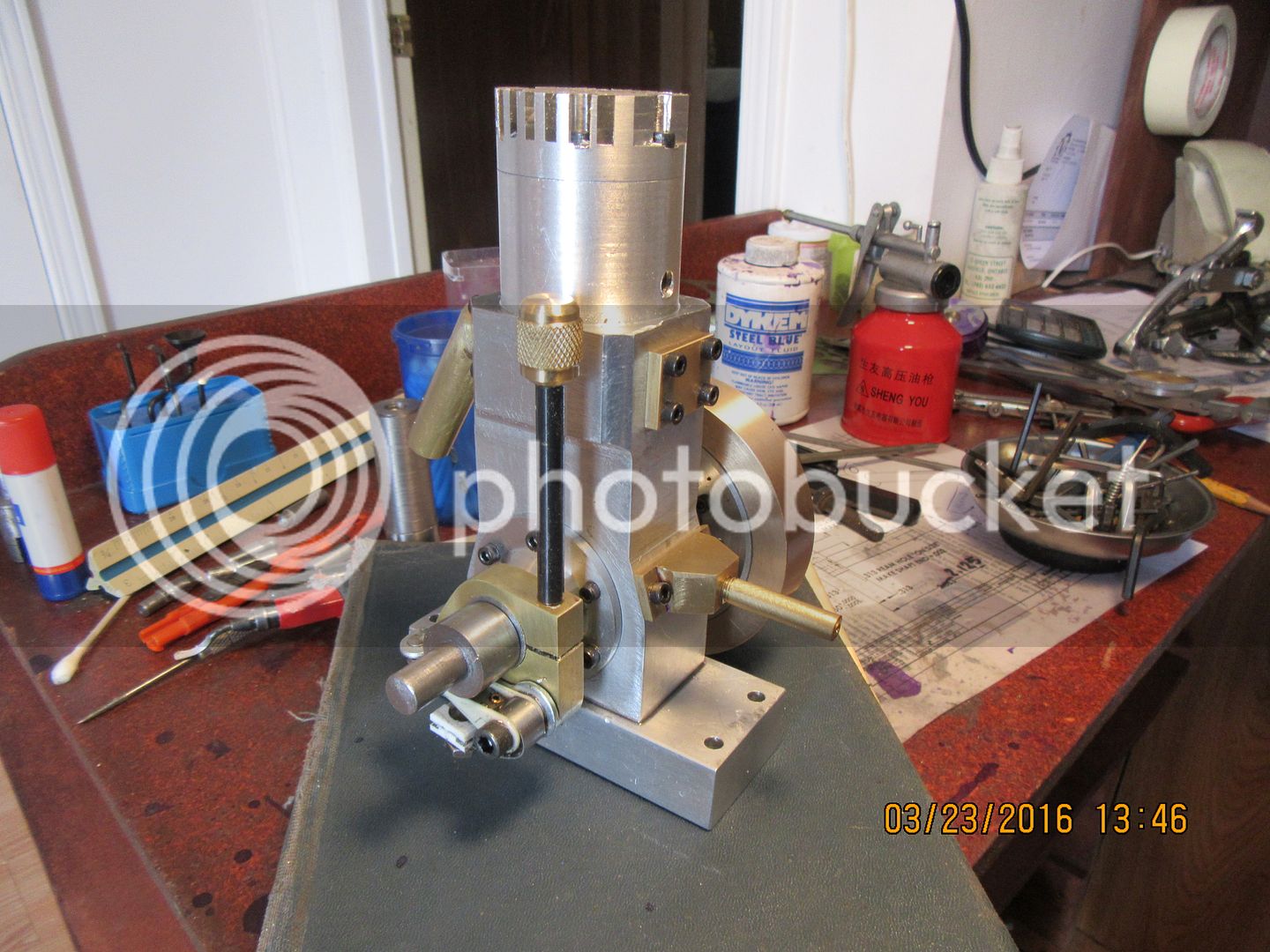
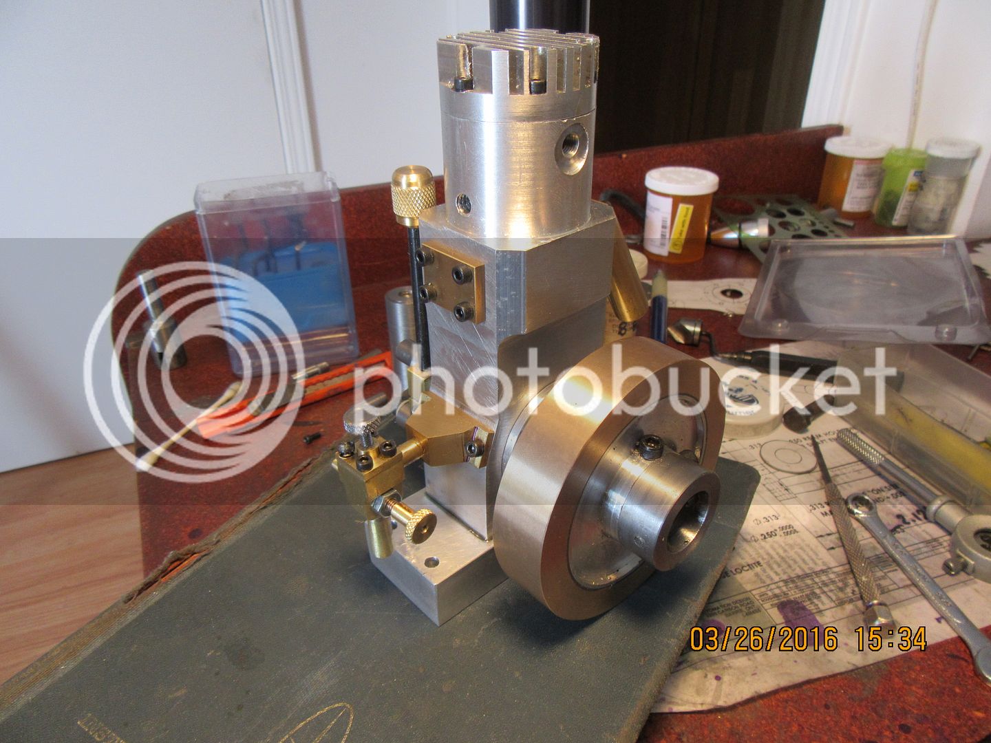
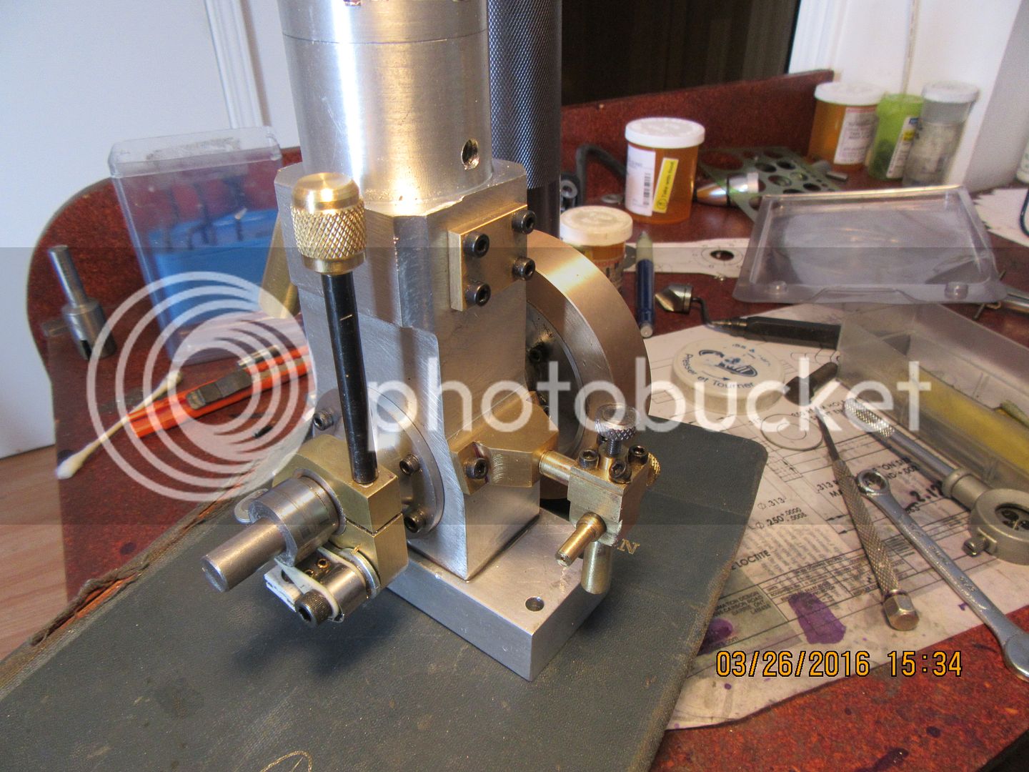
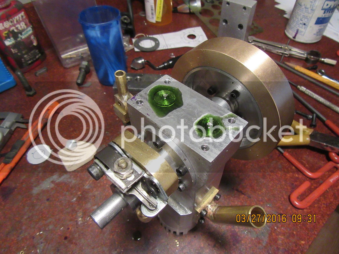
Today I made up the bracket which mounts the ignition points, along with it's handle and the ignition cam. The points bracket allows me to unscrew the handle to loosen up the grip on the end of the coned bushing housing, and lets me adjust the ignition timing while the engine is running. I still have to mill a flat on the ignition cam and put in a set screw.

 
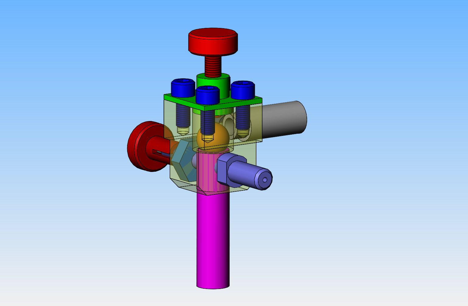
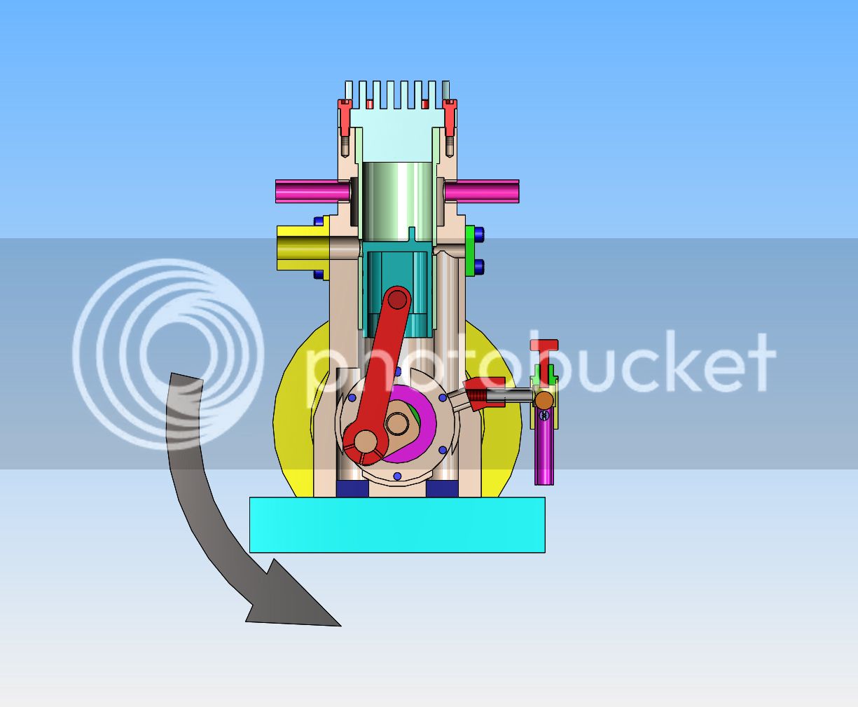
Before I start to cut any metal for the carburetor, I thought a bit of redesign was called for. From what I am able to understand of the original design, everything leading into the main carburetor body was soldered into place, with the check ball held captive in the center. That's fine, if the check ball really seals the way it is intended to. However, if the ball doesn't seat just right, there is nothing you can do about it without unsoldering pipes, which isn't a really great option. I decided that I wanted access to the ball, so I enlarged the main body enough to get four #40 socket head capscrews in there to hold the top on. I will add a gasket in there too under the top plate, but I haven't shown it in the model.
 
I've spent a large part of today doing what I call "Hold your breath machining!!"
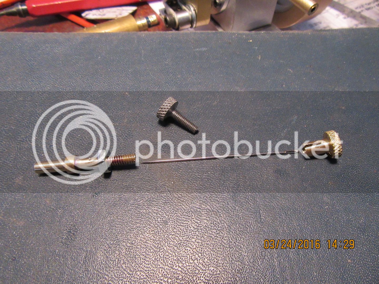
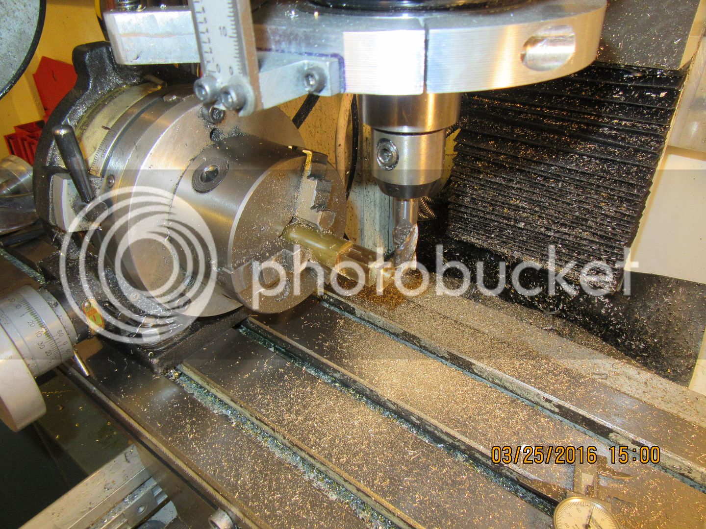
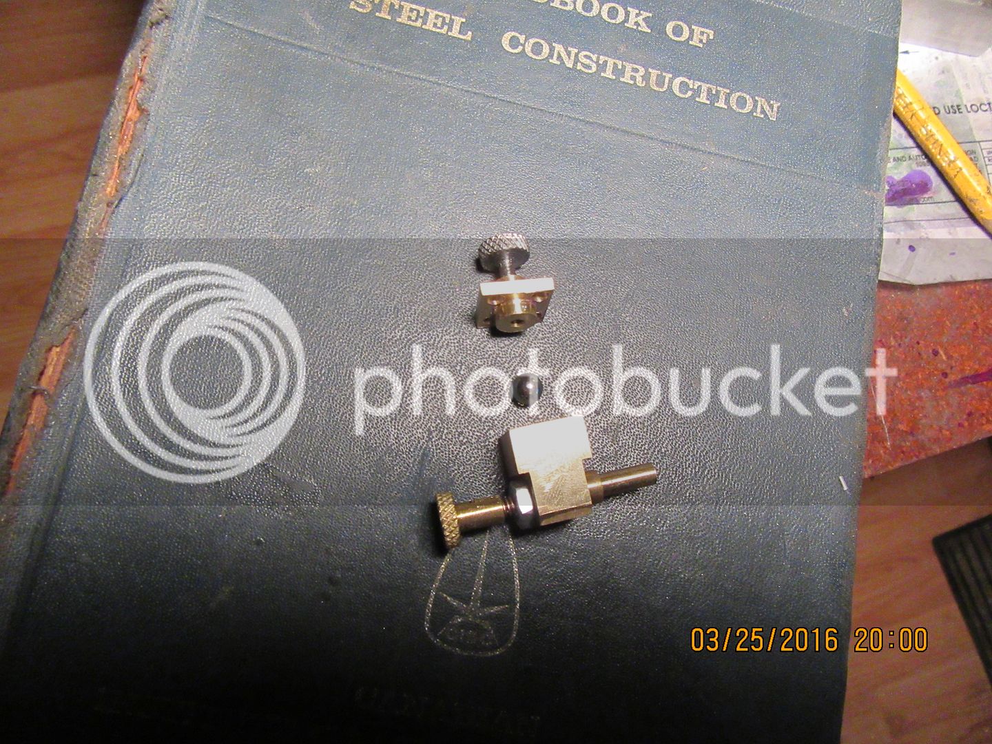
Before I make the two large parts of the carburetor (and remember, "large" is a relative thing here) I had to first see if I could make the small parts that make the carburetor work. That longest brass piece has a 1 mm (0.039") diameter hole drilled half the length of it, a 0.056" diameter hole through the remaining half, and a 1 mm cross hole drilled in it. The o.d. is threaded #6-32, and the needle valve top (the brass part with the split in it) has a 0.045" hole completely through it and a #6-32 internal thread. The needle which will become the other part of my needle valve, is a sewing needle. The steel part with the knurled top and the #5-40 thread on it is what holds the check valve down in place, and effectively becomes the throttle. Everything seems to have went okay, so the two larger parts of the carburetor will come next.
 
In the time honored tradition of "making do with what you got", this is a prime example of making round stuff into square stuff.--An added benefit is that I was able to turn the two diameters in the 3 jaw on the lathe before starting to square things up. This is going to end up being the main body and cap of the carburetor.
 
We're close.--Very, very close. It's been a long day, but I've managed to squeak out a carburetor. An hours work should see it finished.
 
You may remember from "section views" taken thru the main body, that I had to drill holes up thru the inside of the main body from the bottom to provide an air passage from the crankcase up to the intake ports, and for rod clearance at the 3:00 position. Now it is time to plug and seal these access holes in the bottom of the main body to ensure an air tight crankcase. Aluminum plugs were turned to the correct diameter, coated in Loctite, and inserted into the holes. Then the entire engine is turned upside down, and a bit more Loctite poured onto the top of the plugs and the surrounding engine base. After 24 to 48 hours, I will file the area flat and clean, and reinstall the baseplate.

 
I'm getting awfully close to "showtime" here-----If there's going to be a "showtime."!! I really don't know what to expect. I made all the gaskets today while the Loctite was drying on the plugs in the bottom, and installed them about an hour ago. The only thing remaining to be done to the engine is to apply the Loctite #574 to the liner to seal the water-cooled area and the sparkplug entrance hole, which is tapped into the aluminum housing but is a small clearance fit thru the side of the liner. I'm not going to bother doing anything with the waterpump until I know if the engine is going to run. With my usual 4 stroke engines running a Viton ring and hand lapped valves, I am always quite confident they will run---but this 2 cycle business is so new to me I don't know what to expect.The loctite is in transit from somewhere in the USA to my local Brafasco dealer and should be here this week. Keep your fingers crossed for me.---Brian
 
There may be a clue here to which way my engine will rotate. This old engine has the almost exact same physical layout as the engine I am currently building. When he starts the engine, you can see that he flips the engine counterclockwise when facing the flywheel. This of course is exactly opposite of what I was hoping for, but it's not really a big deal. the engine certainly runs nice.---EDIT EDIT--after carefully watching the entire video, I can see that when he moves the timing lever far enough in one direction, the engine slows, then kicks back and reverses direction and runs equally as well in the other direction!!-Brian
[ame]https://www.youtube.com/watch?v=1FbLzBkH4Ic&feature=player_embedded[/ame]
 
I can see that when he moves the timing lever far enough in one direction, the engine slows, then kicks back and reverses direction and runs equally as well in the other direction!!-Brian
https://www.youtube.com/watch?v=1FbLzBkH4Ic&feature=player_embedded


Hi Brian,
you can do that with your's also :)

this is how the get reverse to work on ski-doo with 2 strokes engine.

the only difference is the ski-doo have 2 ignition system,
it's easier togle the switch and you are in reverse


as you can see he stops the ignition system when changing from one side to the other
and it's done at low RPM

BTW a single cylinder diesel can be started in both Rotation also CW and CCW

enjoy
 
Last edited:
Yes Luc, I can remember back in the day, when everybody was running 12.3 Skidoo's. One of the first things to break was the starter rewind system, so people just threw the rewind away and filed a notch for the starter rope like an old Evinrude outboard. If you wound the rope wrong way round, you wouldn't know it was running backwards until you hit the throttle. More than a few teeth were lost on windshields because of that one!!
 
I had a 1908 Gray 3hp one cylinder in a boat. It had to much compression to turn through so you started it by bouncing it off compression, in the opposite way you wanted it to run. if you had the timing right it ran the way you wanted, which was nice because the prop was directly connected- there was no neutral or reverse, you were moving in the way the engine was running. It did take some learning, but actually was fairly reliable.
 
Ron---When I was a kid, I had an old Evinrude or Johnston, (can't remember which) that had dual opposed cylinders and no cowling. The sparkplug on one cylinder bank was exactly in the same spot your elbow had to be to steer the boat by turning the engine. Every time I went out in the boat, I managed to get my elbow into that sparkplug. People around the lake knew me as "That kid with the old boat motor that curses a lot!!!"
 
This morning I completed the last 3 things which had to be done to the engine. I milled a keyseat in the drive side crankshaft where the flywheel connects to it, built a small brass shim to remove excess end-play from the crankshaft, and used a small 3 cornered file to put the oil-slots partway through the crankshaft bushings. Now it's just a matter of waiting for my Loctite 574 to come in.
 
I was just told the Loctite 574 I have on order won't be in until the 7th of April. That's okay. I do need a break.
 

Latest posts

Back
Top