Old School Barstock 2 Stroke

Home Model Engine Machinist Forum

Help Support Home Model Engine Machinist Forum:

This site may earn a commission from merchant affiliate links, including eBay, Amazon, and others.
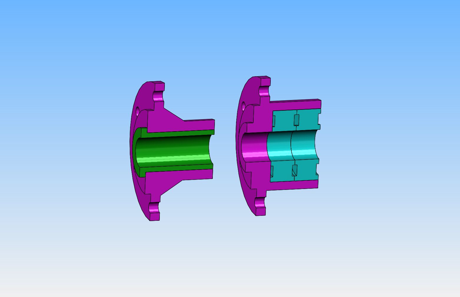
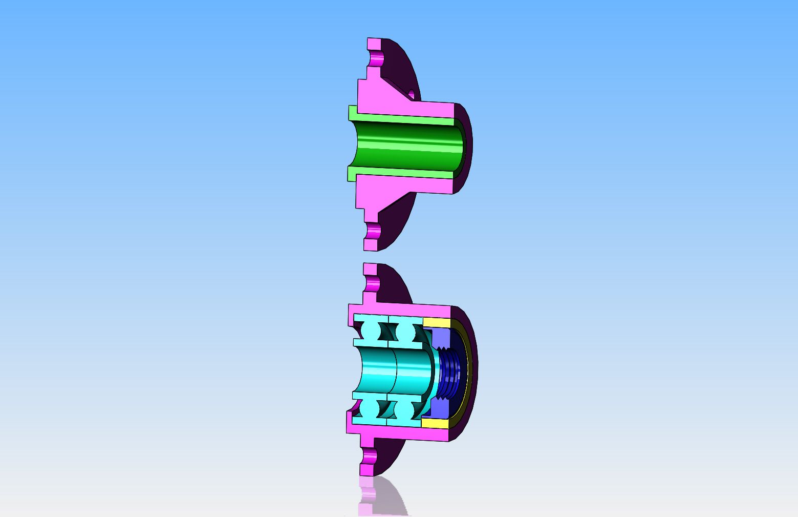
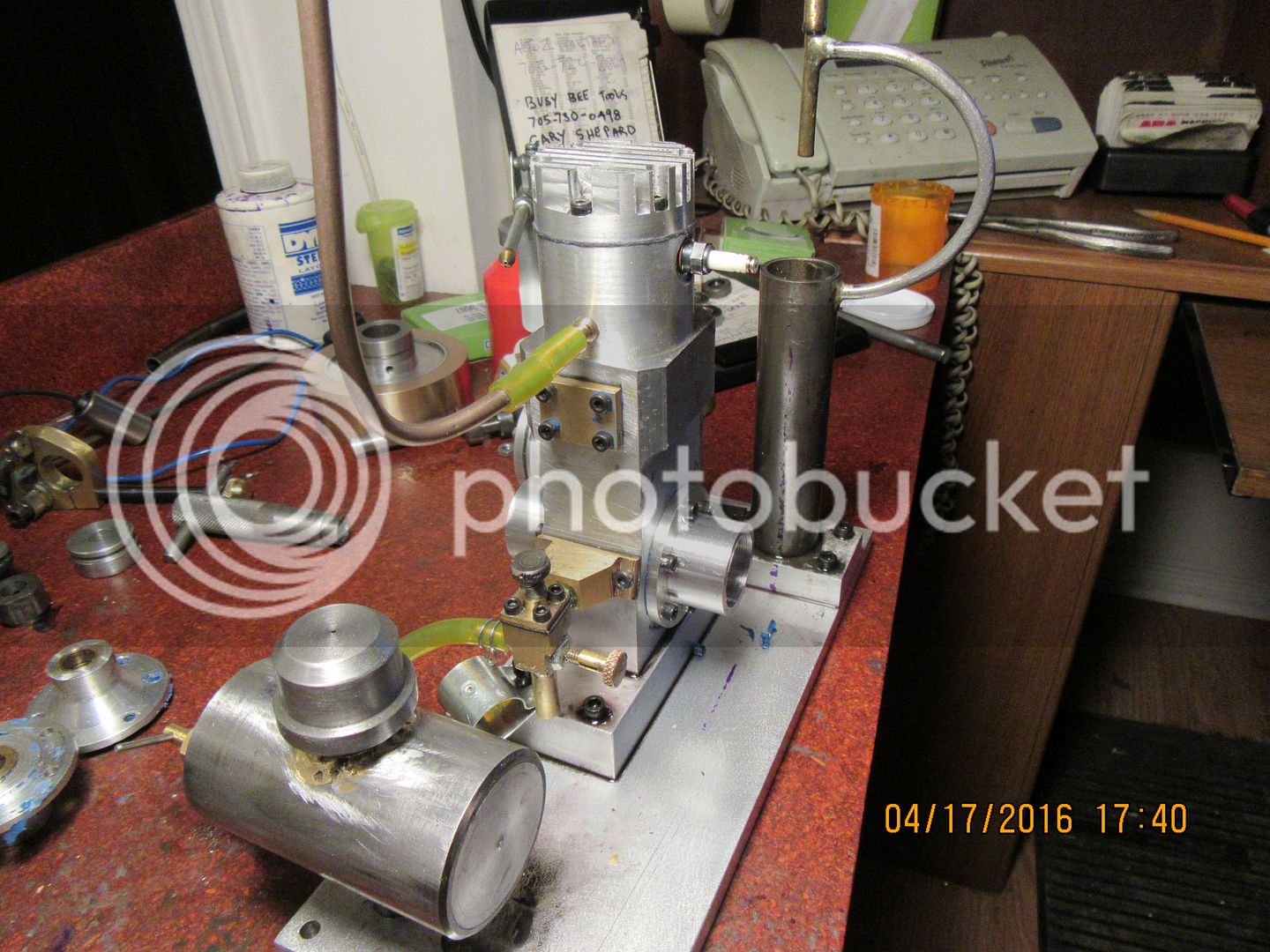
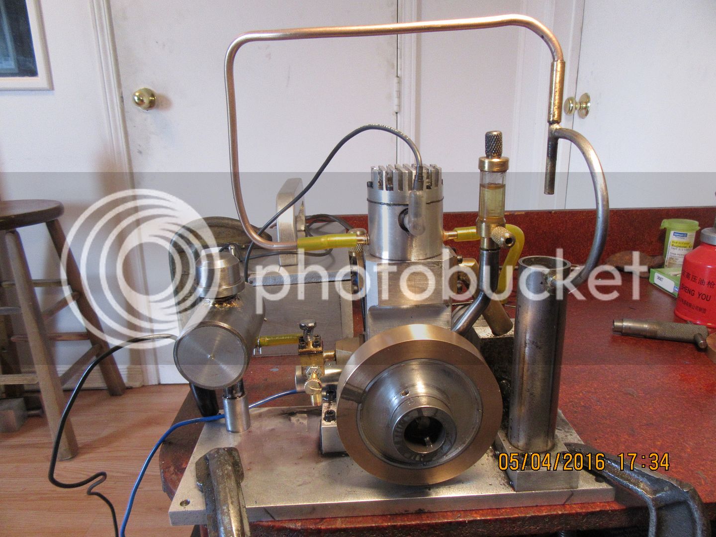
When I built this engine, my biggest concern was lapping the piston into the cylinder so that it would run without rings. This was something I had never done before, and it was a totally new learning experience for me. As far as porting is concerned, I copied a proven design, so I assumed it would run if my piston lapping experience was a success. It runs!! Hooray!!! I have ran the engine for about 3 hours now, and have discovered a flaw. When I made the bushings which the crankshaft runs in ( the green one on the left), I made them from brass. Now after 3 hours of running, the crankshaft is very loose and "wobbly" in these bushings. This means that no doubt the crankcase is sucking air thru the clearance around the crankshaft. I know that it is blowing oil out around the crankshaft, because I have the tracks on my desktop on both sides of the engine to prove it. My goal was to not only have a running engine, but to have an engine which would operate at a much lower rpm than this engine is capable of. The lowest sustainable speed I have been able to achieve is about 850 to 900 rpm, and the longer I've ran the engine, the faster it needs to run to keep from stalling. This is a sure sign of leaking air around the crankshaft. Today I went to Canadian Bearings and after searching thru their bearing catalogue, I discovered that a #1610 ball bearing was 3/8" i.d. x .910" o.d. x .312" thick. I also discovered that they have triple lip rubber shaft seals that are 3/8" i.d. x 3/4" o.d. x unknown thickness. I ordered 4 bearings and two shaft seals, which cost a total of $49.00. I will make two new bearing housings, which will each get two ball bearings and one seal (which I haven't shown yet). My design on the right is not complete yet, because #1--I don't know the thickness of the seals yet, and #2 --the bearings are sealed units, and depending on the old "blow your guts out" test may not even require the use of a separate shaft seal. Each bearing housing needs two bearings because of the fact that the crankshaft is a "two-piece" configuration and will not act as a 'bridge" to allow use of one bearing in each housing. I will keep you posted as things develop.----Brian
 
Ron--I have already tried the heavier flywheel route. It helps, but it only helps some. Luckily, there was enough room between the existing flywheel and the side of the main aluminum body that I was able to add 3/8 inches more of brass to the side of the existing flywheel, which increases the flywheel mass by about 50%---Brian
 
Last edited:
This is getting very interesting indeed. I picked up my bearings and seals today, and was able to create a 3D model of the seal. The outer diameter of the 3/8" shaft seal is 3/4", which means that I will have to machine an adapter ring (yellow) to mount the seal. I will remove the seals from the bearings so they get their lubrication from the 2 cycle oil mixed with the fuel. I can make new housings the same length as the existing housings which means that I won't have to modify my crankshaft, and they should bolt right onto the main engine housing.
 
Last edited:
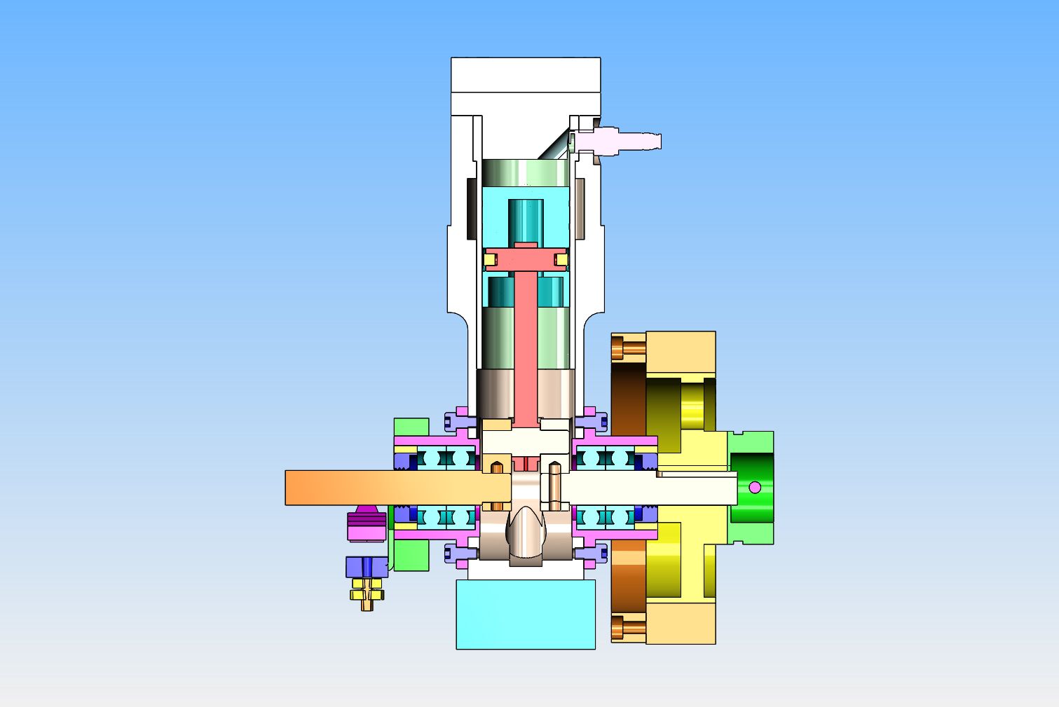
And just for the fun of it, here is a cross section thru the engine----Nothing has been changed except that the coned bushing housings and bushings have been exchanged for the new housings with ball bearings and seals. I also show the 3/8" wide addition I made to the side of the flywheel to give it a bit more weight.-----I will have to make a new ignition points mounting bracket.
 
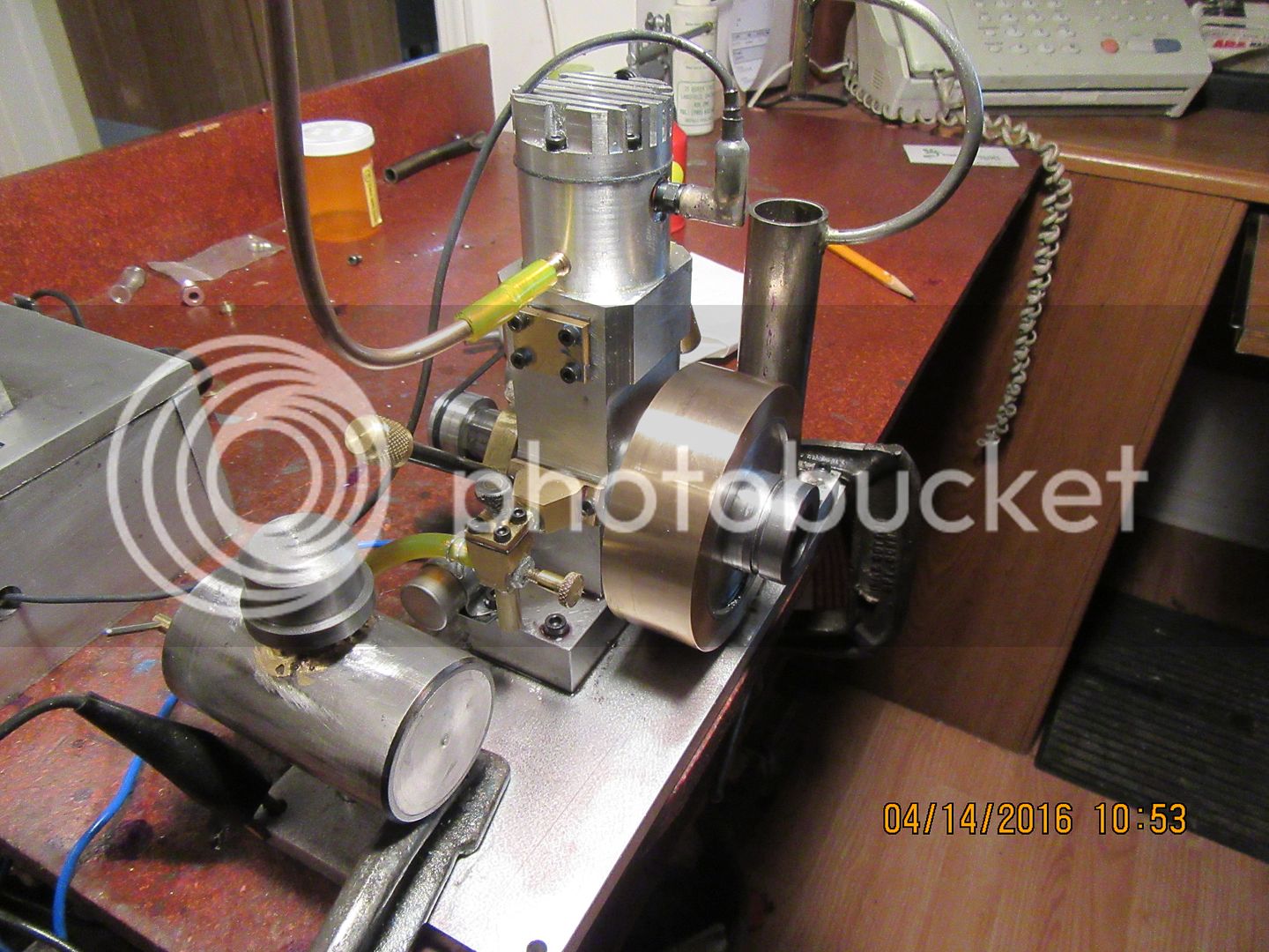
The new bearing housings are finished and trial fitted in this picture. I use ordinate measurements for all my hole patterns using the DRO's on my mill. and things always seem to fit, but it still seems a bit like black magic to me. i always trial fit things just to be really sure they fit together properly before final assembly. I am having second thoughts about removing the seals from the bearings. They don't seem that stiff to me, even when they are brand new, and they will certainly loosen up with a few thousand revolutions on them. I will hopefully stick everything back together tomorrow and see what happens.
 
As things keep moving moving ahead I keep adding to my own knowledge base. I ended up leaving the grease seals in the ball bearings, and installing a plain 3/8" dummy crankshaft in the engine with a 3" v-pulley on it and driving it for an hour with an 1800 rpm electric motor just to remove any "new bearing seal stiction" . What I have discovered is that after an hours running, the bearings with grease seals rotate very freely. However---the separate shaft seals, even though they have only a thin rubber lip in contact with the shaft add a surprising amount of "stiction". (rolling friction) to the shaft. I am going to try these assemblies in the engine to see what happens. I know they won't leak any crankcase compression or suction. If they add too much stiffness to the rotating crankshaft, I will simply take an exacto knife and cut the lip out of the shaft seals.
 
Okay, one final post to finish off this thread. I had to raise the gas tank back up 1" to get the engine to run successfully. (I had lowered it about 1" previously). The engine will clip way all day quite comfortably at the speed shown, but really isn't too crazy about running faster or slower. That carburetor is pretty hokey, but it gets the job done. The speed control screw on top of the carburetor does have some effect, but with an engine this small it is only about half a turn from the speed shown to a speed lower than the engine will run, and consequently stalls out. I did end up making the flywheel about 3/8" wider than the original plans call for. I am going to say this thread is well and truly finished now, and that I have successfully built and ran my first two cycle engine. This is the first i.c. engine I have ever made with no rings, where the piston was lapped into the cylinder with diamond lapping paste for an air tight fit. With each engine I build I learn some new skill, and that pleases me a great deal.----Brian
[ame]https://www.youtube.com/watch?v=4Agy4Lf97-I&feature=youtu.be[/ame]
 
Sounds great Brian, like it's making lots of power and I'm surprised it doesn't want to rev. Still, I'm sure you'll find something for it to drive that uses up all that available power.
 
After running the engine for about 20 minutes with the new ball bearings, I noticed that the flywheel was beginning to wobble. I shut the motor off, and sure enough, the crankshaft end with the flywheel on it was quite "wobbly" in the bearings. If I hadn't seen it myself, I would have said that was impossible. They were good quality name brand ball bearings, but after the grease shields wore in a bit, there was enough clearance in the bearings that with two bearings setting side by side like I had them, they allowed the shaft to wobble quite noticeably. So----I took a page from Jason's book. I had already determined on my first go-round with this engine that brass was simply too soft a material for a bushing, as the brass bushings wore out very rapidly. I don't know if this had anything to do with lack of lubrication or not, although I doubt it. So---this time on the crankshaft side only, I made up a new aluminum housing with an insert of 7/8" diameter #660 bronze, which I bored .001" undersize, then lapped the crankshaft into it with #600 carborundum paste. I added an oiler that I had made way back when I built my Kerzel engine, and a steel tube which supports the oiler and runs to the center of the bronze bushing. Time will tell if this was a good idea or not!!
 
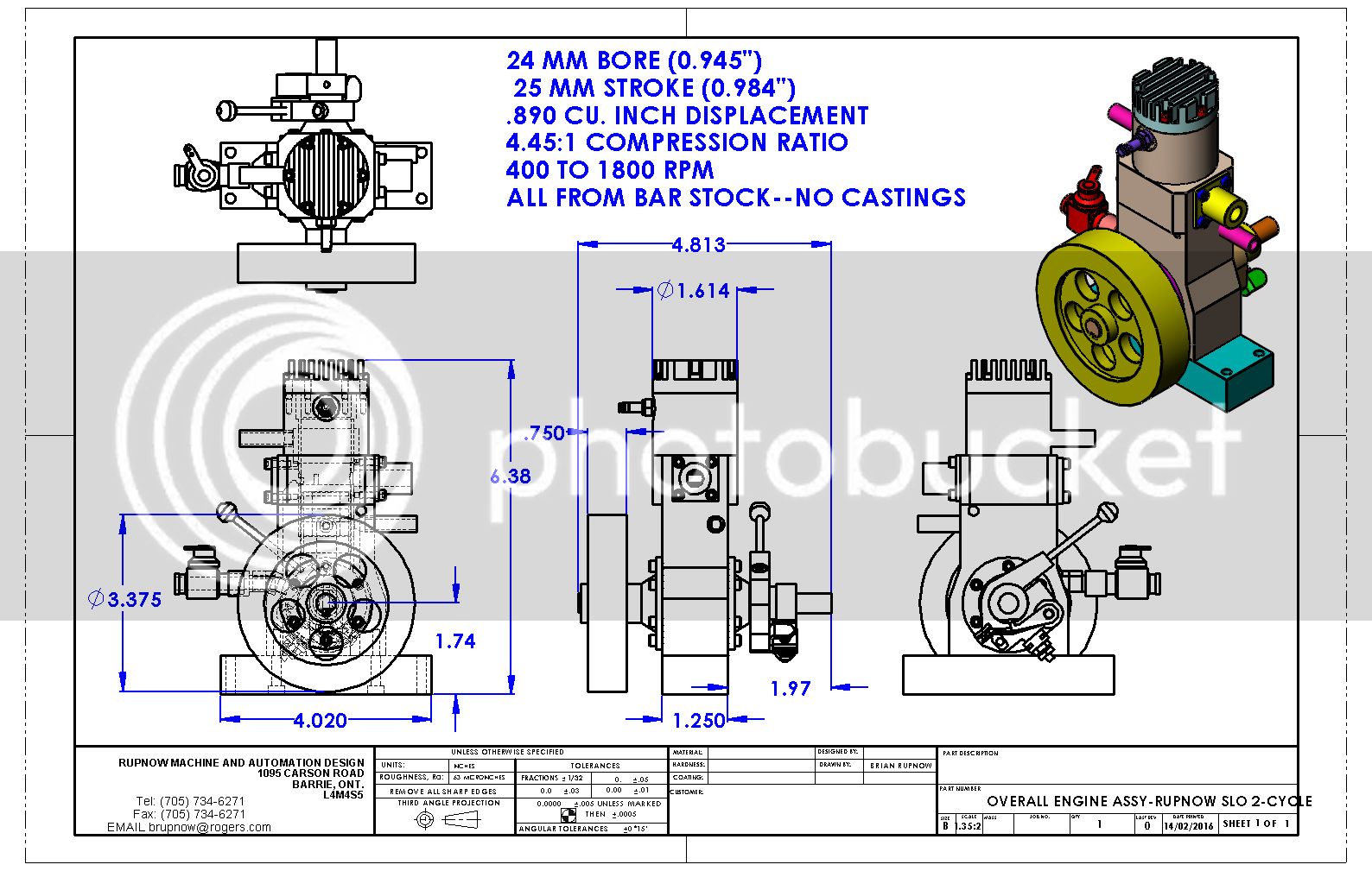
This shows the overall dimensions of the engine. I will be posting the detail drawings as I make the individual parts. I will not post them before making the parts, because I have found that quite often the machinist at my house has to go back and remind the engineer at my house that "You can't make it this way!!!---Change the damned drawing please!!!
Hello Brian,
My name is Roger; I live in France.
I am interested in manufacturing this engine. Where can I buy the plan? Thanks for your help.
 
Model engines always run fast. Its part of the problem that you cannot scale physics. The flywheels are just to small. Maybe you could make one from depleted uranium to get more weight? :)
Check with 'ol Doc Brown,he may have some left from the Delorean,lol.
 
You also need to scale time. Do this by considering the period of a pendulum. If a model is, say, 1/8 scale, time should pass about 2.8 times faster. Or, to put it another way, if your engine is 1/8 scale, 950 rpm represents a full-scale speed of about 340 rpm.
 
Hi Brian,
I'm surprised you lapped the crankshaft into a bronze sleeve. I was told that if you did this,the carborundum paste would embed itself into the Bronze making itself into a lap permanently, thereby wearing the crankshaft in no time.
Of course as always I stand to be corrected.
Good engine though and well documented.
All the best
 
Roger--Do you have any kind of 3D cad software? If you have Solidworks, I can give you all the drawings and solid models. This engine was not one of the engines I intended to sell plans for, so the drawings were never saved as pdf files.---Brian
 
Back
Top