Briggs & Stratton 6S - A Beginnig

Home Model Engine Machinist Forum

Help Support Home Model Engine Machinist Forum:

This site may earn a commission from merchant affiliate links, including eBay, Amazon, and others.
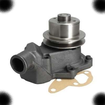
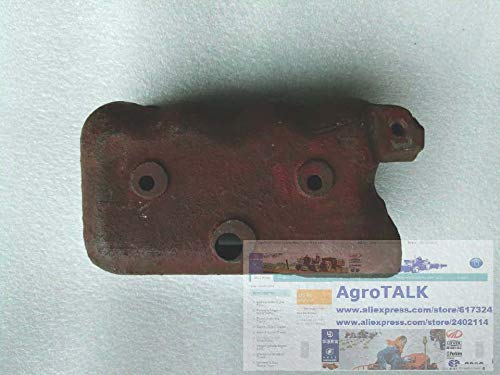
More work yesterday on the crank...back to the lathe to bring the crankpin closer to the needed .375" diameter with some gradual and careful filing and smoothing with 400 grit paper. Once it was close I used the DTI to check for roundness (photo 1) and a bit surprisingly I found a couple of high spots. With the lathe off I used the 400 grit paper just on the high spots (similar to buffing the toe of a shoe during a shoeshine) and kept rechecking until the pin was round to within about .0005" (photo2). Then the conrod was fit around it and checked for a nice running fit. There were still a couple of binding points (due to the bore of the conrod rather than the pin, so I worked put a dab of "very fine clover compound in the conrod bore, reassembled it and worked it round and round (not under power) until things leveled out (photo 3). After cleaning, oiling and reassembling again the fit seems as close as I am able to get it. This area should get more than enough lubrication under running conditions. With that step done I could finallly part of the crank web and go back to the 3 jaw chuck to bring the whole thing down to the required width and then turn the bearing surfaces on either end as shown in the final picture. Today I will work more on the webs, forming the counterbalance portions opposite the crankpin and narrowing the arms from the pin down to where the counterbalance portion begins. Hope to have more progress to show later.


IMG_0363.JPG


IMG_0364.JPG


IMG_0360.JPG


IMG_0365.JPG
 
Sorry I haven't been keeping up as much as I'd like to.

I like the nameplate. I've thought about what I'd do for that once I get around to making bases or feeling proud enough of my work. No laser printer here so at some point I'll have to investigate alternatives.

Your base looks good too. Well...everything looks good. You do real good work.
 
Thanks Zee...I have been following your Spinster project too and enjoying that. I'm glad things are back to a more normal situation in your shop too.

Bill
 
More great progress, Bill. Seeing the con-rod on the crank, it looks so 'full sized'. Such a good build.
 
Love the pictures of the crank on the Sherline Bill. Amazing what those little machines can do.

Steve
 
Thanks Dean and Steve. I spent all afternoon and evening in the shop dead set on getting the crankshaft done and I am there except for pinning it together and some bead blasting on the crank to blend out some machining, filing and burr grinfing marks and to make it look more like a casting which the original definitely is. The four pictures in this post show the steps for thinning the crank arms, further reducing their width under the bearing surfaces on each end and finally reducing their side to side thickness... hopefully the pictures make it clearer than my poor description.

IMG_0366.JPG


IMG_0367.JPG


IMG_0368.JPG


IMG_0369.JPG
 
Next came the assembly and putting in the two separate shafts that had been made previously. Not much here to describe so I'll just show the resulrs along with the prototype crankshaft.


IMG_0372.JPG


IMG_0373.JPG


IMG_0374.JPG


IMG_0375.JPG
 
pretty neat!

I will be spending some time reading this thread tonite, it's been a while since I last followed it...

A fellow sherliner, I see?

take care,

tom in MA
 
Thanks for looking in again Tom. Lastly for tonight, I wanted to see that the whole thing would look like with the piston and con rod attached. Again no description necessary. This part is one of the one's I was most worried about reproducing faithfully to the original, and its not a perfect match but i think it does have much of the same character as the prototype so all in all i am happy with and happy to be done with it.

IMG_0376.JPG


IMG_0377.JPG


IMG_0378.JPG
 
Bill, I haven't jumped in here until now. First, all I can say is "WOW!" Excellent craftsmanship on the little B&S. :bow:

Secondly, I have sat here this evening for the last hour going over this entire thread and want to say thanks for bringing us along on the journey. Threads like this are an inspiration to me many of us on this board. So, thanks for taking the time to document the progress.

I have a small engine project I started quite a while back, and life worked its way between me and the ability to finish it up. Time is a precious commodity, and I have had very little of it during the past couple of years. As soon as I finish typing this reply, I am off to the man cave to see exactly where I left off. Who knows, there might be a few chips flying this evening!

Best regards,
Casey
 
Wareagle, thanks so mich for the kind words and for taking YOUR time to go through the thread. As you can tell, this project has had a more than a few starts and stops as well...so I know how much of a premium time for hobbies can be at times, So here's to making more chips and more time in the man cave... and I look forward to seeing what you've been up to also.

Regards,
Bill
 
Bill, your new pics for today... Wow. Like Casey said, inspirational, and in so many ways.
I follow a number of threads and read the forum every day. I don't get to post as much lately, simply from being well and happily busy. I always try to hit this thread, though, and watch for new postings here.
I expect the finished engine to be as extraordinary as your work here, and I'm sure it will be!

The crank, rod, and piston all together for their family shot is great!

Dean
 
Just echoing what Dean said, it's a work of art just like the rest of the engine. You'll need to make another though to display next to it as it's such a shame that won't be seen tucked away inside the crankcase! :big:

Nick
 
Beautiful craftsmanship Bill! :bow

Rick
 
Dean, Nick, and Rick...thanks for the kind words. Never one to leave things alone, before bead blasting the crank today I decided that the upper end of the crank arms near the crankpin needed to be rounded more like the prototype which was done on the belt sander at work...its a better match now as shown in the photo compared to those i posted yesterday, I have to order the taper pins and reamer but will lay this aside now and get back to the crankcase which is the last major part...hard to believe. That light at the end of the tunnel is getting brighter.

IMG_0385.JPG
 
Thanks Nick....I think.... :big:
 
One thing left to do on the flywheel was to taper its bore to match that of the crankshaft. After missing the mark while trying to do this on the flywheel itself, I bored it out to .500 and remachine a bushing instead which was Loctited into the flywheel. This is probably how it should have been done in the first place but time will tell. The set-up for machining the bushing taper is shown in photo 1. In order for the two taper to fit as closely as possible the crankshafe was mounted in the lathe chuck and the flywheel held against it. Several applications of some very fine Clover compound with cleaning in between each seemed to seat the tapers well with little to no wobble in the flysheel (photo 2). The last two pictures are of the crankshaft in position through the mounting plate which holds the oilite bushing that supports the flywheel side of the crankshaft. An identical bushing will be mounted in the crankcase to support the other side of the crankshaft.

IMG_0386.JPG


IMG_0389.JPG


IMG_0390.JPG


IMG_0391.JPG
 
The next pictures are still of the whole sub-assembly..it was just too tempting to see how it was all going to fit together. The 6/0 taper pins and reamer arrived so today i hope to get the crankshaft all pinned together but more on that later.

Thanks for having a look.

IMG_0392.JPG


IMG_0394.JPG


IMG_0396.JPG


IMG_0397.JPG
 

Latest posts

Back
Top