Briggs & Stratton 6S - A Beginnig

Home Model Engine Machinist Forum

Help Support Home Model Engine Machinist Forum:

This site may earn a commission from merchant affiliate links, including eBay, Amazon, and others.
Nice.
Interesting too. Even though my experience is pretty limited...I don't see setups like that very often. Always amazes me what people can do.
 
That's an interesting piece for a roundy-round thingy. I'll have to wait until you put it in the engine
to see what you described. Lot of work in it! Nicely done, as always, Bill.

Dean
 
Thanks Zee and Dean,

I know the description is hard to follow, I will post a pic of the full size one tonight, where it's located and how it fits into the crankcase...just didn't have them handy when these photos were taken.

Bill
 
Here is a photo of the full size crankcase and the back of the cover plate. The bushing holder/oil catcher piece in my last post will be a slip fit into the large opening on the side of the crankcase, just as it is in the prototype. I hope this clarifies my rather poor word description earlier...something about a picture being worth a thousand words ;D


Cover_Plate_Back 001.jpg
 
Bill, that last "thingy" you made is a seriously neat piece of work :bow:

How did you set your RT to the angle ? - I'm very curious, as some ideas I have in mind will also require a setup like that. So far, the best idea that's popped into my head is to make a swivel plate to do it...

Regards, Arnold
 
Arnold,
It doesn't show well in the pictures so hopefully those below will show it better. The RT is mounted to an angle plate which I got from Sherline as shown in photo 1. It comes with a 3/4-16 adapter so that the lathe chuck can be screwed directly to it. It also comes predrilled with the hold down patterns for the RT and the mill vise with or without its rotating base. The RT is shown in the second photo similar to the way it was set up for making this "thingy" part. Certainly you could make an angle plate or buy others on the market but one of the things I appreciate most about Sherline is the integration of all of the accessories. In this case I could turn the diameter of the part on the lathe, mill out the pockets between the ribs and angle cut two of the three ribs without ever having to remove the stock from the chuck. That can be a huge advantage at times when concentricity must be maintained and when you don't wish to re-indicate a part in the lathe chuck for further operations.

Hope this answers your question.

IMG_0158.JPG


IMG_0159.JPG
 
Thanks for the extra pic, Bill. Wasn't your word description. I just have a hard time visualizing at times.
Sometimes, I just need to see a thing to make it come to life. Sometimes, gotta lay hands on it!

Dean
 
Thanks very much for the explanation and the extra photo Bill :) - MUCH appreciated!

Another tooling project for my long "to build list" then :big:

Kind regards, Arnold
 
Its been way too hot in the garage to spend much time there but a few little odds and ends got done. The bushing holder got parted off and finished to the correct length, the mounting studs to attach the breaker/condenser cover to the plate were made and installed and these parts were trial fitted as shown below. I got the bushings ordered on Friday from McMaster, and the shaft seals ordered from Allied which was recommended a page or so back. I was surprised they accepted such a small order but so far so good. The bushings should arrive early in the week so the final boring of the holder and the bolster in the plate can be finished and these parts permanently attached. Between sweat sessions more drawing got done, thankfully inside in the AC Thats about it for now.

IMG_0160.JPG


IMG_0161.JPG


IMG_0162.JPG
 
Here are the front and back shots of the prototype and model. There are still a few details left on the model but nothing too tedious, Thanks for checking in.

IMG_0163.JPG


IMG_0164.JPG
 
The bushings arrived Tuesday which allowed finishing uo the hole in the plate (photo 1) and the bushing holder (photos 2 & 3). Since the close fit of the bushing holder OD into the side of the crankcase will maintain alignment of the bushing, it was critical that the OD and bore for the bushing be concentric, hence the 4 jaw was used to center the slightly undersized ID to within .001 total runout vefore enlarging it to the correct OD of the bushing. Is that confusing enough? Mayve the pictures will help. The third picture shows the bushing pressed into the holder.

IMG_0165.JPG


IMG_0171.JPG


IMG_0172.JPG
 
With this done, some of the other detail work could be completed on the plate. Photo 1 shows the drillking of one of the two bolsters that will provide the anchors for holding the flywheel cover (shroud) onto the plate assembly.

Photo 2 shows the rather unusual setup used to mill the angle on the upper back side of the plate per the prototype which will direct the airflow to the fins on the upper part of the crankcase.

Photo 3 shows drilling the bushing holder through to the ID of the bushing. Since this part of the holder will be on the inside of the crankcase, the hole will allow some of the splash oil to seep into the bushing ID and lubricate the crankshaft as it runs in the bushing.

Photo 4 shows this in closer detail.


IMG_0174.JPG


IMG_0175.JPG


IMG_0176.JPG


IMG_0181.JPG
 
The bushing extends 1/8" beyond the flat side of the holder and mates with the bore in the plate to locate the holder relative to the plate. Once these two parts were assembled and the holder oriented with the oil hole to the top, three clearance holes were drilled through the plate and bushing holder for 2-56 SHCS's secured with nuts on the opposite side. This is shown in photos 1 & 2. Photo 2 also shows the bushing extending the 1/8" into the bore on the plate. The remaining portion of the bore in the plate will hold the lips seal when these arrive.

Photos 3 & 4 show the front (outer) face of the plate assembly and the back (inner) face with bushing holder attached.


IMG_0177.JPG


IMG_0178.JPG


IMG_0179.JPG


IMG_0180.JPG
 
First rate workmanship (again), Bill. Thanks for the continuing write-up, and
the new batch of pics. This is one of my favorite builds here!

Dean
 
Thanks Dean. Things have come to the point where its going to be necessary to start in on the crankcase and crankshaft, so some of these various parts will have something to hang on to or off of or whatever.

As a side note I fiddled around with the two old 6S's I picked up at the swap meet a few months back. I swapped a few parts around to get the semi-running one configured most like the one I am modeling from, picked the best gas tank of the two and cleaned it out well, swapped the suction tube to one with a cleaner filter screen, and changed the air filter to the style of the modeled one, drained the oil and refilled the sump then gave it a go.

One thing I didn't have was a proper pull cord so i used the one I had made for the model which worked...kinda....for a while anyway.

The end result was that I did get it to run, so I now have a running 6S albeit a composite of parts from three engines. Now it needs a good clean up and a new paint job and a half scale model to sit beside it.

I may hit up Lowes this morning and see if I can find some larger cord for the pull start.

Thanks to all who are following the build...and a Happy 4th of July too!!

Bill
 
Most of the long weekend was spent getting the grime off the full size Briggs engine and starting to paint some of the parts. All I needed and didn't have was a new length of spark plug wire and a new muffler. Left work early today to run by a local lawn mower repair shop I remembered from 8-10 years back...wasn't even sure they were still in business, but sure enough there they were. Interesting visit to say the least....98 degrees today and not an air conditioned in sight. The garage area was filled to the gills with various lawn mowers, etc. and the front office looked like a tornado had gone through it. I did manage to step over a few boxes to get to a display that had a few air filters and such for more current Briggs engines, but also 5 or 6 mufflers just like I was looking for. The bubble pack on the card had so much dust on it the muffler looked almost a brass color. Actually it was painted with gray primer as i found out. So i asked the guy at the counter if they had any spark plug wire with "real" wire inside and he said he didn't think so, but one of the other guys mentioned he thought there was a spool of it on a bottom shelf. Climbing over a few boxes himself, sure enough he found it under some more dust, so I got 2 feet for $2.00 a foot which seemed reasonable. The muffler wasn't priced and he couldn't find a price in the compiter burried under reams of ancient paperwork but one of them seemed to have a smudged price of $6.25 which worked for him so I figured that was fair enough. Add to that a package of 3 flywheel keys for $2.99 and I got out for under $15.00...all in all a good afternoon's work. You gotta love old places like this...they have what you need if they can only find it.

Anyway the painting is nearly complete, so reassembly can continue tomorrow, then back to the model!

Bill
 
Hummm.
Did they happen to have any old Briggs engines laying around?

If you have a spark, enough compression to to blow your thumb off the spark plug
hole and a clean carb, don't be surprised if that old 6S starts up on the second or
third pull. They're tough old engines.

Shutting it down is the fun part. Pushing that grounded metal tab against the top
of the spark plug works fine if you don't flinch. If you don't make positive contact
it will light up your life! :D

Those old magnetos can throw lightning!

This was a Briggs 5S magneto test. The crankshaft was being turned with a
cordless hand drill set at screw driving speed.

[ame]http://www.youtube.com/watch?v=A5XMncDe924[/ame]

I use the toe of my well insulated running shoe to push that kill tab. ;)

Rick
 
Rick,
I didn't see any, but only got a glance back into the workshop area. I suspect with enough time one could uncover all sorts of things there :big:

I think I started off this thread or a related one with the still vivid memory of being "lit up" when I got my granddad's mower started (actually it looked a lot like that eclipse that you posted several pages back) and then didn't know how to stop it correctly at least.Funny how that has now come full circle some 50 years later. I am looking forward to getting this restored one running well again. Can I ask what you usually mount them on for display/running purposes? I was thinking of maybe a skid or something. Also if it is to be run at times, does it need some kind of load? Maybe something like a small squirrel cage fan?

Bill
 
My display platforms were based on what I expected the auction prices to bring.

The Briggs 5S was much more common than your 6S so it got a simple oak skid.

5S20Recoil20Display.jpg


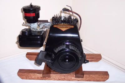
Then I got my hands on a 1940 Briggs WMB Washing Machine Engine.
It was a little rough when I got it.

WMB%20Before1.jpg


I knew it would go for a good bit more than the 5S when fully restored, so I
put a little more effort into it's display stand. Brass plaque and all! ::)
The oak to build the base cost more than all of the parts required for
the restoration, but I got that money back and more.

100_0540a.jpg


The engines don't really need a load to run well. They will purr along
nicely without having to work. I figure they've earned an easy living for
surviving this long.

There I go hijacking your thread again.

I AM loving seeing an old Briggs engine being modeled.
Amazing work! :bow:

Rick
 
Bill

Still following along and much enjoying your thread, notwithstanding the guilt you are laying on me... there's a 1953 5S hiding under my workbench patiently waiting for me to get off my duff and pay it some attention!

Looking forward to your next installment.

Cheers, Joe
 
Back
Top