Vertical I.C. Rupnow Engine

Home Model Engine Machinist Forum

Help Support Home Model Engine Machinist Forum:

This site may earn a commission from merchant affiliate links, including eBay, Amazon, and others.
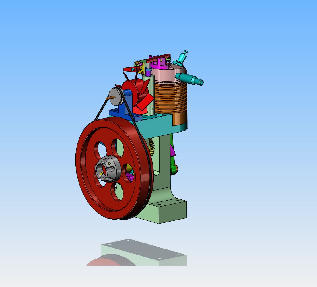
I'm still making some progress. So far I have the flywheel, crank web and big end, con-rod, con-rod retainer, rocker arm and exhaust pipe completed. Plus half the carby. Still got a long way to go and my available shop time is about to dry up. Hoping to average a completed part per week until it's all done.

I found a tiny error on the carby body plans - the throttle stop screw hole is dimensioned as .294 deep, but then threaded 4-40 .394 deep. I have to ask - what does JAG stand for?

The throttle stop hole breaks thru into the center hole that the throttle barrel fits into. You have to run your tap in at least 0394" to get past the taper on the tap.--Actually I just made that up!! The thread call outs are all an automatic function of the software. Occasionally they do something weird like that. Thank you for the update.--Brian
 
I forgot about the starter hub and push rod guide as well - I knew it felt like I'd made more parts than that...plus 2 extra con-rods and the flywheel being 3 pieces, feels like I'm halfway there. Here's a pic of my progress (minus the carb).

IMG_0180.JPG
 
Cogsy--Great stuff!!! I'm setting here with a totally dismantled computer cooling fan with a 2.2" diameter blade diameter, trying to figure out how to mount it.:eek::eek:---Brian
 
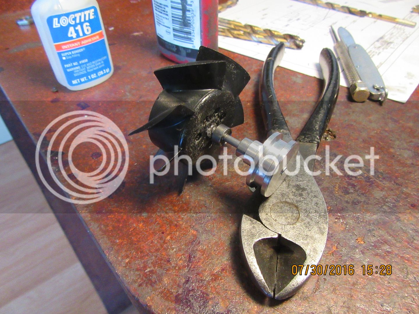
I went up street this morning and invested a whole $11.24 in a small computer fan. After getting it home and tearing everything apart, I have a 7 bladed fan with the correct pitch, 2.25" diameter x about 0.7" thick, and a pair of sealed 3 mm dia. roller bearings. With a little creative design work, it becomes a cooling fan, driven by a 0.100" dia. rubber o-ring. I gave up on the friction drive for the fan, simply because this is so much easier. I'm not going to bother with a fan shroud, as the fan is plastic. (at least until the first time I nick a finger on it.)
 
This is one of those situations where the picture may look better than the part performs. I Loctited an aluminum hub into a cavity in the back side of the plastic fan blade. Either the cavity was off center, or I got the hub in a bit crooked. I have some visible "runout" in my fan blade, relative to the shaft and bushings. I will wait and see how it looks when running on the engine. If it isn't bad, I will leave it. if it looks ridiculous, I may build a fan out of sheet brass.
 
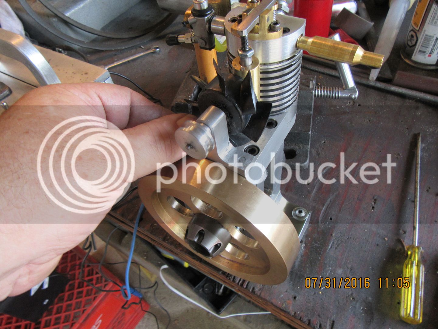
It fits---barely!! There is about 1/16" clearance between the face of the fan blades and the vertical pushrod guide. That's okay--a miss is as good as a mile. The two sealed ball bearings that I scavenged from the fan motor make it roll very smoothly and easily. I think I will have to turn a groove in the outer face of the flywheel to allow the o-ring drive belt to clear the table top. I've spun the fan by hand in the new housing, and the run-out doesn't look as bad as I first thought.
 
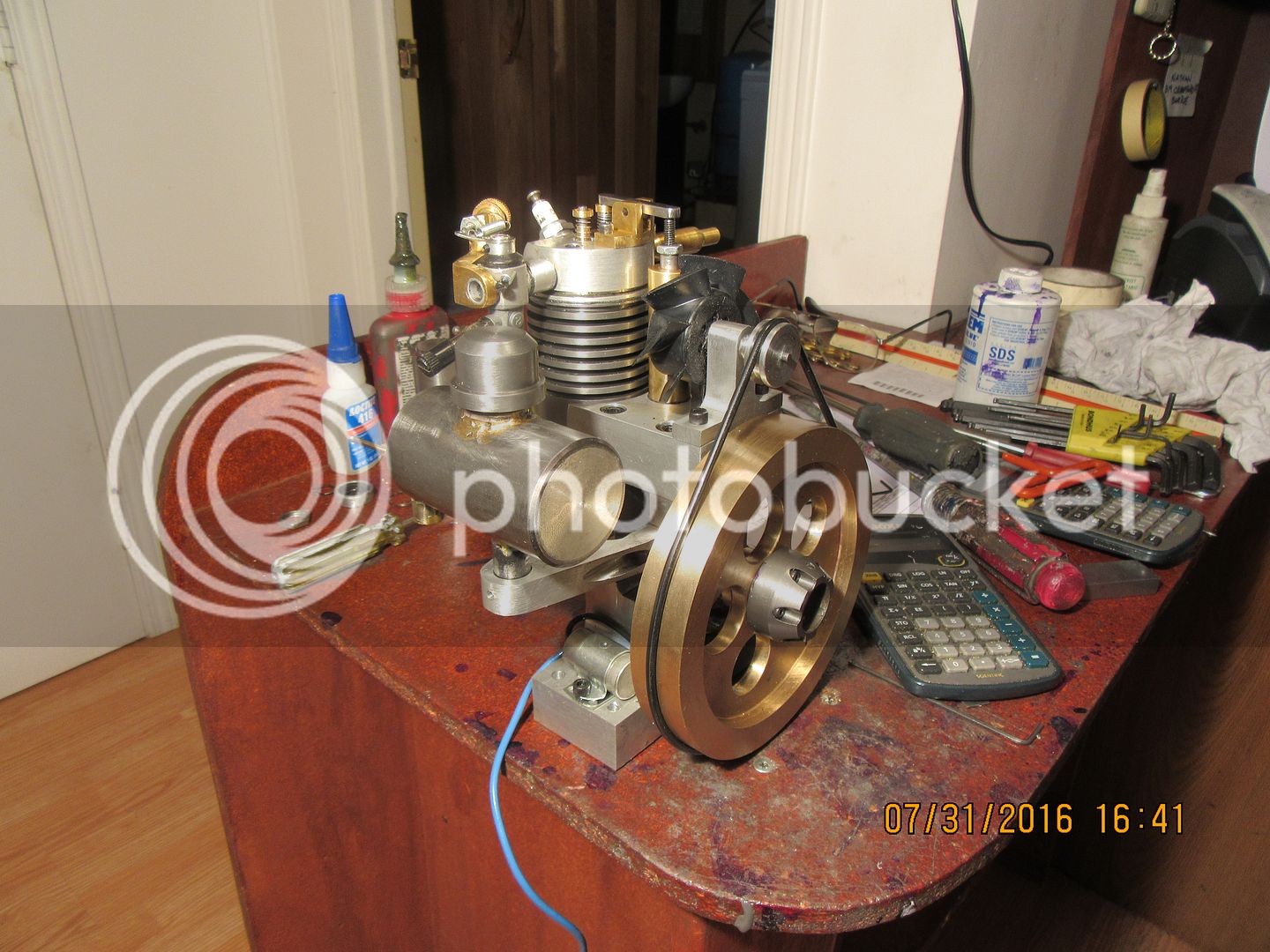
My grandma used to say that something cleared something else "Just by the skin of it's teeth!!". If grandma seen this engine with the new fan and tank support on it, she would say it for sure. Everything fits and clears. I don't want to cut a groove in my nice bronze flywheel to give that o-ring some clearance at the underside, but that doesn't pose a problem for me as I can let the flywheel hang over the edge of my "test bench" when running the engine. The o-ring on there is 1/8" diameter. if I had a 1/16" diameter o-ring (I don't) it would clear without putting a groove in the flywheel. The o-ring on there is stretched too tight, so tomorrow I will try and get a slightly longer 3/32" o-ring to drive the fan. The engine quit on me yesterday, right in the middle of a good long run. I immediately thought, either the ignition cam has slipped or the crankshaft gear which drives the exhaust cam has slipped. When I brought the engine inside today to tap the new holes for the fan support and tank support, I quickly determined that the ignition timing was okay but the valve timing was way off. I will reset the crankshaft gear and try out my new fan tomorrow, perhaps.
 
Today I've been playing in the garage, trying to get everything up and running with the new cooling fan and gas tank. These Traxxas carburetors don't seem to want to lift the fuel up from the tank nearly as good as my home built carburetors do. I had my gas tank mounted in the traditional location, about 3/4" from the center of the carburetor down to the top of the gas tank, but the engine wouldn't stay running unless I constantly choked it. I thought perhaps it would perform better if I cut another half coil off the intake valve spring, and as I installed the shortened spring it got away from me. I recovered the spring itself, but the round brass "keeper" may now be up there somewhere with the space station. I had to make another "keeper". The engine still wouldn't run without constant choking, so I raised the gas tank up higher than I normally would have it, and the engine ran fine. It took considerable "tweaking" to get the engine running with the fan in place, but once I got things adjusted it runs quite well. The fan puts out a considerable breeze, but then it should. With an approximate 5:1 ratio, when the engine is running slowly at 1000 rpm, the fan is rotating at 5000 rpm. I may have to put larger set screws in the flywheel---the ones that are currently in place as per the design keep coming loose. so--that is my update for today.---Brian
[ame]https://www.youtube.com/watch?v=XaNN2ythTwU&feature=youtu.be[/ame]
 
Last edited:
I switched from the Traxxas carburetor to my own home made JAG carburetor because I know my carburetor will lift the gas up from the tank below it. So---the fan works, and the gas tank works in the position I gave on the download of the drawings. The carburetor works. I may still take a half coil off the intake valve spring. The length and strength of that intake valve spring is a very subjective thing. When the engine is brand new, the spring needs to be strong enough to lift the valve up into it's seat, but weak enough to let the valve operate under atmospheric pressure. As the engine "runs in" and the valve gets a bit looser in the guide, you can start cutting half coils off of it. The more half coils you can cut from it, the slower the engine will idle. You just have to be careful and not get too ambitious with your coil cutting. If you cut too much off the spring, then the valve isn't going to seat and the engine will blow back through the carburetor because it isn't sealing properly. I don't remove the head to do this. I just make sure that the piston is at top dead center to prevent "losing" a valve into the combustion chamber. This is very delicate work indeed, and often requires that you have three hands to do it. I have not included drawings of the fan, because the chances of you getting the same computer fan as I did are slim to none. You should be able to see enough from my solid model and my videos that you can make your own copy of it. The fan I used is 2 1/4" diameter.
[ame]https://www.youtube.com/watch?v=0dfxoA7m6qw&feature=youtu.be[/ame]
 
Demo WinZip just expired. Have to pay and then DL Engine Prints. Gus cannot resist building this wonderful engine. But priority comes first. Today as promised will dry test DIY Electronic Ignition Power Pack to fire the 2 spark plugs and move on to start/spin Howell V-2 Engine. Gus is World Best Procrastinator.:cool:
 
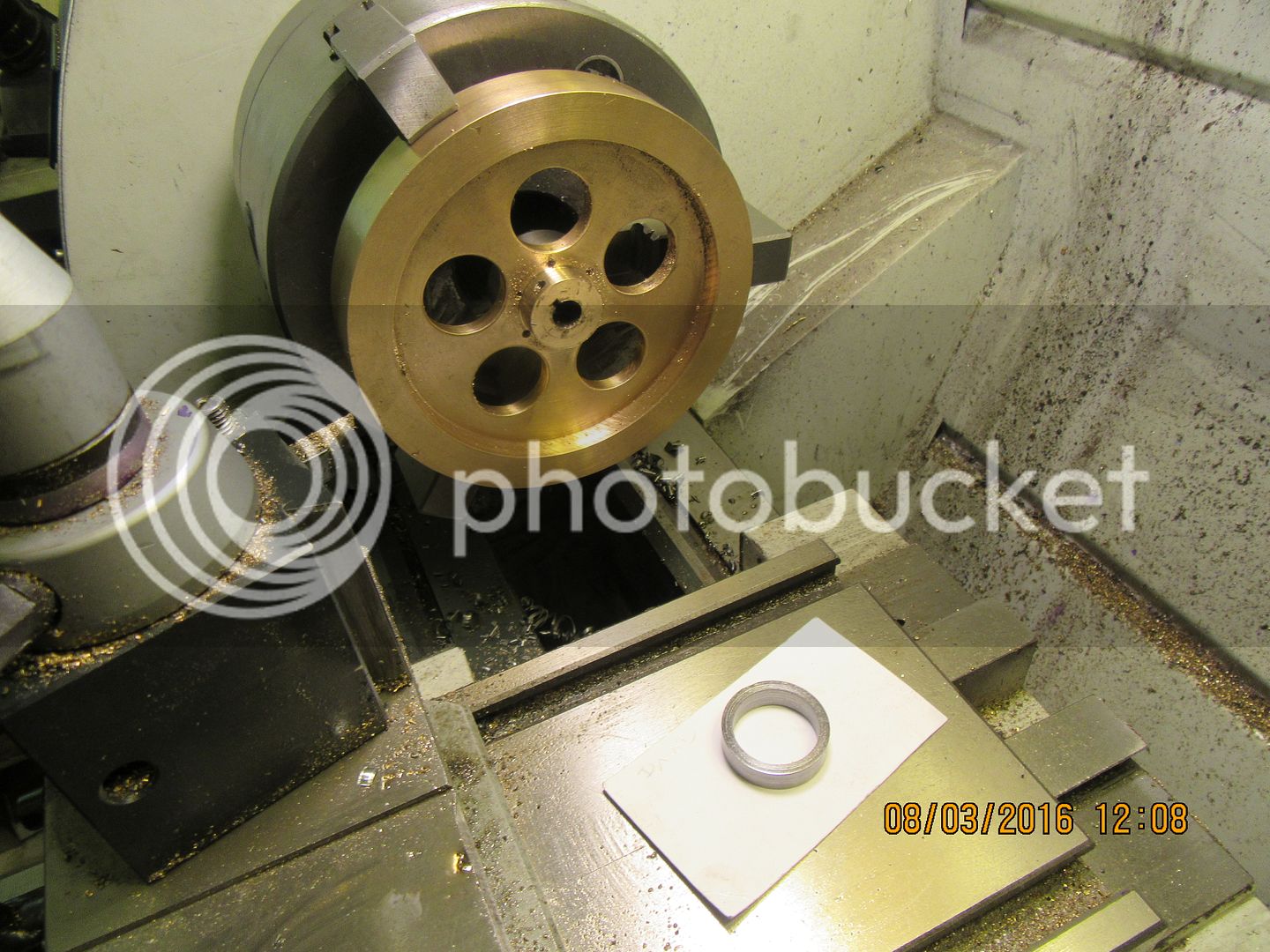
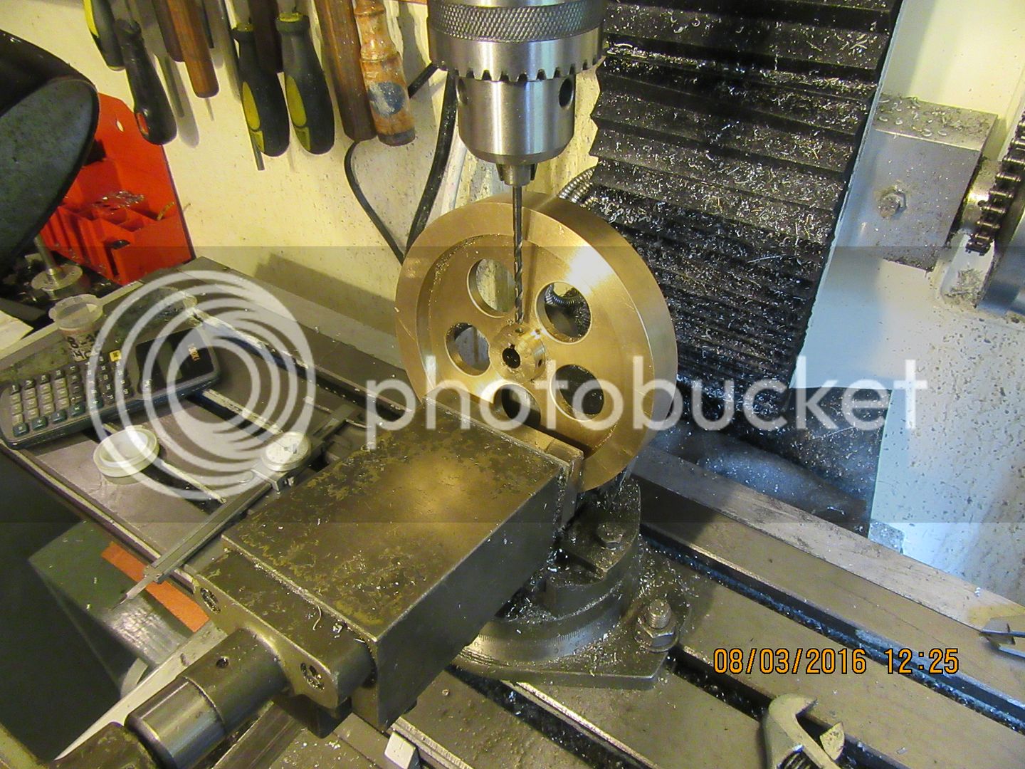
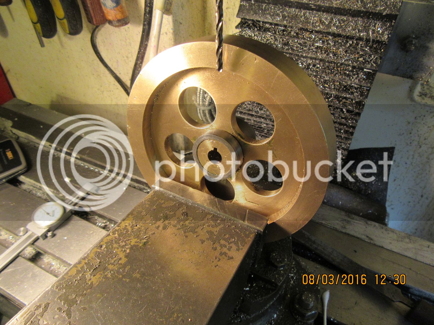
Today you all get to look on while I address a boo-boo. The side of the flywheel which faces the engine has two #8 set screws in it to lock the flywheel in place on the crankshaft. The outer diameter of this hub, as designed, is 0.980" and the bore is 0.375". That leaves an actual wall thickness of 0.302" and reduces even farther to 0.255" over the keyway. Normally, with a #8 set screw which is 0.165" diameter. This should have worked fine, as 0.255" is just a bit more than 1.5 x the diameter of the set screw. However, because of the dynamics of this engine (mainly the weight of the flywheel I think), I can't keep the set screws tight. I tighten them to the point where any tighter would strip out the threads, run the engine for 5 minutes, and CLANK CLANK CLANK---the flywheel is loose again. Now--because there is a lot of work in that flywheel, not to mention the horrendous price of bronze or brass, we fix things. Some measuring and calculating shows that the largest diameter that hub could be is 1.180". any larger than that and the hub interferes with the #10 shcs which holds the ignition points in place. It is very difficult to machine material back onto a hub----so----We make a separate ring of steel which is 1.180" outside diameter x .9375" inside diameter x 0.310" thick. You can see it laying on the white business card on the lathe saddle. We put the reverse jaws in the chuck, grip the outer diameter of the flywheel, and carefully turn the o.d. of that hub down to .9375". Then we move the flywheel over to the mill vice, tilt the mill vice to the angle which the set screws are at, and using the drill bit which was originally used to put the holes in the hub prior to tapping as an alignment guide we position the mill quill exactly over the set screw hole. Now with the X and Y slides locked in place, we raise the head of the mill up out of the way, slather the hub with #638 Loctite, and tap the steel ring firmly into place until it seats against the web of the flywheel. I have ordered an extra long #10-24 tap, which should be here tomorrow. I will then redrill in the exact location that things are now set at for a #10-24 thread. This will let me use a larger diameter set screw and x 3/8" long. I will have to do this twice, as there are 2 set screws at 90 degrees in the hub. the first one will be easy, because I could see the set screw hole to get everything lined up. the scond one will be tricky, because with that steel ring in place, I won't be able to see the second set screw hole to line things up. I may just rotate the flywheel 90 degrees in the other direction so that my second tapped hole is going thru virgins material all the way rather than trying to locate the exact center of a hole I can not see.


Brian,
The key (if it's tight) should keep the flywheel from oscillating. The set screws are only there to keep it from moving axially. If the present set screws didn't hold the larger ones won't either. My suggestion would be to put a larger key and keyway into the flywheel and shaft. When making engines I originally started out by just using 2 set screws at 90 degrees. I was constantly tightening the screws to the point that the crankshaft got all messed up. I bought a set of key broaches and in some cases used Woodruf key cutters and have had no problems since but the fit has to be snug when installed. A flywheel as large as you have (and heavy) should use a good sized key. Another option would be to make your own key and put a very small taper on it (.25 degree). Install the flywheel and line it up with the slot then insert the key and tap it home. This type of key is used on larger engines (hit and miss types) for that very same reason.
gbritnell
 
George--thank you for stopping by and having a look. I thought myself that perhaps the key should have been 1/8" square instead of the .093 square key that I used. Putting a ring on the flywheel and larger set-screws is the "easy way out" of course. If it works, then I'm good. If it doesn't work, then a larger key is my next move. This will involve removing the crankshaft, and I'm trying to avoid that if I can.---Brian
 
The larger set screws have done the trick. I just ran the engine for 25 minutes and the flywheel did not loosen up. The engine did not overheat either, as the fan blows quite a powerful stream of air around the cylinder to carry heat away from the fins. I think I have reached the end of my journey, as far as this engine is concerned. I see that the plans I posted for this engine have been downloaded over 100 times, so I truly hope it will generate some new build threads, and if you want to, by all means you can post your pictures here and continue this thread if you want to. If anyone has questions, or runs into difficulty along the way during their engine “build and run cycle”, by all means ask me, either here or by private email to [email protected]. I am running a mix of 40 parts Naptha gas to one part synthetic two stroke oil as fuel, and an occasional squirt of #30 oil from a squirt can on the gears and other sliding surfaces. ---Brian
[ame]https://www.youtube.com/watch?v=di3_vLtd5LM&feature=youtu.be[/ame]
 
Last edited:
SOS SOS SOS

Hi Brian.

Need your expert advice. Please advice Vertical Engine at TDC ,clearance gap between piston top and outer head. I am getting very bad compression on V-2. With my palm cylinder opening, the compression seems very low compared to your Hit and Miss Engine.
 
Herbie--That looks really good. You are making good progress. What material do you use for the flywheel?---Gus the distance between the top of the piston and the inside surface of the cylinder head is 0.240" at top dead center. My engine has an approximate 5:1 compression ratio, and amazing compression when turned by hand.---Brian
 
Hi Brian. The material i used for the flywheel is cut from an old steel garage door weight that i got for free. Just over 5" diameter and around 3feet long. The outer crust is a real pig to remove but once its removed the remainder machines great.
I got some 2" ali yesterday so this weekend i shall give the cylinder head a go.
 
Back
Top