Vertical I.C. Rupnow Engine

Home Model Engine Machinist Forum

Help Support Home Model Engine Machinist Forum:

This site may earn a commission from merchant affiliate links, including eBay, Amazon, and others.
Hi Guys
Some more progress,
Still working on the cylinder head,


DSC_5076.jpg

DSC_5078.jpg
 
David--That is a beautiful thing!!! Thank you so much for posting the pictures. That just made my day!!!--Brian
 
Herbie--that cylinder head is the one that really takes some thought. There are a number of ways to machine that and paint yourself into a corner, where there is nothing to hold onto for the next operation.---Well done!!!----Brian
 
Today I hunted up my laser tachometer so I could get an rpm reading off the engine. It will set and run at this speed all day, without any stalls or unsteady spots. A blazing 630 rpm, which is quite respectable for these small one lung engines. That big flywheel is doing exactly what I had hoped it would. I also took some video of the atmospheric intake valve so you could see how little they actually move during engine operation.---Brian
[ame]https://www.youtube.com/watch?v=JResK7CQ_-o&feature=youtu.be[/ame]
 
Brian, absolutely beautiful. I am actually going to start on mine now, I hope. Some life issues have gotten in the way and took priority. I'm sorry .
 
Last edited:
Folks--be Aware--The drawing titled "Vertical cylinder-Rupnow engine" is a two sheet drawing. When you print that out you may get both sheets, which is fine, or you may just get one sheet with overall dimensions on it, and wonder what happened to the general arrangement sheet with the bill of materials on it. You may have to manually manipulate that particular pdf to show and print the second sheet.---And--If you have any questions about the ignition cam, the flat is tangent to the 0.625" diameter.---Brian
 

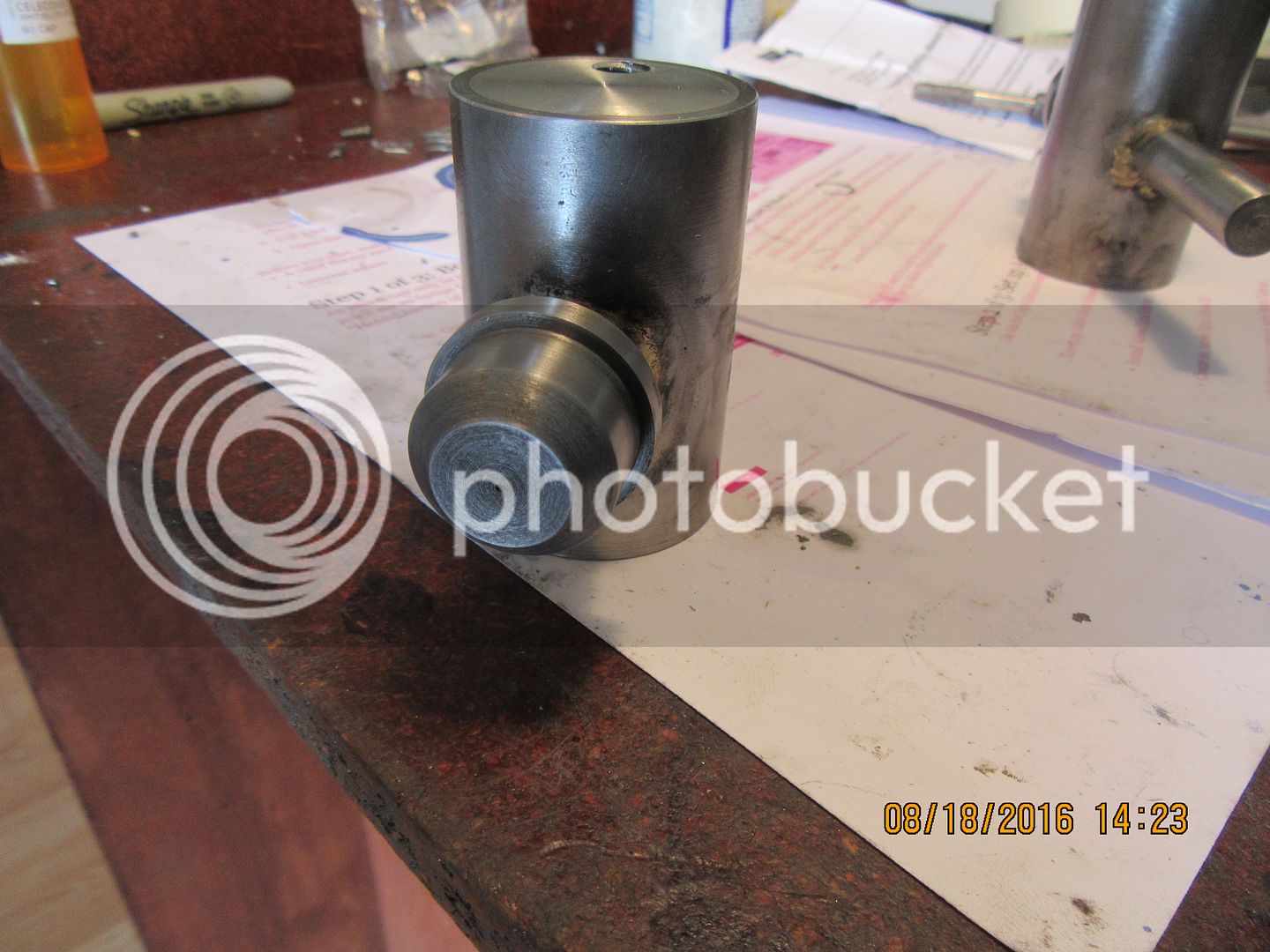
A bit more progress over the weekend. A couple of valves with handles.
 
Looking good Herbie. I see that you have skipped a step on the valves, namely the short section which I would have turned above the tapered face to ensure concentricity between the stem of the valve and the head of the valve. If you machined them in a 3 jaw chuck, which will have .001 to .003" runnout then you will not have concentricity between the stem of the valve and the outside diameter of the head. I very recently posted a thread about "Making valves for model I.C. engines" on this forum. You should have a look at it. Your valves may work as built. Once you have removed them from the 3 jaw you will never get them back in the same way, so it's too late now to put them back in and turn that additional step.---Brian
 
Oops. Yes i did follow your thread on building valves Brian but being my birthday weekend i must have forgotten that part. (Dissolved a few too many brain cells). The good news is that i bought two yards of 3/8" rod to allow for mishaps Rof}
 
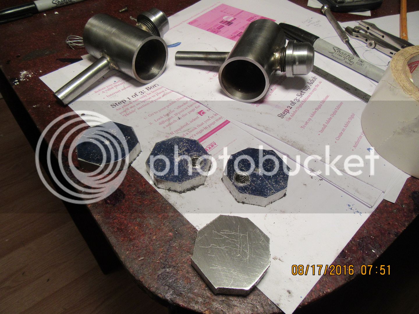
Today we are making gas tanks. Not for this current engine, but for other engines I have been "robbing" parts off of. The actual "tanks" are pieces of 1 3/4" o.d. steel pipe, with a 3/8" deep counterbore in each end about 0.030" larger in diameter than the stock i.d. of the pipe. The filler necks are short sections (0.9" long) of 1/2" nominal schedule 40 pipe (0.830" o.d.) with pipe threads on both ends. (I buy 2 1/2" long pipe "nipples" at the hardware store). I leave 1/2" of full threads on the end and turn down the remaining 0.40 inches to 0.218" diameter. This turned diameter fits into a drilled 27/32" hole in the side of the tank, and is silver soldered in place. I plunge mill a shallow "flat" on the side of the tank opposite the filler neck and silver solder a piece of 1/2" diameter cold rolled steel there to act as a tank mount. The "gas caps" are turned from 1/2" threaded cast iron pipe caps.
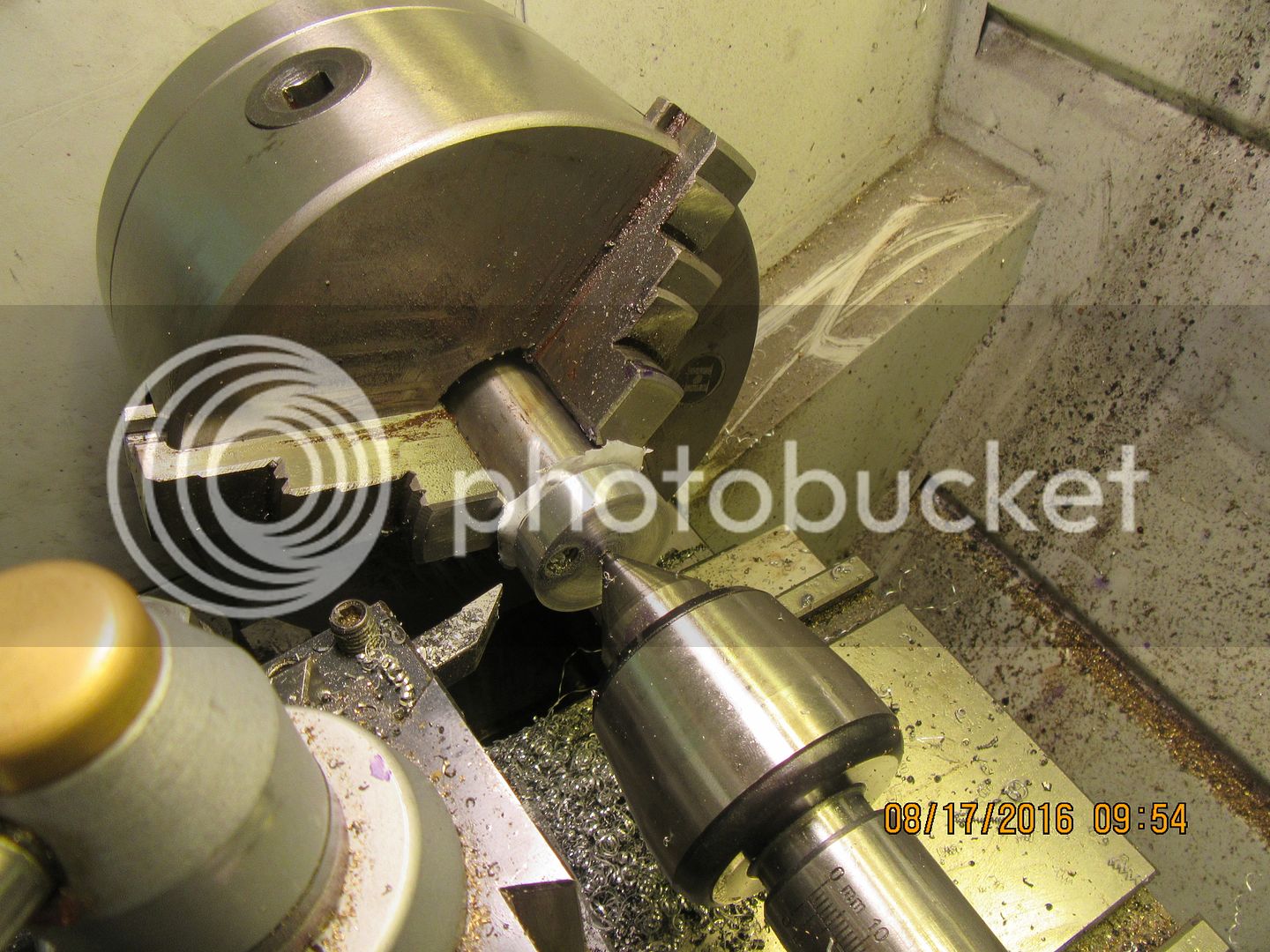
The aluminum end plates are first layed out on a flat piece of 3/8" plate, then center punched with a good deep punch mark, then rough sawn to shape on the bandsaw. Two of the end plates have 3/8"-16 holes drilled and tapped through them, 1/2" off the center. (they will become the "outlet" from the tanks.) The next step will be to put 2 sided carpet tape on the "non punchmark " side of the end plates, then mount them one at a time against the nose of the 3 jaw chuck with the punch mark facing outwards. My live center in the tailstock will be centered in the punchmark and locked, with considerable pressure against the plate to hold it in place. Then I take small cuts and bring the outer diameter down to about 0.005" less than the counterbore in the ends of the tank. I put a bit of plasticene into the 3/8" threads to protect them, and then J.B. weld the endplates into the tank counterbores. The centerpunch mark faces in towards the center of the tank so it is hidden in final assembly.
 
Last edited:
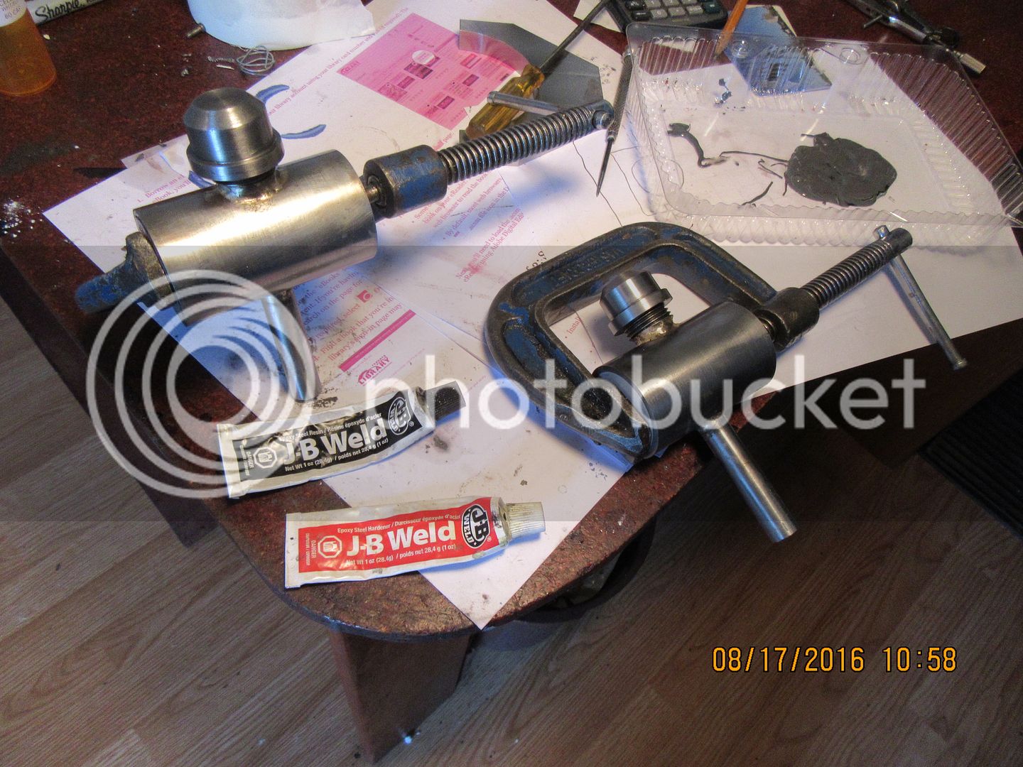
I found that on this lathe, the 3 chuck jaws are larger in diameter at the center than the gas tank ends I wanted to turn.So--I chucked up a piece of 1 1/4" round bar, faced it, and let about 1/2" protrude from the jaws. That way, I could butt the sticky taped side of the cut out plates up against the end, and since they are just a shade under 1.5" finished diameter I was able to take consecutive cuts across the full width of the plate until I had it down to the correct diameter. I repeated this operation for each plate, then mixed up a batch of J.B. Weld, coated the edges of the 3/8 plates and pushed them into the counterbores in the pipe ends. a pair of C clamps ensure that the plates are fully seated in the counterbores, and after 24 hours I will do a bit of clean-up and put these tanks back onto the engines that the tanks were "borrowed" from.

 
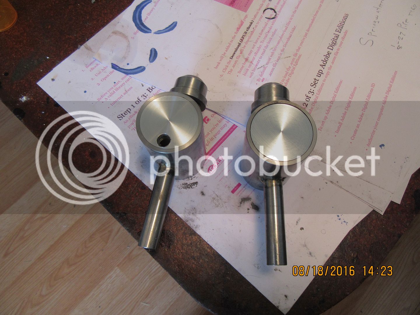
And the last of this little "build within a build" series. The gas tank ends never end up perfectly "square" in the counterbore of the main tank body.--So---After the J.B. weld has set up for 24 hours, I stick the tank body back in the 3 jaw chuck on the lathe, and take a "facing cut" across the ends of the tank. This squares everything up nicely and makes it pretty. Another feature which you can barely see, but is extremely important, is a 0.040" diameter breather hole drilled thru the center of the gas cap. That little hole has an enormous effect on how well your engine will run. The tank cap and the filler neck that it screws onto are both tapered pipe threads. Being made from iron, the cap is heavy enough that just the vibration from a running engine will make it screw itself onto the filler neck tightly enough that the tank becomes "vacuum locked" and fuel won't flow freely to the engine carburetor. This is guaranteed to make you crazy trying to figure out why your nice running engine stalls and quits intermittently for apparently no reason. I have been caught by that one enough times over the years, that I always drill my filler caps when I make them.

 
Todays effort is making the con rod. I have ordered a block of aluminum 6"x5" x2". From that I should get a cylinder mounting plate and a frame. Also ordered 4" of 55mm cast iron for the piston.

image.jpg


And a couple more fiddly bits done over the weekend. I find this hobby 90% setting up and measuring, leaving about 10% for actual machining. All good fun. :D
My cast iron and block of aluminum should arrive today so heaps to keep me busy this week
 
Last week I realized that I had made no provision for a pulley on this engine, and that as a consequence, it couldn't work for a living. Now, that's just not right!!! All of my engines have to do a bit of work. I won't have any free-loaders setting around on my shelves. I don't have a lot of things for my engines to drive. Let me see, I've got the generating station, made from an old bicycle dynamo, I have the slinky machine, but it's getting pretty old and tired. I have the single acting lever pump, the sawmill, the buzz-saw, and the log splitter.--I like to suit the "work" to the size of the engine, and since this is quite a powerful engine, I decided to let it earn it's keep lifting 5/8" steel balls on my "Jacobs Ladder", driving thru my cone clutch. The distance between the three different "stations" is dictated by the lengths of rubber O-rings that I have available. They make excellent "drive belts". I had to move the engine inboard, away from the edge of the table to get all the pulleys to line up, so I put a couple of 1/8" parallels under the engine to give a bit of clearance for the o-ring that goes around the flywheel. Now that I know that the engine can "earn it's keep" doing some honest work, it will soon be dismounted, cleaned up, and retire to live out the rest of it's days on one of the shelves in my office. (Which are all getting terribly crowded from six years of engine building). I'm looking for updates from builders out there. I know where Herbie in Australia and David Lloyd in New Zealand and Mark from Virginia are on there builds, but I have lost track of everybody else. Please post an update to show the current state of your builds.--I'm curious.----Brian
[ame]https://www.youtube.com/watch?v=xK1RvOyPaug&feature=youtu.be[/ame]
 
Great video Brian. I love the idea of " no freeloaders ":D
 
Back
Top