Time for a new Horizontal Hit and Miss engine

Home Model Engine Machinist Forum

Help Support Home Model Engine Machinist Forum:

This site may earn a commission from merchant affiliate links, including eBay, Amazon, and others.
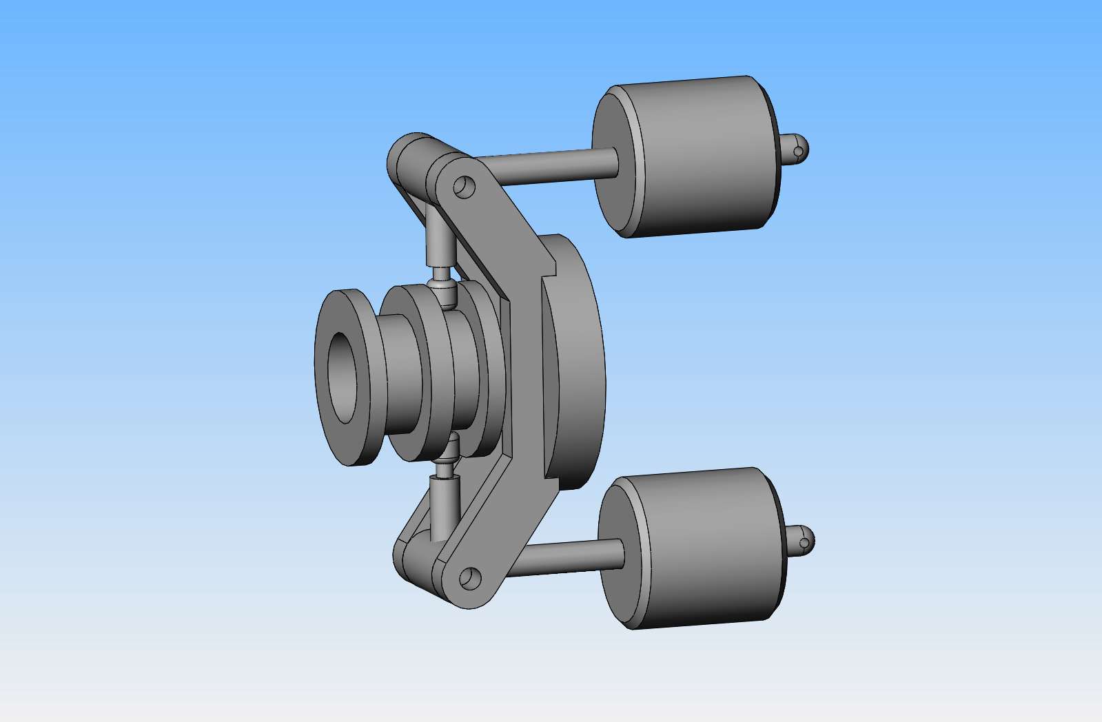
This video shows a set up whereby I can set the rpm of the governors to what it would be on the actual hit and miss engine, and see if the lockout pin in the center of my 60 tooth gear operates. This test was a definite fail----at 250 rpm, the governor weights and lockout pin didn't move at all. My conclusion is that I need a lighter governor return spring. The spring that I have in there now is one that I just picked up out of my tray full of springs and installed because it fit. Next step will be to replace it with a much lighter spring and try this test again.--Edit--Should have said 'When centrifugal force activates my governor"--Brian
 
Last edited:
This video shows a set up whereby I can set the rpm of the governors to what it would be on the actual hit and miss engine, and see if the lockout pin in the center of my 60 tooth gear operates. This test was a definite fail----at 250 rpm, the governor weights and lockout pin didn't move at all. My conclusion is that I need a lighter governor return spring. The spring that I have in there now is one that I just picked up out of my tray full of springs and installed because it fit. Next step will be to replace it with a much lighter spring and try this test again.----Brian


One of the reasons I find this design process interesting is it's so far out of "my world." All I know about springs is some Physics 101 or Statics stuff on spring constants. And I've wound a few to different designs, stuff like "wind .010" music wire 1" long, close wound." These things don't really tie together easily.

Did you test how fast it has to spin before the spring pushes enough? Is it engaging marginally too high, like 300 RPM, or closer to 500? It might help you know how much weaker the spring needs to be.
 
CFLBob--95% of what I am doing is "Try it and see what happens" stuff. I know a fair bit from experience and from watching ten thousand videos, but it is mostly "Seat of the pants" engineering. My test today shows that the spring I am using is way to stiff---I needed to jack the rpm up to 800 before the governor would engage. So next thing was to try a few weaker springs from my spring collection. I came to the conclusion that not everything is "scaleable". Now I know why the full size Hercules engines ran the governor off a smaller diameter gear and it revolved much faster than my governor which is ran off the cam gear, which only rotates at 1/2 the crankshaft speed. It is much easier to get consistent, repeatable results from a faster turning governor and a much stronger spring than from a low speed governor and a weaker spring. Eventually I used the lightest spring I had and started reassembling things on my engine. I have two compression springs to deal with here---one inside the governor which I tested today and is difficult to access, and one which fits inside the lockout lever and is easy to access. Ergo, my best hit and miss action will be tuned by monkeying with the spring in the lockout lever. I don't think I have ever seen a model engine using this style of governor, and perhaps today I found out why. I'm not terribly concerned-if I absolutely have to, I will change the governor to the Farm Boy sliding sleeve on the crankshaft style. This is the style that all my other hit and miss engines use. If I do change the style of governor, 90% of the engine remains unchanged. I've only sold one set of plans, and if I change the governor style I will send the guy new updated prints of anything that changes.---Brian
 
Hi Brian, I heard depleted uranium is a bit more dense than lead... but mentioning that on an open website possible means I'll have a visit from the CIA now... I just don't know where to get that stuff. Tungsten is a reasonable alternative.

But maybe to get from 800rpm to 250rpm you simply need to add a lot more coils, or decrease the pre-load on the spring you have to make it 31% of the load as applied now.
K2
 
I puttered with an under performing governor years ago. The first idea was to increase the weight of the fly balls by adding lead. No effect. I then read a little booklet on governors by Tee publishing (?) and the jist was the weight of the fly balls make no difference in a governor, IIRC, is this true? Seems counter intuitive. I think a more effective fix for governor performance might be to lengthen the arms.
 
The whole idea of a governor is a balance between mass of Bob weights, lever arm, spring pre-load and speed of rotation. From those 4 factors, altering any one will have an effect. But the degree to which any one affects the "set-speed" is really determined by the design. A bit of relatively simple maths can make a numerical model of a design, then that can be tweaked to a "working" condition without cutting metal.
Brian, if you want to send me a drawing of the governor I can do a mathematical model and suggest the optimum change(s).
But I know you have a "natural feel" for these mechanical things, and are happy to manually tweak each variable as suits your design and boxes of bits (springs in this case?).
K2
 
I just finished reassembling everything. Very little was changed. I did end up putting a very light spring inside the governor spindle, and I added a "wear ring" between the 60 tooth gear and the side frame of the engine. I will do more engine testing later today and give an opinion.
 
An honest opinion--Adding a spring inside the governor didn't do much for me. In fact, if anything, the engine is less inclined to hit and miss now than it was before I added the spring to the governor. The problem seems to be that the camshaft simply isn't turning fast enough to operate the governors properly. Okay, I've learned something. I'm disappointed, but this is the way we learn. I've only sold one set of plans, but I will refund the guys money and give him the option of a refund or waiting for a new set of plans. My next amazing stunt will be to see what's involved in putting a different governor and a sliding sleeve on the crankshaft, similar to that used on the Farm boy.
 
Hi Brian, did you try without a spring, just to see at what speed the bob-weights actually fly out? If this is below the speed you want when the engine is idling in hit and miss mode, then there is hope for the design. The spring can only raise the speed of operation from the "no-spring" condition. - I think?
Of course, the "traditionalists" would note that for simplicity, the governors were usually geared-up from crank speed, on "slow" engines. But mathematically, all things are possible, but some things are unreasonable.
Never stopped you from trying though!
Keep up this interesting project.
Regards,
K2
 
Hi Brian I would have tried heavier weights on the governor which would cause them to activate at a lower speed. Worth a try before a re design. Drill a hole in them and fill with lead John
 
An honest opinion--Adding a spring inside the governor didn't do much for me. In fact, if anything, the engine is less inclined to hit and miss now than it was before I added the spring to the governor. The problem seems to be that the camshaft simply isn't turning fast enough to operate the governors properly. Okay, I've learned something. I'm disappointed, but this is the way we learn. I've only sold one set of plans, but I will refund the guys money and give him the option of a refund or waiting for a new set of plans. My next amazing stunt will be to see what's involved in putting a different governor and a sliding sleeve on the crankshaft, similar to that used on the Farm boy.
Brian,
Admiring your tenacity, and sharing your frustration.
Would you consider modifying the weights so the mass center of gravity is moved farther out the moment arm?
Perhaps the red area could be ground, filed, milled away as a last ditch effort before scrapping?
governor edit.png
 
IF the above diagram is correct for Brian's design then I have to agree with Raveney.
It appears to me most of the mass is inboard (and even a bit below) the pivot point. In my mind there would be little to no centrifugal force acting on the mass to fly out in a direction along the plane of the page.
In fact, if there is any force it will be against the pivot pin NOT in a direction vertical on the drawing which would be necessary for the weight to move. And possibly even some in a downward direction.
I agree that the predominance of the mass should be out where Raveney has drawn the big black dot. Leaving only a thin section to act on the pin. Almost like you should flip the weights over on the pins.

Brian I think you can solve this problem with a little bit of rework on the weights. I wouldn't abandon it yet.
 
Last edited:
There isn't enough room to add anything to the existing governor weights. They can't be taller or they hit the connecting rod. They can't be longer on the opposite end because they hit the engine sideplate. They could be drilled and filled with lead, but there is such an insignificant difference in the weight of lead and the weight of steel that I doubt that would help. Today I'm off on a quest to use a different style of governor and try and save all the existing parts of the engine that are already made. Thank you for your interest and your comments. This rodeo isn't over yet.---Brian
 
There isn't enough room to add anything to the existing governor weights. They can't be taller or they hit the connecting rod. They can't be longer on the opposite end because they hit the engine sideplate. They could be drilled and filled with lead, but there is such an insignificant difference in the weight of lead and the weight of steel that I doubt that would help. Today I'm off on a quest to use a different style of governor and try and save all the existing parts of the engine that are already made. Thank you for your interest and your comments. This rodeo isn't over yet.---Brian
The excellent suggestions given suggest removing material inboard of the pivot pin, not necessarily adding, making taller etc. It could be a simple fix that would only take a few minutes to machine away some material and try.
 
So, this is the Farm Boy style governor. It will fit on one end of the crankshaft, and the butterfly shaped part will bolt to the side of the flywheel, the sliding sleeve slides back and forth on the crankshaft, The lockout arm end (which is not shown) will fit in the unoccupied ring and pivot over the camshaft centerline. note that I do not have drawings of the Farm Boy engine here, but there are enough videos of other peoples builds on the internet that 98% of the information is there, if you hunt for it.
yQH9Ws.jpg
 
Hi Brian,
Just found 10 mins to review your design per post #241, and agree with the idea from post # 272 etc by Raveney and Dsage, but you know what is possible in the available space. But doubling the "acting" mass only reduces the effect of the governor from 800rpm to 800/(sq.root. 2) =571rpm. (v= sq.root of (F x r / m) ). Doubling the speed of the governor (if fitted on the crankshaft) gives you the 800 rpm operating speed at 800 rpm of the crankshaft, not 800 rpm of the camshaft, so you need more leverage, and or mass using this (equivalent) design on the crankshaft instead of the camshaft to resolve the issue. Just a bit more work than simple tweaking.
Regards,
Ken
 
Last edited:
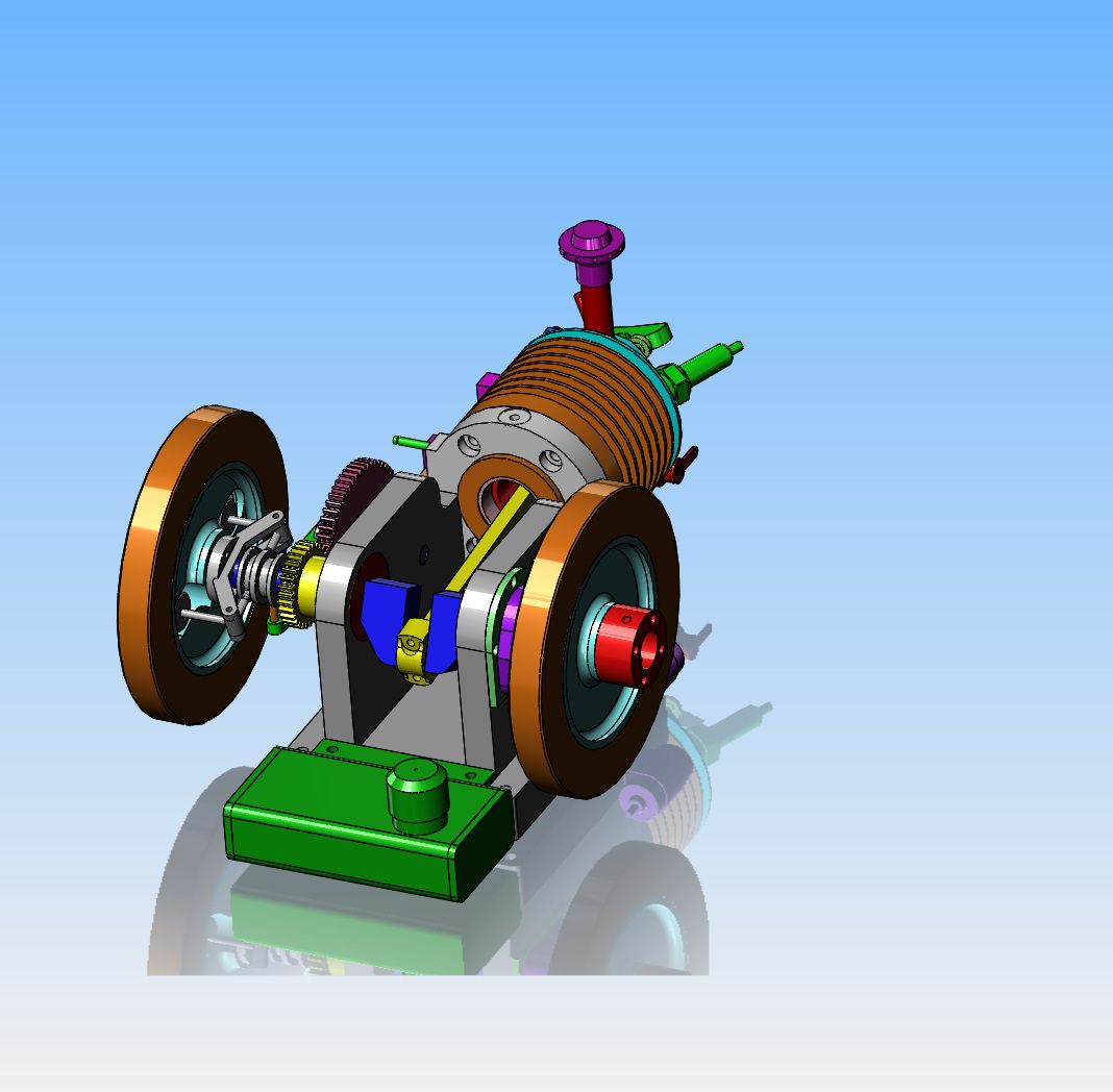
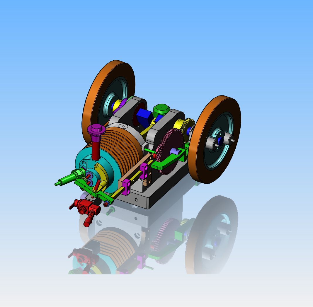
Thank you Steamchick--I have spent today redesigning the engine for a Farm Boy style governor. Surprisingly, very little of the existing engine has changed. The crankshaft gets swapped end for end, the engine sideplate on the governor side gets replaced (or repaired) , and the 60 tooth gear gets recut. One flywheel gets some clearance holes added for the governor weights, and the starter hub gets moved to the flywheel on the other side of the engine. One of the pushrod guides gets moved over a bit, and the lockout lever gets replaced. Since I have the capability to weld aluminum, I may plug the hole in the side of the engine sideplate which originally held a 7/8" roller bearing and simply add a threaded hole to the plug to accept a shoulder bolt. The new shoulder bolt will be custom machined with a slot to hold the new lockout arm.
7mTVhP.jpg

LIE9cP.jpg
 
Although it is moot, as Brian has done a complete redesign, I cannot see any significant advantage in removing the hatched red bit from the narrow actuating fingers as proposed by Raveney and supported by several others.

The radius of gyration of the weight is one consideration, but what also matters is the the moment of the mass about the pivot pin, in the plane of the paper. Now, in the extended position, the mass of said red area is more or less equally disposed, half above (outboard of) and half below (inboard of) the pin. Net result - nada.
 
Last edited:

Latest posts

Back
Top