You are using an out of date browser. It may not display this or other websites correctly.
You should upgrade or use an alternative browser.
You should upgrade or use an alternative browser.
Super Tigre G32 1cc diesel - a 5cc version
- Thread starter Ramon
- Start date

Help Support Home Model Engine Machinist Forum:
This site may earn a commission from merchant affiliate
links, including eBay, Amazon, and others.
- Joined
- Jan 30, 2011
- Messages
- 365
- Reaction score
- 72
Hi Brock - just escaped from garden duties ;D
There shouldn't be any reason why this engine could not have a glow conversion - as long as the compression ratio is around 10/12 to 1 it should work okay. That would probably entail lowering the liner slightly and altering the head to suit so that the plug is not buried too deep. I would think it would be very noisy with an open exhaust however but must admit it's a lot easier to obtain glow fuel than diesel so that fact alone may make the proposition more attractive. I have no plans to do so as such though nearer the time I could draw a head to see how it looks.
For me this is very much an attempt to replicate the original at 5cc as best I can but others may see it as a basis for taking further. Doing away with the fixed back end for a start would certainly simplify matters
Ho hum back to the soil!
Regards - Ramon
ShedBoy
Senior Member
- Joined
- May 13, 2011
- Messages
- 792
- Reaction score
- 34
The fuel issue is why I asked. The last time I messed with a diesel was 20yrs ago and getting ether was an issue back then. As for the sound I reckon it would be like music to the earplugs, neighbours would disagree though.
Brock
Brock
- Joined
- Jan 30, 2011
- Messages
- 365
- Reaction score
- 72
Hi Guy's - Well, you win some and you lose some : - Before we get to a glow head Brock, first I need a crankcase !!
Having burnt myself out in the garden yesterday - one day of sunshine in days of seemingly endless rain - I thought it far more sensible to get into the workshop and on to the next stage - after all you shouldn't overdo these things now should you .
.
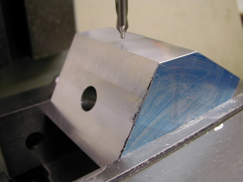
After making up a spigot for locating the bore on later milling ops the blocks were set up and 4mm pilot holes drilled and reamed at the intake location. These will be used for setting purposes later before being opened up to final size. The position of the intake hole relative to the valve sleeve bore and the inner face of the cavity was marked out as a double check on position but the actual positioning was all done from coordinates
Itching to get on,the first block was set up on the lathe for boring out the top face through to the cavity for the liner
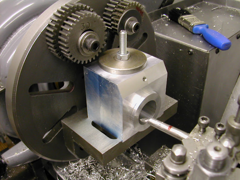
Although I was aware I had dimensioned the depth of the transfer ports and drawn the bore straight through it soon became clear I hadn't thought this through fully - (oops!) Not giving this too much thought then I'm afraid I blindly ignored the interupted cutting feedback - it was difficult to see till the bore had increased - thinking it was the breaking through into the sides of the cavity oh:
oh:  oh:. The penny dropped too late of course before it was realised that I was eating into the back face of the cavity. Well after the usual 'Deary me, look whats happened' kind of phrase
  (yeh you wanna believe it
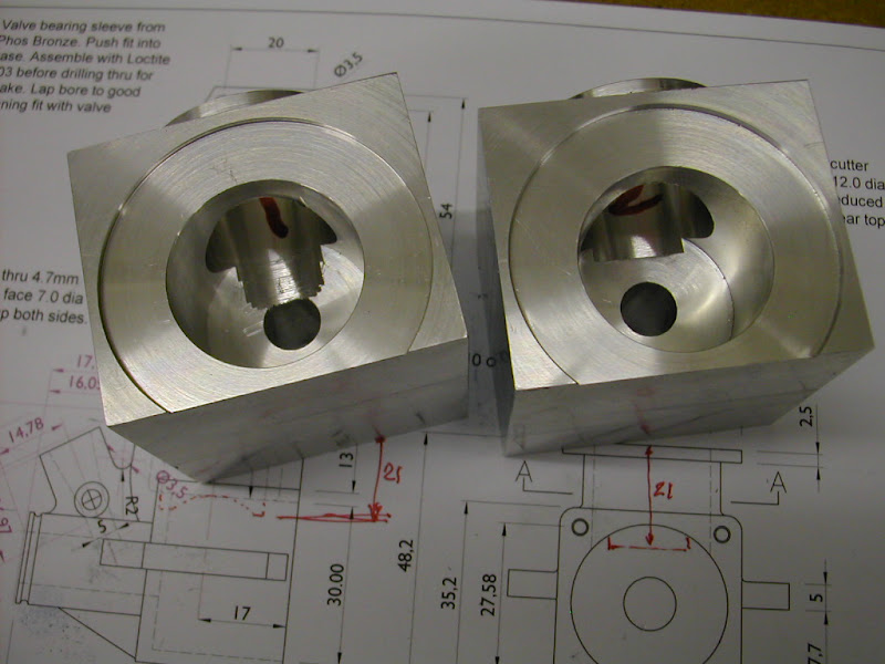
  ) I could see the error of my ways and decided to break it down to see what it looked like before going any further. Taking a good look at what had transpired it looks as if it can be saved by setting it up and boring out for an insert. This is now very definitely 'Case # 1' to be used for all set ups. Set the second case up and bored to a very definite 21.0mm deep which was a big improvement.
So an inauspicious day ended with these ...
Not much to show so far but hopefully tomorrow will see #1 case recovered and a start on shaping the outsides - unless of course the 'Sun do shine' - but then it usually does in the shed
Regards for now - Ramon
Having burnt myself out in the garden yesterday - one day of sunshine in days of seemingly endless rain - I thought it far more sensible to get into the workshop and on to the next stage - after all you shouldn't overdo these things now should you
After making up a spigot for locating the bore on later milling ops the blocks were set up and 4mm pilot holes drilled and reamed at the intake location. These will be used for setting purposes later before being opened up to final size. The position of the intake hole relative to the valve sleeve bore and the inner face of the cavity was marked out as a double check on position but the actual positioning was all done from coordinates

Itching to get on,the first block was set up on the lathe for boring out the top face through to the cavity for the liner

Although I was aware I had dimensioned the depth of the transfer ports and drawn the bore straight through it soon became clear I hadn't thought this through fully - (oops!) Not giving this too much thought then I'm afraid I blindly ignored the interupted cutting feedback - it was difficult to see till the bore had increased - thinking it was the breaking through into the sides of the cavity
So an inauspicious day ended with these ...

Not much to show so far but hopefully tomorrow will see #1 case recovered and a start on shaping the outsides - unless of course the 'Sun do shine' - but then it usually does in the shed
Regards for now - Ramon
- Joined
- Jan 30, 2011
- Messages
- 365
- Reaction score
- 72
Hi again, just an update on the current state of play. Managed to reclaim the mis-bored case successfully yesterday but laying a path to the new extension took precedence for the rest of the day given a dry spell in this very wet period.
Had a good days milling today however but still not got to the crux of the matter in dealing with that rear end but that's not far away now. The camera I have been using for all of these shots - the little Nikon Coolpix 2000 - appears to be begining to fade , some of the images taken yesterday turning out quite dark and it's very slow between shots. Shame really it's been a great little camera for this purpose. Fortunately theres a far less used Fuji languishing in the drawer that can now be pressed into service.
Despite that here's a few pics of the latest progress............
Reclaiming the case began with making an insert like a thick washer about .5mm thicker than required. The hole (in the insert) was bored to 9.95 and the outer rim cut at a half degree angle so that as it would be pressed into it's recess (and Loctited) hopefully the join would be near invisible. Once this was done yet another expanding mandrel was turned up - I just love making these things, they work so well
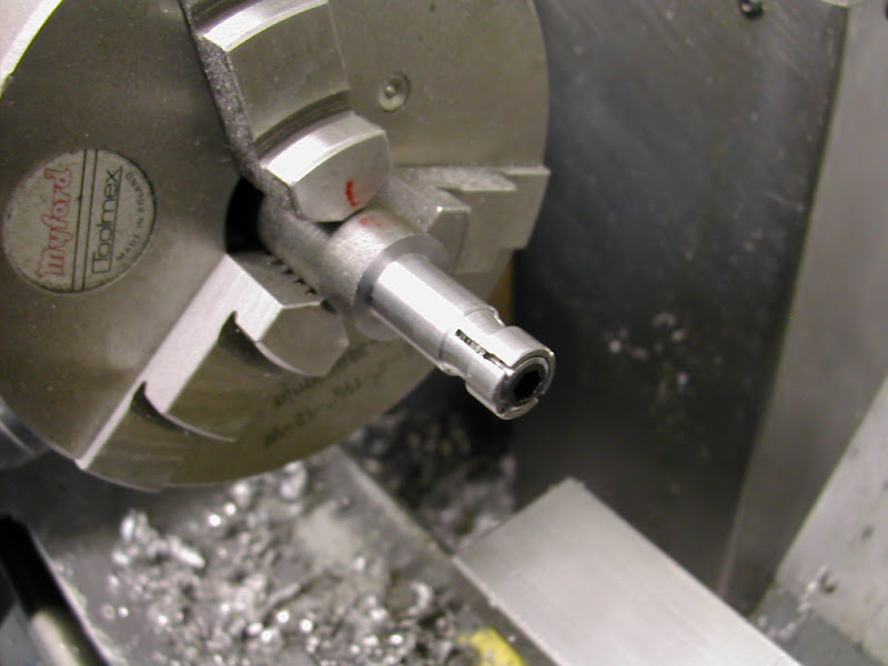
This held the case with less than .01TIR and the recess was then bored until the back face just cleaned up and the insert would just enter. As with pinning the recess edge was not deburred. Held on a previously turned spigot the insert was pressed in using the tailstock.
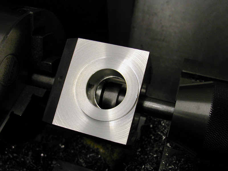
Once the Loctite had cured this was faced back to the original depth then the case set up as before for boring out for the liner. Finally by using the chucking reamer by hand from the outer end that .05 left in the bore of the insert was reamed inline with the original bore. The reclaimed #1 is on the left
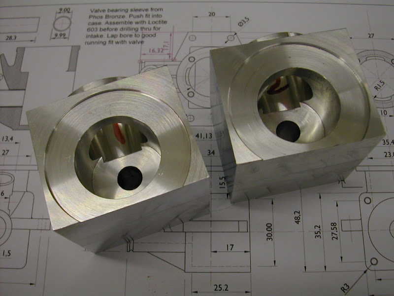
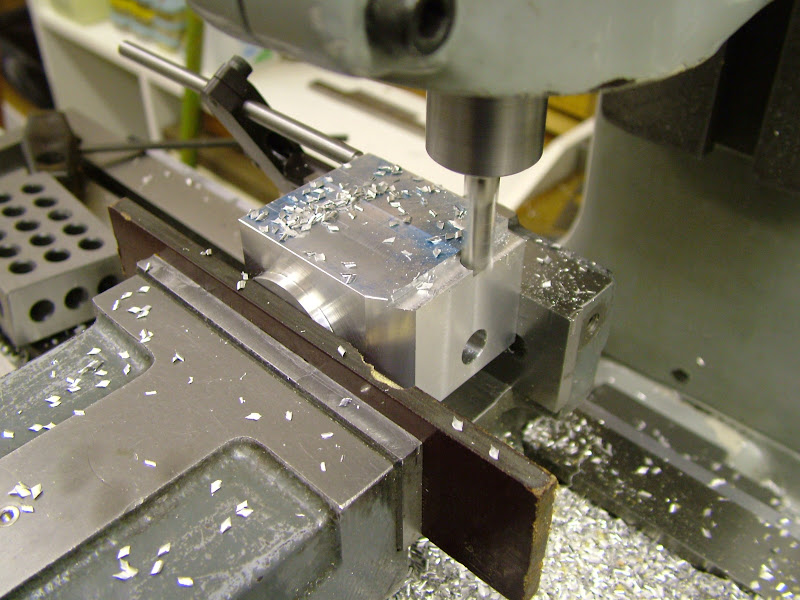
Back to square one rough milling the outer faces could begin and this was done in the vise with packing to protect that finish turned top face. First the rear end was reduced each side to a 'reasonable' finish as this was to be used for subsequent setting up then the sides above and below the lugs were taken out to within 1mm of finished size
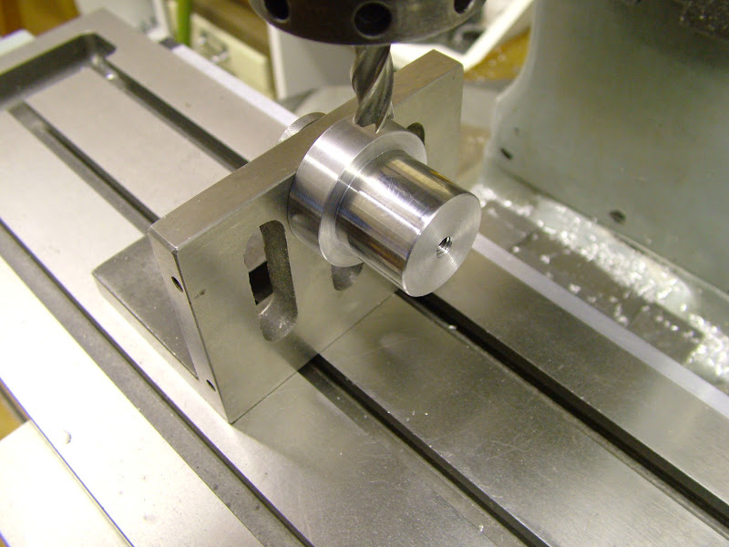
Now the finishing could begin so first off was to mount that spigot previously machined on an angle plate and square it up on the mill. The mill spindle was centred accurately about the centre line of the spigot
The case was set square to the table via that reduced width then the lower (actual - the top in the shot) face was then milled as a datum and the lower faces of the lugs and crankcase width finished off to size
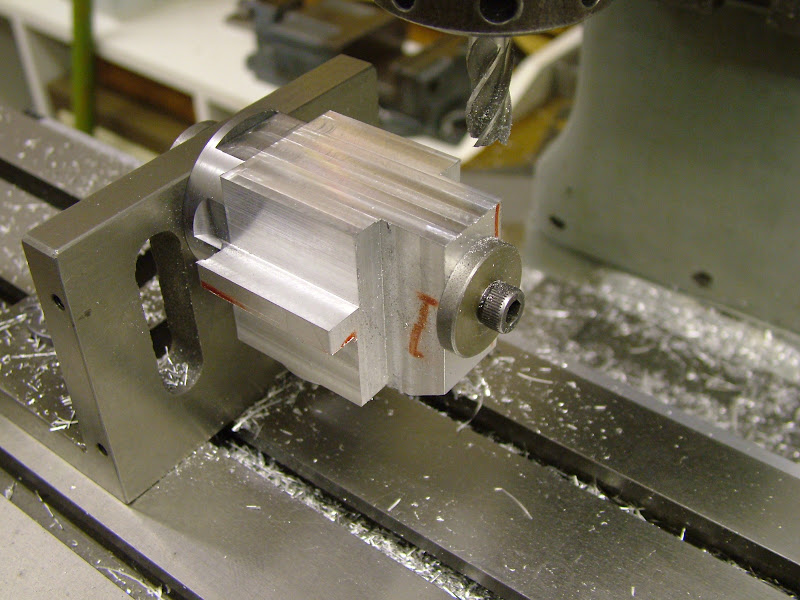
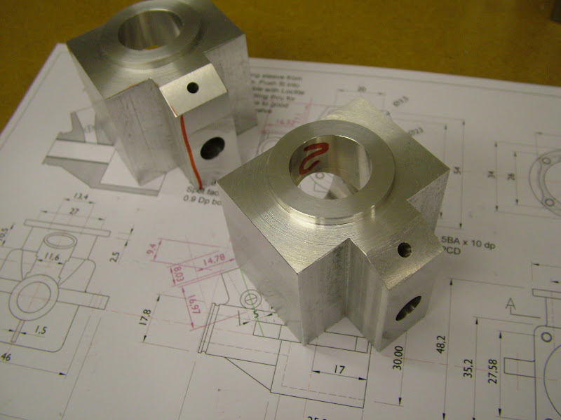
The case was rotated for the sides above the lugs and the lugs themselves to be finished this time using an end mill which had had the corners radiused. The top edges of the main body sides were then milled before setting up again to radius the edges with a corner rounding cutter ......
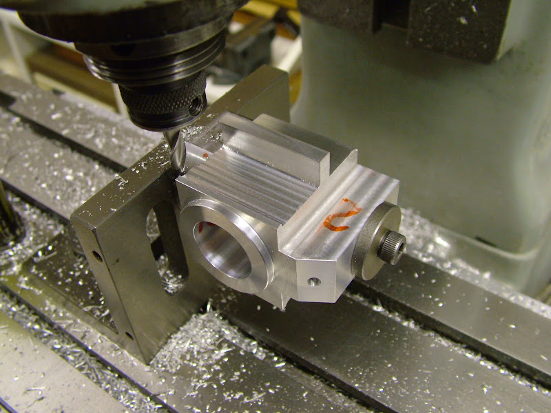
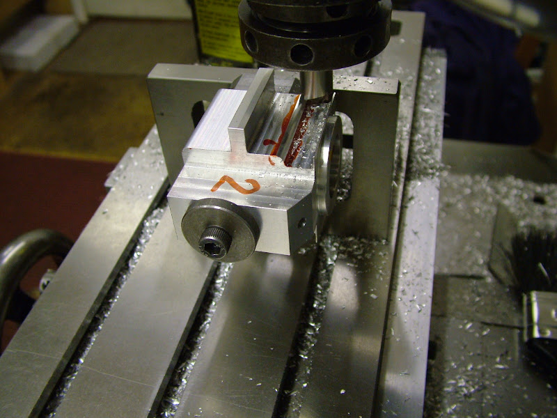
.....and this is how they look tonight..
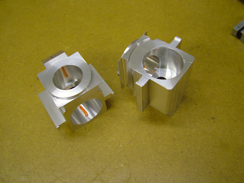
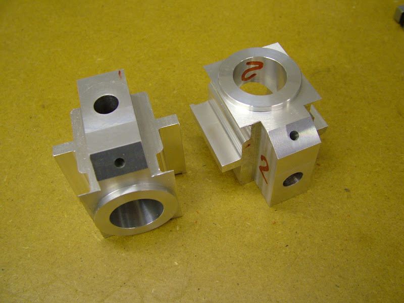
Things will slow down a little now as the set ups get a little more complex - that constant nag of 'is something being machined away that needs to be kept' is getting a stronger by the op.
Jason - I finally managed to load a snipping tool and make it work ;D
Regards for now - Ramon
Had a good days milling today however but still not got to the crux of the matter in dealing with that rear end but that's not far away now. The camera I have been using for all of these shots - the little Nikon Coolpix 2000 - appears to be begining to fade , some of the images taken yesterday turning out quite dark and it's very slow between shots. Shame really it's been a great little camera for this purpose. Fortunately theres a far less used Fuji languishing in the drawer that can now be pressed into service.
Despite that here's a few pics of the latest progress............
Reclaiming the case began with making an insert like a thick washer about .5mm thicker than required. The hole (in the insert) was bored to 9.95 and the outer rim cut at a half degree angle so that as it would be pressed into it's recess (and Loctited) hopefully the join would be near invisible. Once this was done yet another expanding mandrel was turned up - I just love making these things, they work so well

This held the case with less than .01TIR and the recess was then bored until the back face just cleaned up and the insert would just enter. As with pinning the recess edge was not deburred. Held on a previously turned spigot the insert was pressed in using the tailstock.

Once the Loctite had cured this was faced back to the original depth then the case set up as before for boring out for the liner. Finally by using the chucking reamer by hand from the outer end that .05 left in the bore of the insert was reamed inline with the original bore. The reclaimed #1 is on the left

Back to square one rough milling the outer faces could begin and this was done in the vise with packing to protect that finish turned top face. First the rear end was reduced each side to a 'reasonable' finish as this was to be used for subsequent setting up then the sides above and below the lugs were taken out to within 1mm of finished size


Now the finishing could begin so first off was to mount that spigot previously machined on an angle plate and square it up on the mill. The mill spindle was centred accurately about the centre line of the spigot

The case was set square to the table via that reduced width then the lower (actual - the top in the shot) face was then milled as a datum and the lower faces of the lugs and crankcase width finished off to size

The case was rotated for the sides above the lugs and the lugs themselves to be finished this time using an end mill which had had the corners radiused. The top edges of the main body sides were then milled before setting up again to radius the edges with a corner rounding cutter ......


.....and this is how they look tonight..


Things will slow down a little now as the set ups get a little more complex - that constant nag of 'is something being machined away that needs to be kept' is getting a stronger by the op.
Jason - I finally managed to load a snipping tool and make it work ;D
Regards for now - Ramon
Nicely recovered, that camera can't be too bad as I can still see the joint in a couple of the photos 
J
J

$99.99
AHS Outdoor Wood Boiler Yearly Maintenance Kit with Water Treatment - ProTech 300 & Test Kit
Alternative Heating & Supplies

$26.89
$34.99
Peachtree Woodworking Supply Bowl Sander Tool Kit w/Dual Bearing Head & Hardwood Handle, 42 Pieces Wood Sander Set, 2 Hook & Loop Sanding Disc Sandpaper Assortment, 1/4 Mandrel Bowl Sander
Peachtree Woodworking Supply Inc

$599.00
$649.00
FoxAlien Masuter Pro CNC Router Machine, Upgraded 3-Axis Engraving All-Metal Milling Machine for Wood Acrylic MDF Nylon Carving Cutting
FoxAlien Official

$19.15
$29.95
Competition Engine Building: Advanced Engine Design and Assembly Techniques (Pro Series)
MBC Inc.

$49.95
$55.99
DjuiinoStar Hot Air Stirling Engine Assembly Kit: Spend 30 Minutes to Build Your Own Stirling Engine
djuiinostar
![DreamPlan Home Design and Landscaping Software Free for Windows [PC Download]](https://m.media-amazon.com/images/I/51kvZH2dVLL._SL500_.jpg)
$0.00
DreamPlan Home Design and Landscaping Software Free for Windows [PC Download]
Amazon.com Services LLC

$45.99
Sunnytech Mini Hot Air Stirling Engine Motor Model Educational Toy Kits Electricity HA001
stirlingtechonline

$36.94
$49.99
Becker CAD 12 3D - professional CAD software for 2D + 3D design and modelling - for 3 PCs - 100% compatible with AutoCAD
momox Shop
- Joined
- Jan 30, 2011
- Messages
- 365
- Reaction score
- 72
Err... I don't think so Jason - I think what you may be seeing is a turning mark - the join line bisects the corners of the top bore step, I notice though theres a tiny ridge in the corner of that step probably caused by a bit of swarf getting in between the dead stop when boring to depth - theres a fair bit of it around you now :big:
Re the camera - last pics taken with it were the first three of the last post. I had a series of very dark background images as in the second image but what has really changed is the time it takes to open from switching on - a long delay before anything happens - and also the time between taking a pic and ready for the next, big delay there too, and yes the battery is charged
Question for you - As said have got the Snippy tool uploaded and have got a section of an image 'clipped' and saved into Word. - How do you get just the image posted here and not the whole blank surround? ???
Ramon
- Joined
- Jan 30, 2011
- Messages
- 365
- Reaction score
- 72
Aha - belay that last request Jim lad 
I'm not quite sure how I arrived at it but treat this as a test.
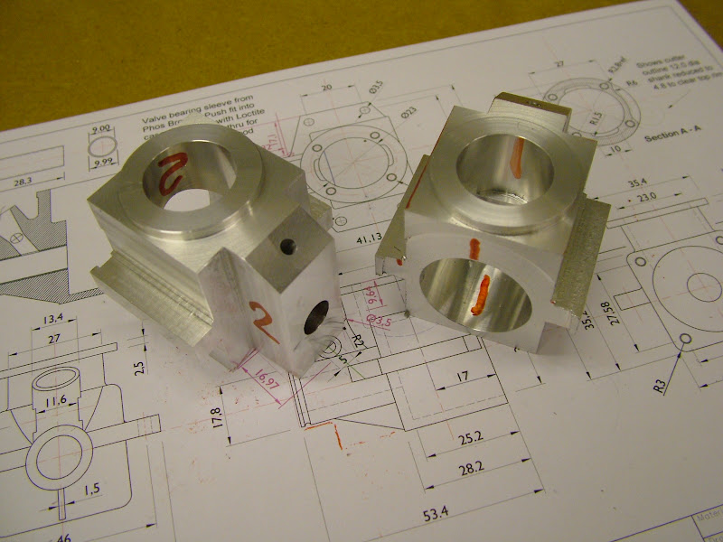
Those who might have an interest may have noticed these Magenta coloured additions to the drawing.
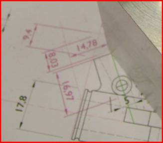
They are not modifications but are for setting up for machining. Now it's time for those next ops - back later
Ramon
I'm not quite sure how I arrived at it but treat this as a test.
Those who might have an interest may have noticed these Magenta coloured additions to the drawing.

They are not modifications but are for setting up for machining. Now it's time for those next ops - back later
Ramon
Not quite sure how you got there but when I snip something when the window pops back up after snipping I just go file, save as and it will save it as a .jpg which you just treat like any other image.
J
J
- Joined
- Jan 30, 2011
- Messages
- 365
- Reaction score
- 72
Hi Guy's - I had hoped to be a little further on by now but having hit a couple of snags as things developed which, though so far overcome, and, coupled with the usual external factors that do their best to prevent access to the 'Ole Comfort Zone' at times when that's were you'd rather be has tempered progress a tad :
However heres few more pics of the progress and other bits and pieces to bring it up todate to tonight..........
That expanding mandrel was set up using the four jaw - I don't usually do that prefering to make a new one to ensure accuracy (not so much concentrically but axially) but this worked out fine. The diameter at the end of the valve housing was defined plus .5mm to give a good indicator of whats to come off - or more importantly what to leave on - and to try to establish that rear angle of the intake tube. The overhang on the mandrel was a bit too much for that and there was quite a bit of chatter - this will have to be sorted a bit later
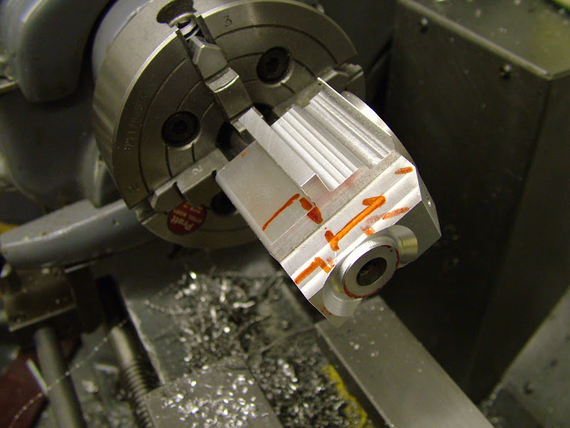
Using the vise on the mill the bolt holes for the front housing and cylinder were drilled using coordinates then some of the waste around that rear end was milled away leaving about a mil on
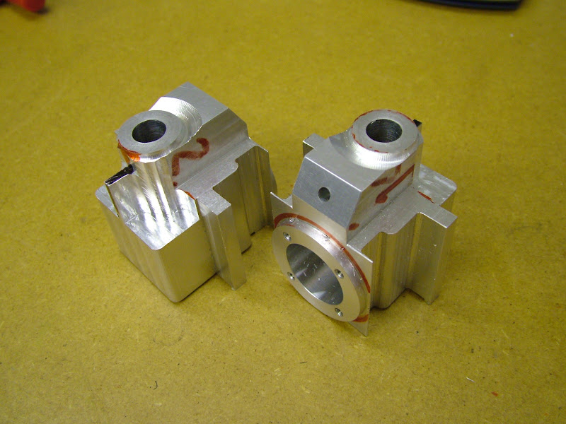
I felt the next area that needed to be tackled was rounding the top so first a cutter required making. A blank long enough for two was milled, parted off and heat treated without tempering. I have put quench in oil on the drawing which is what I usually do and did the first as such but it didn't seem to have that glass hardness so the second one was done in water.
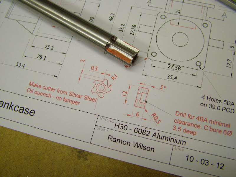
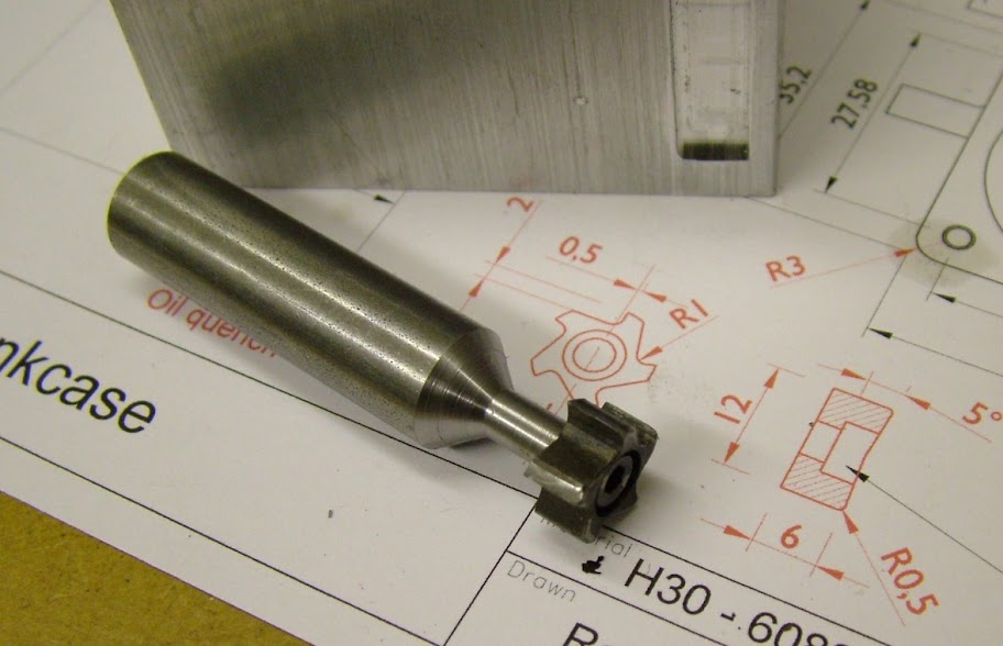
The cutter was backed off by hand using a needle file and after treatment bolted to its mandrel with a 4BA bolt and the cutting edges stoned. The block in the background was used to do a test cut
Looking at what was available for the next ops it was clear that some extraneous work on the workholding front was going to have to be done....
An ali block was shaped up to hold the case at the 60degree angle for doing the venturi and a plate faced up and slotted so this can be centred either on the faceplate or rotary table
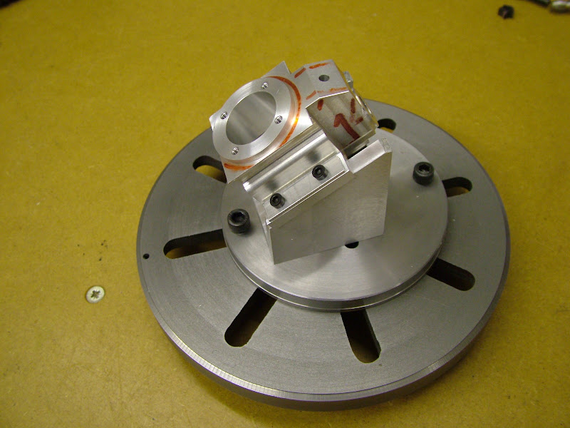
Then this adjustable fixture - made many years ago for holding crankcases for boring out the main bearing sleeve - was modified to use on the R/T.
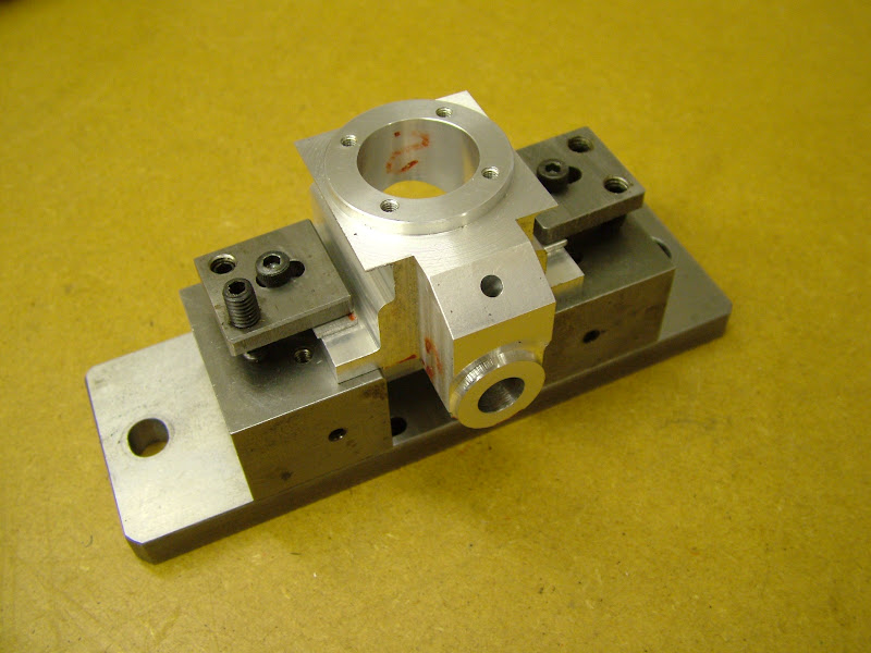
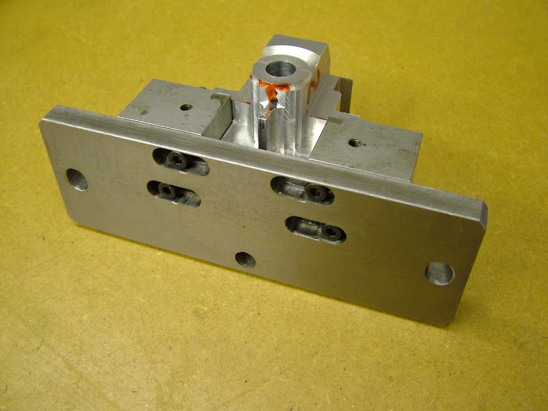
Then it was time to get going again....
After centering the R/T to the spindle the fixture, with the #1 case securely clamped in, was set up and the bore carefully centred before tightening it down to the R/T.
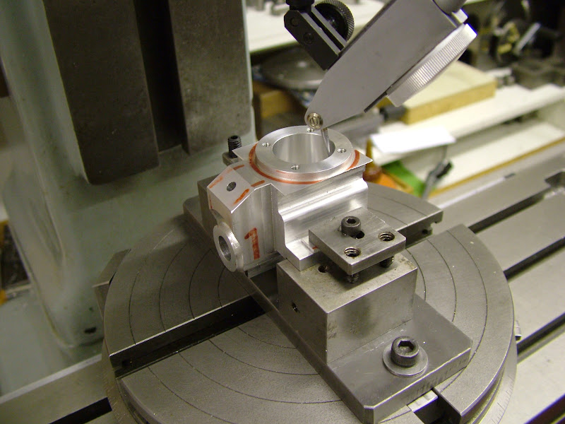
Using a 4mm FC3 chamfered on the corners milling began by removing the waste around the top paying care not to go too deep over the rear intake tube. It was here that it was noticed that the detail on the drawing for the cutter diameters is in error due to the fact that the outer top profile wasn't drawn over the view - we need a smiley for 'sod it' - the reduced part of the shank is not enough to allow the 12mm cutter to get in. The shank was set up and the reduced portion taken down to 3.6mm but it disintegrated as soon as the bolt was tightened. Hmmm
After a good look it was 'Compromise' time : - Top was reduced to 35dia and that recessed diameter increased to 28.
a new cutter shank was turned this time using a 2.5mm caphead - only one I could find but ones enough and it ended the day like this
Before beginning this thread it was assumed that the only way drawings could be put up was to upload them. Obviously this is not a good idea if they are not proven! So, the drawings will be updated as work progresses and having now got the gist of snipping will wait until the case is finished before putting the final version up here rather than upload them - unless that is any one would like to access them as a PDF. We all make mistakes, but I confess I don't like making them but then again this is a 'first off'
Hope this is still of interest to you
regards - Ramon
However heres few more pics of the progress and other bits and pieces to bring it up todate to tonight..........
That expanding mandrel was set up using the four jaw - I don't usually do that prefering to make a new one to ensure accuracy (not so much concentrically but axially) but this worked out fine. The diameter at the end of the valve housing was defined plus .5mm to give a good indicator of whats to come off - or more importantly what to leave on - and to try to establish that rear angle of the intake tube. The overhang on the mandrel was a bit too much for that and there was quite a bit of chatter - this will have to be sorted a bit later

Using the vise on the mill the bolt holes for the front housing and cylinder were drilled using coordinates then some of the waste around that rear end was milled away leaving about a mil on

I felt the next area that needed to be tackled was rounding the top so first a cutter required making. A blank long enough for two was milled, parted off and heat treated without tempering. I have put quench in oil on the drawing which is what I usually do and did the first as such but it didn't seem to have that glass hardness so the second one was done in water.

The cutter was backed off by hand using a needle file and after treatment bolted to its mandrel with a 4BA bolt and the cutting edges stoned. The block in the background was used to do a test cut

Looking at what was available for the next ops it was clear that some extraneous work on the workholding front was going to have to be done....
An ali block was shaped up to hold the case at the 60degree angle for doing the venturi and a plate faced up and slotted so this can be centred either on the faceplate or rotary table

Then this adjustable fixture - made many years ago for holding crankcases for boring out the main bearing sleeve - was modified to use on the R/T.


Then it was time to get going again....
After centering the R/T to the spindle the fixture, with the #1 case securely clamped in, was set up and the bore carefully centred before tightening it down to the R/T.

Using a 4mm FC3 chamfered on the corners milling began by removing the waste around the top paying care not to go too deep over the rear intake tube. It was here that it was noticed that the detail on the drawing for the cutter diameters is in error due to the fact that the outer top profile wasn't drawn over the view - we need a smiley for 'sod it' - the reduced part of the shank is not enough to allow the 12mm cutter to get in. The shank was set up and the reduced portion taken down to 3.6mm but it disintegrated as soon as the bolt was tightened. Hmmm
After a good look it was 'Compromise' time :
a new cutter shank was turned this time using a 2.5mm caphead - only one I could find but ones enough

Before beginning this thread it was assumed that the only way drawings could be put up was to upload them. Obviously this is not a good idea if they are not proven! So, the drawings will be updated as work progresses and having now got the gist of snipping will wait until the case is finished before putting the final version up here rather than upload them - unless that is any one would like to access them as a PDF. We all make mistakes, but I confess I don't like making them but then again this is a 'first off'
Hope this is still of interest to you
regards - Ramon
- Joined
- Jan 30, 2011
- Messages
- 365
- Reaction score
- 72
Hi again, I have just noticed that most of the images are blank on the second page. I don't know why this should be - the images in questionare all still in my web album but last night I noticed that that had several images duplicated and placed in to the album at random - I deleted them so that may be the problem - what ever I will try to fix the probem but "not tonight Josephine" I need my beauty sleep 
- Joined
- Jan 30, 2011
- Messages
- 365
- Reaction score
- 72
Pics duly fixed but what a pain - hope I don't have to do that again. Don't know what caused it but definitely an aberation with Picasa :
Had another good days milling but it is slow going - as each op is passed however the 'anxiety' level increases - had a mishap today on case #1 that caused a good flutter Well pleased with how the home made cutter had worked on the reccesses it occurred that it would be an opportune set up to do the transfer pockets. Set the stops on the RT then carefully selecting 'mind in neutral' mode moved over to take a trial cut - 90 degress out of phase - Aaaagh
  oh:
oh:  oh:
oh:
'Fortunately' it's shallow radially and not too deep but is fundementally unrecoverable other than to open up the bore for the liner which is not a 'preferred option' so it will have to stay. It won't have any effect on performance and won't show once assembled so it isn't as bad as first thought and it is after all the test or set up piece - things could still go pear shape as yet (and no doubt will : ) but it would be nice if there were two useable cases at the end.
A few more pics of progress - it's still looking bloody ugly but a case is gradually beginning to appear.....
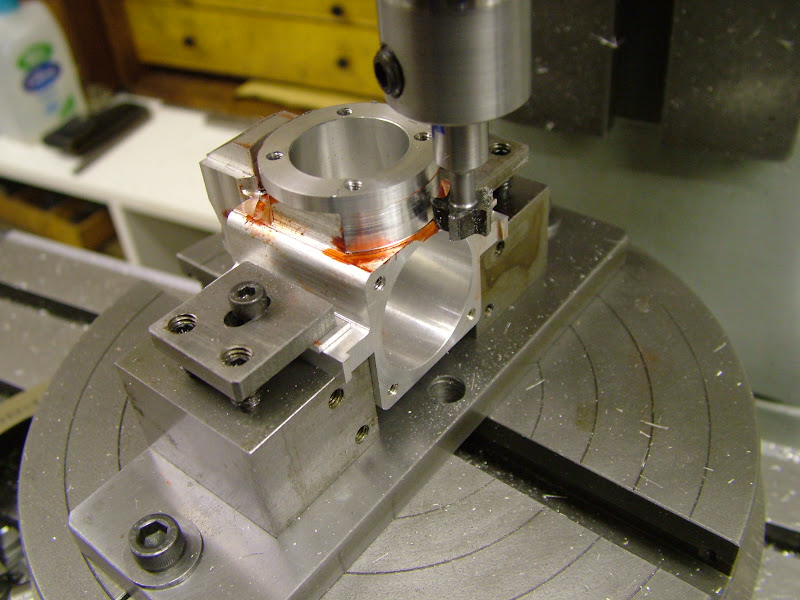
Cutting the front rebate. Despite the straight tooth form the finish was reasonable and following a tentative trial with a needle file should clean up without too much work

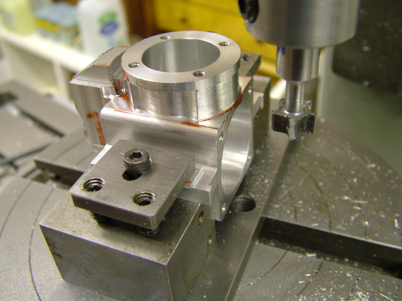
Those side reccesses were tackled next - just on depth the shank of the cutter just rubbed the top rim but there's a .1mm allowance left for turning so that should dissappear
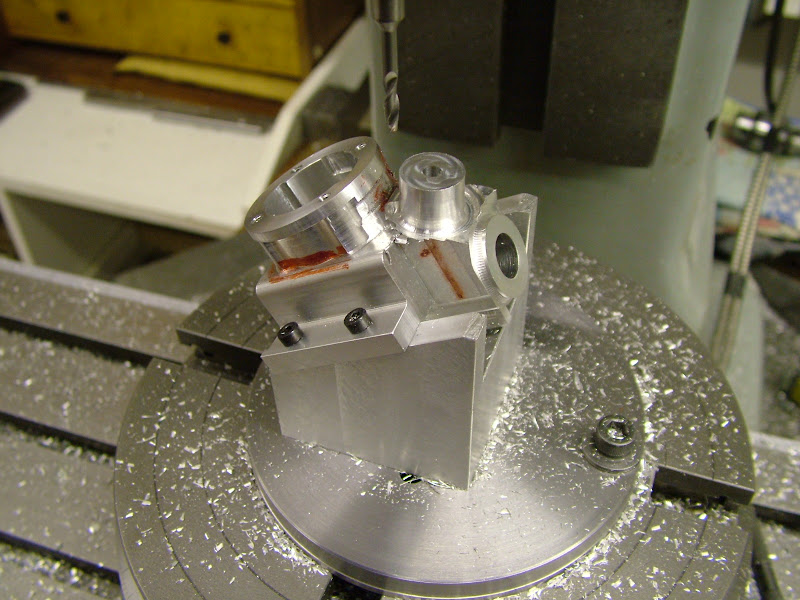
Another, smaller diameter cutter will be required to finish the rebate at the rear but first the material around the intake tube needed removing
And this is how they finished tonight -
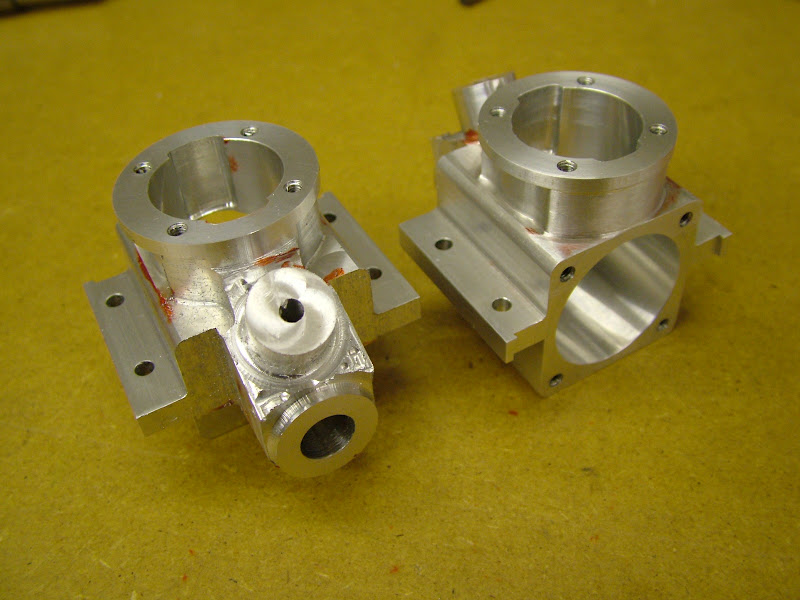
- as said still not a pretty sight but getting there slowly
I hope this will be of use to someone - it would be nice to hear if it is or from anyone else into small I/Cs
Regards for now - Ramon
Had another good days milling but it is slow going - as each op is passed however the 'anxiety' level increases - had a mishap today on case #1 that caused a good flutter
'Fortunately' it's shallow radially and not too deep but is fundementally unrecoverable other than to open up the bore for the liner which is not a 'preferred option' so it will have to stay. It won't have any effect on performance and won't show once assembled so it isn't as bad as first thought and it is after all the test or set up piece - things could still go pear shape as yet (and no doubt will :
A few more pics of progress - it's still looking bloody ugly but a case is gradually beginning to appear.....
Cutting the front rebate. Despite the straight tooth form the finish was reasonable and following a tentative trial with a needle file should clean up without too much work

Those side reccesses were tackled next - just on depth the shank of the cutter just rubbed the top rim but there's a .1mm allowance left for turning so that should dissappear

Another, smaller diameter cutter will be required to finish the rebate at the rear but first the material around the intake tube needed removing

And this is how they finished tonight -

- as said still not a pretty sight but getting there slowly
I hope this will be of use to someone - it would be nice to hear if it is or from anyone else into small I/Cs
Regards for now - Ramon
Very interesting piece of machining, much more complex than most things you would find in a production environment. Without seeing this kind of sculpting take place, it is difficult for me to visualise that it is possible, so my horizons are expanding as is the body of things I can't do ! Ramon, I have spent quite a while going backwards and forwards through your process and appreciate the time you have taken to record it.
Jan
Jan
Ramon, the build looks fantastic. I love the idea of scaling old engine designs.
This sort of work was only used in manual machining if it was absolutely unavoidable. Today, anything is possible with multi axis CNC. www.mintor.net is one example of a rather large two stroke engine machined from solid. There are quite a few more on the market.
Greg
ProdEng said:Very interesting piece of machining, much more complex than most things you would find in a production environment.
This sort of work was only used in manual machining if it was absolutely unavoidable. Today, anything is possible with multi axis CNC. www.mintor.net is one example of a rather large two stroke engine machined from solid. There are quite a few more on the market.
Greg
As my friend Rollie of "Rollies Dad's method of lathe alignment" fame has said. When you build a model such as this, you build it about 3 times. Two of the "times" are all the fixtures you make to make the parts. He often brings the box of fixtures for a model engine along to the show to demonstraight this point. It is just part of the fun.
Dave
Dave
- Joined
- Jan 30, 2011
- Messages
- 365
- Reaction score
- 72
Hi Guy's - good to hear from someone  Nice to hear it's of interest Jim and thanks for your appreciation Jan
You're right about fixturing Dave it can add considerably to a build though so far on these small I/C engines it's been kept at a minimum. I try not to make too many jigs either if I can help it though I did make a simple drill jig for the backplate/front housing screws on the Eta's. I have a Bentley BR2 well underway (for far too long but that's another story : ) and the tooling, jigs and fixtures for that add up to a considerable amount of time and work on top of the parts themselves. Like your friend, on the rare occasion when it does get shown there appears as much interest in the 'extras' as the model parts
Greg, scaling the engines so far has been a very pleasurable exercise and they have all run well. Are you making anything at the moment? I have several ideas for others but whether they materialise or not remains to be seen but it's nice to dream. I don't intend to fit any of them in a model though - the desire to build and fly no longer has the intense attraction it once did. As for CNC - well as much as I would love the facility I don't think I could cope with the learning phase all over again. I ran a Haas machining centre for the last few years at work - I can't even remember the first line of code - but coupled with todays CAM software (I was never so lucky!) it would make short work of this that's for sure.
Nothing much happened to day - had an old friend visit for most of the morning which took care of that and when I set the spigot onto the chuck plate for mounting on the R/T I found the chuck plate had a run out in it so time has been spent putting that right - couple that with 'garden distraction' for a few of hours and that's the day gone
Oh well - "Maybe tomorrow Jack"
Regards for now - Ramon
You're right about fixturing Dave it can add considerably to a build though so far on these small I/C engines it's been kept at a minimum. I try not to make too many jigs either if I can help it though I did make a simple drill jig for the backplate/front housing screws on the Eta's. I have a Bentley BR2 well underway (for far too long but that's another story :
Greg, scaling the engines so far has been a very pleasurable exercise and they have all run well. Are you making anything at the moment? I have several ideas for others but whether they materialise or not remains to be seen but it's nice to dream. I don't intend to fit any of them in a model though - the desire to build and fly no longer has the intense attraction it once did. As for CNC - well as much as I would love the facility I don't think I could cope with the learning phase all over again. I ran a Haas machining centre for the last few years at work - I can't even remember the first line of code - but coupled with todays CAM software (I was never so lucky!) it would make short work of this that's for sure.
Nothing much happened to day - had an old friend visit for most of the morning which took care of that and when I set the spigot onto the chuck plate for mounting on the R/T I found the chuck plate had a run out in it so time has been spent putting that right - couple that with 'garden distraction' for a few of hours and that's the day gone
Oh well - "Maybe tomorrow Jack"
Regards for now - Ramon
Similar threads
- Replies
- 18
- Views
- 9K
- Replies
- 3
- Views
- 3K
- Replies
- 172
- Views
- 85K


