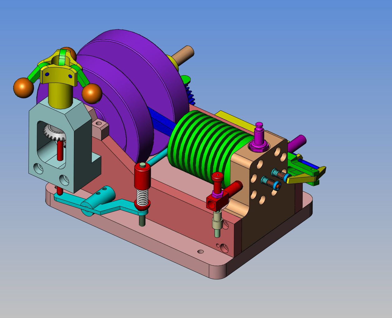
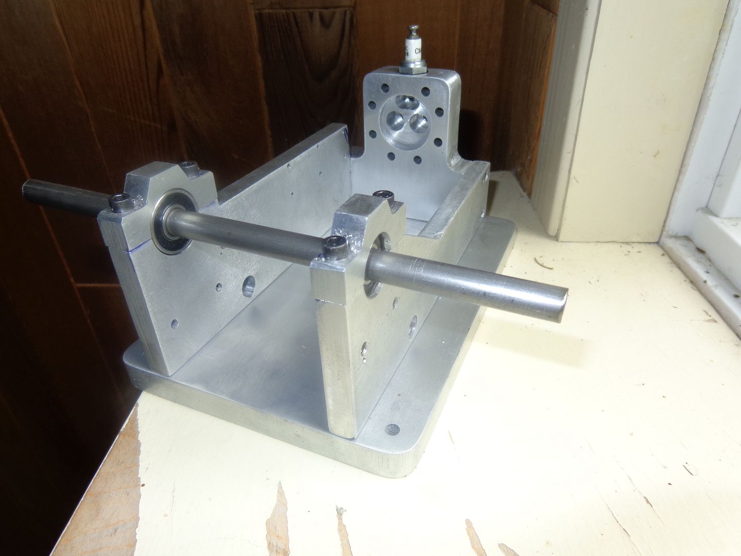
I just discovered a mistake. And for once its not mine!!! The bearings that I bought for the crankshaft were supposedly 3/8" inner diameter. After I took the sideplate out of the milling machine and installed the bearing, I went to fit a piece of shaft in the bearing, and Whoa Nellie----The damned bearing is 5/16" i.d.!!! I checked on the bearing website and there is a bearing with the same outer diameter and thickness, with a 3/8" bore, but its a #1606, not a 1605 as they gave me at the bearing supply house. I will be speaking to them, first thing tomorrow morning!!!
You are using an out of date browser. It may not display this or other websites correctly.
You should upgrade or use an alternative browser.
You should upgrade or use an alternative browser.
Rupnow i.c. Engine with governor
- Thread starter Brian Rupnow
- Start date

Help Support Home Model Engine Machinist Forum:
This site may earn a commission from merchant affiliate
links, including eBay, Amazon, and others.
canadianhorsepower
Well-Known Member
- Joined
- Oct 22, 2011
- Messages
- 1,671
- Reaction score
- 324
I just discovered a mistake. And for once its not mine!!! The bearings that I bought for the crankshaft were supposedly 3/8" inner diameter. After I took the sideplate out of the milling machine and installed the bearing, I went to fit a piece of shaft in the bearing, and Whoa Nellie----The damned bearing is 5/16" i.d.!!! I checked on the bearing website and there is a bearing with the same outer diameter and thickness, with a 3/8" bore, but its a #1606, not a 1605 as they gave me at the bearing supply house. I will be speaking to them, first thing tomorrow morning!!!
Brian , I would go slow on this one. Why?? you or me got the wrong boxing
not really the wright parts in the box. Here are a few pictures of my bearing and number showing that a 1605 is the proper dimension:wall:


Cogsy
Well-Known Member
Ausdier--The bearings are .3125" wide with a .375" center bore and a .9062" outer diameter
I don't know what bearing you've actually got there Luc, the OD doesn't match a 1605 or a 1606. Proper dimensions for a 1606 are as Brian posted, but a 1605 has the same .9062 OD just with a 5/16" bore.
I don't have my imperial bearing books anymore, so I can't identify what you've got, but it's not right.
Thanks for the links JW, I also like http://www.traceparts.com/
Also thanks Brian but I don't think I have the skill or the machines to make one of these for real so I will live in my virtual world for the time being.
Cheers.
Also thanks Brian but I don't think I have the skill or the machines to make one of these for real so I will live in my virtual world for the time being.
Cheers.
Ausdier--Too bad, I wish you could have joined us. I guess Australia's honour is going to be upheld by Cogsy!!!
canadianhorsepower
Well-Known Member
- Joined
- Oct 22, 2011
- Messages
- 1,671
- Reaction score
- 324
+Luc, the OD doesn't match a 1605 or a 1606. Proper dimensions for a 1606 are as Brian posted, but a 1605 has the same .9062 OD just with a 5/16" bore.
Cogsy,
thanks for bringing the outside diameter to my attention. I was sitting in my office with the second bearing in my hand and mesure it had the prorper OD
that boxed Brian's bearing that boxe mine
I'll go and change them for 1606
Last edited:

$29.95
Competition Engine Building: Advanced Engine Design and Assembly Techniques (Pro Series)
Amazon.com Services LLC
![DreamPlan Home Design and Landscaping Software Free for Windows [PC Download]](https://m.media-amazon.com/images/I/51kvZH2dVLL._SL500_.jpg)
$0.00
DreamPlan Home Design and Landscaping Software Free for Windows [PC Download]
Amazon.com Services LLC

$99.99
AHS Outdoor Wood Boiler Yearly Maintenance Kit with Water Treatment - ProTech 300 & Test Kit
Alternative Heating & Supplies

$94.99
$109.99
AHS Woodmaster 4400 Maintenance Kit for Outdoor Wood Boiler Treatment
Alternative Heating & Supplies

$40.02
$49.99
Becker CAD 12 3D - professional CAD software for 2D + 3D design and modelling - for 3 PCs - 100% compatible with AutoCAD
momox Shop

$39.99
$49.99
Sunnytech Low Temperature Stirling Engine Motor Steam Heat Education Model Toy Kit For mechanical skills (LT001)
stirlingtechonline

$45.99
Sunnytech Mini Hot Air Stirling Engine Motor Model Educational Toy Kits Electricity HA001
stirlingtechonline

$89.99
Outdoor Wood Boiler Water Treatment Rust Inhibitor- AmTech 300 & Test Kit
Alternative Heating & Supplies

$24.99
$34.99
Bowl Sander Tool Kit w/Dual Bearing Head & Hardwood Handle | 42PC Wood Sander Set | 2" Hook & Loop Sanding Disc Sandpaper Assortment | 1/4" Mandrel Bowl Sander for Woodturning | Wood Lathe Tools
Peachtree Woodworking Supply Inc

$519.19
$699.00
FoxAlien Masuter Pro CNC Router Machine, Upgraded 3-Axis Engraving All-Metal Milling Machine for Wood Acrylic MDF Nylon Carving Cutting
FoxAlien Official
Cogsy
Well-Known Member
Way to pile on the pressure Brian... 


No worries Luc, I used to sell bearings for many years for large manufacturers (SKF, ***, NTN, etc) and I have never seen a mispackaged bearing before. Looks like you've got the same sort of luck I do
No worries Luc, I used to sell bearings for many years for large manufacturers (SKF, ***, NTN, etc) and I have never seen a mispackaged bearing before. Looks like you've got the same sort of luck I do
I called my bearing guy this morning, all ready to yell his head off. He said "Very Sorry sir--My mistake. They should have been 1606 bearings. I will call right now and have your proper bearings here this afternoon." No harm, No foul. Fortunately everything else about the bearing as in o.d. and thickness remain the same. Luc--I'm sorry for giving bad information. I just read off the outside of the box I have setting here on my reference table, not knowing that the bearing was too small. If your bearings are 3/8" i.d. x 5/16" thick and the only difference is the o.d. then just bore the cavity in the sideplates and bearing caps to suit your bearings if you don't want to return them.---Brian
canadianhorsepower
Well-Known Member
- Joined
- Oct 22, 2011
- Messages
- 1,671
- Reaction score
- 324
Luc--I'm sorry for giving bad information.
Hey Brian
nothing to be sorry about
and in my case it's even worst cause I have to different bearing
a 1604 in a 1605 box
I guess it's god way of punishing me, I was to lazy to go and pick them up
myself........... sent the wife............ now I still have to go
this his what hobby is all about
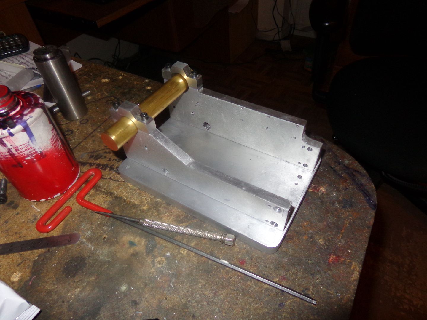
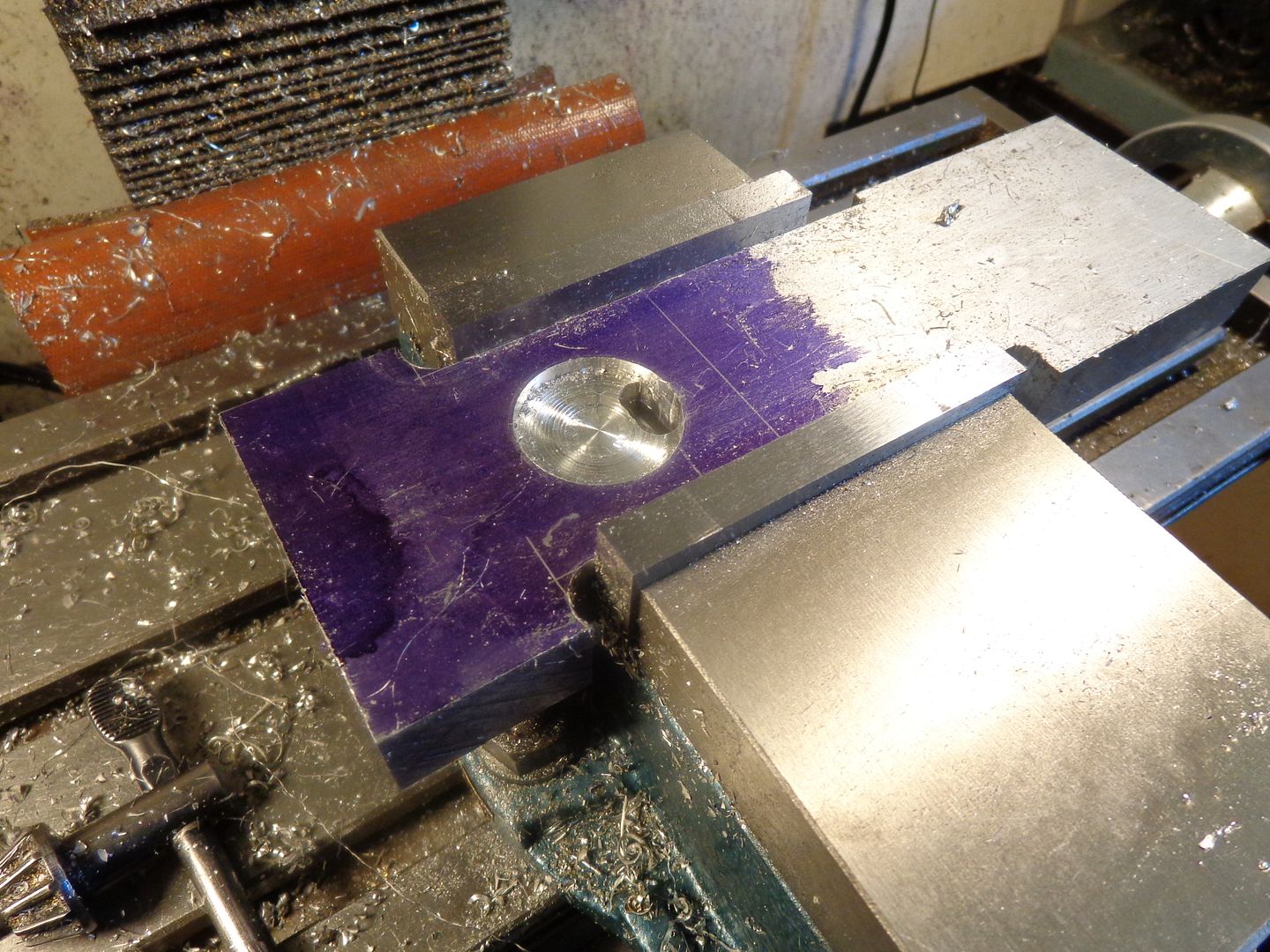
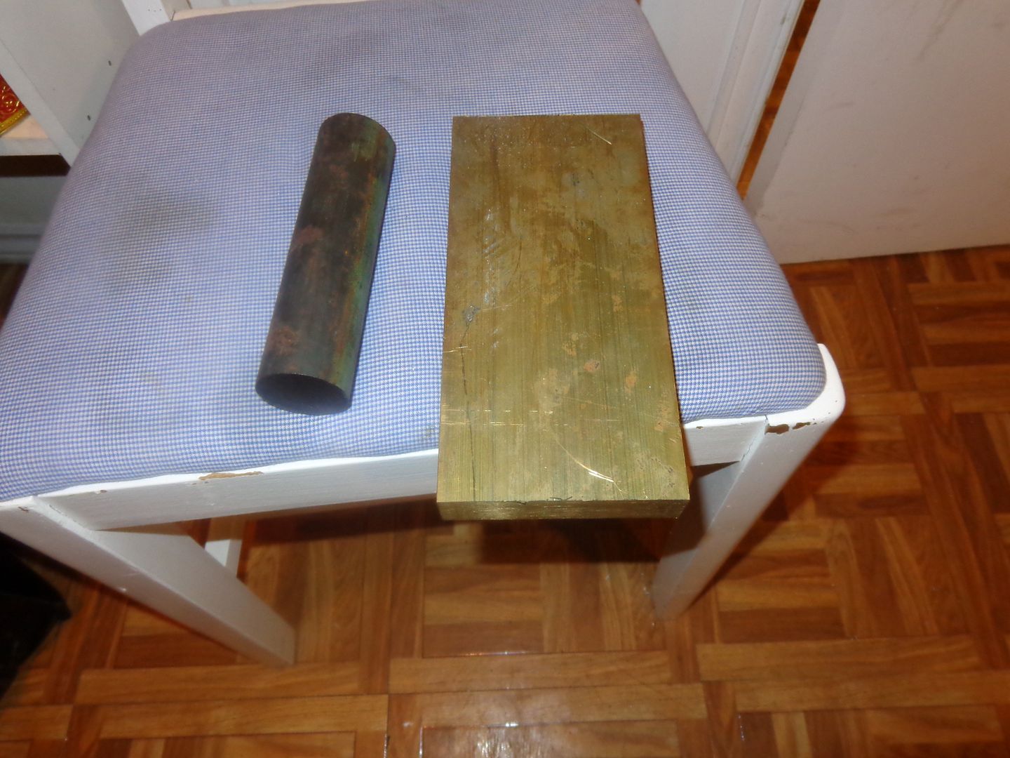
The base and sideplates are finished all except for some cosmetic work. The cylinder head is "In process" on my milling machine. I went down street for supplies and spent a good chunk of the Rupnow fortune on enough brass to make two flywheels and a piece of 1 1/2" diameter grey cast iron for a cylinder. I was beating myself up badly for spending so much money to build "Toys", but when I got home the phone rang and it was a was a customer calling in a panic wanting me to redesign something for them that wasn't working the way they expected it to. (That is GOOD Karma----)


Rivergypsy
Well-Known Member
- Joined
- Oct 15, 2010
- Messages
- 432
- Reaction score
- 222
Ah thats what we like to see - you just can't beat a nice bit of brass 

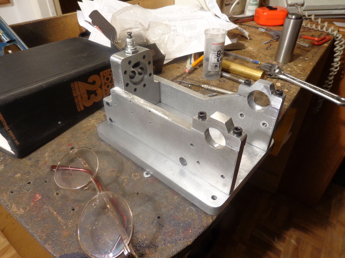
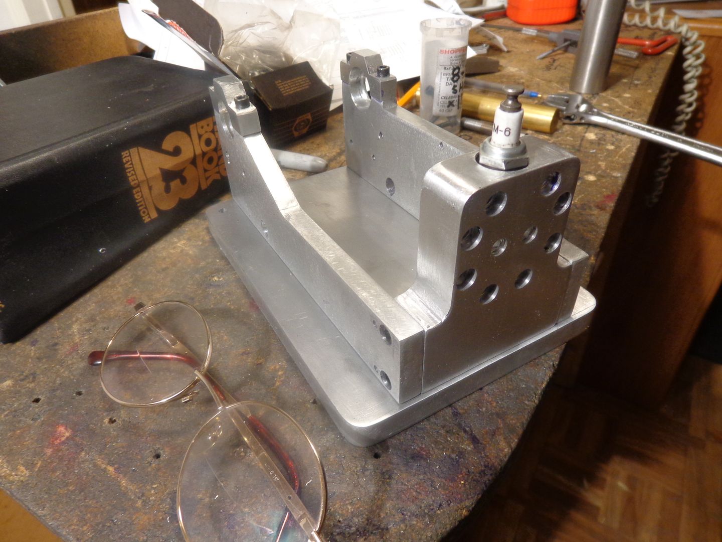
The main frame is finished. All the bolts go in (which is always a good sign). My next thing is going to be the funky crankshaft and flywheels, and I look foreword to it with a mixture of excitement and terror. Exciting because I've never made one like this before, terror for the very same reason. I have to do a bit of research about press fits now. I'm hoping I can buy an undersize reamer for the flywheels and press in the 3/8" cold rolled shafts with no other mechanical lock, other than perhaps a little Loctite which claims to be "for press fits".



Cogsy
Well-Known Member
Just curious as to how you will align the flywheels for a press fit? I've been wondering that ever since I pulled apart my first 2 stroke dirt bike, but now I'm REALLY curious.
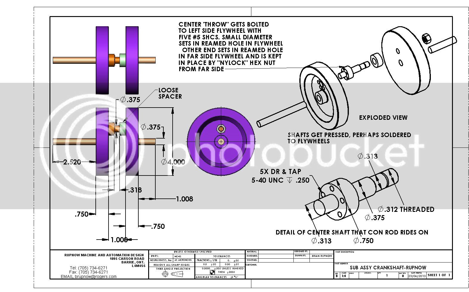 Cogsy--take a close look at the drawing. The 3/8" shafts press fit into the individual flywheel centers. The bolted piece between the flywheels has a 5/16" end on it which is a "close running fit" into a 5/16" hole in the flywheel. to position it, and a ring of bolts to secure it in place. The other end has a 3/8" center diameter for the con rod bearing, then is turned down to 5/16" diameter which is again a "close running fit" into a 5/16" hole in the other flywheel. First piece of 3/8" crankshaft with flywheel and center stub is held in 3 jaw chuck in lathe. Second piece of crankshaft with flywheel only is held in tailstock mounted chuck. This aligns the two pieces of crankshaft. The headstock chuck is rotated until the 5/16" stub on the center piece is lined up with the hole in the second flywheel. They are SLID together (not pressed) until the 3/8" diameter on the center stub is against the side of the second flywheel. Then a nut is screwd onto the center stub and torqued in place . then assembled crankshaft is removed from both chucks.
Last edited:
Good luck. I remember helping my son put a crank like that together in a dirt bike. There are many ways it can go together, only one of which is correct.
I don't think you need the bolted fitting on one end of the rod shaft. Just make it a press fit into each disk. Press it all together, put it between centers, or running in the main bearings, and with a lead hammer whack it around until it runs true. Thats how we got the dirt bike together- and it was the recommended way in the manual
I think you should plan to make truing cut over the 2 disks after they have been pressed onto the shaft ends. Put the end in a 4 jaw and align it very well, then skim the face and rim of the wheel. Now put the true, flat face of the wheel on the mil table and bore the hole for the pin.
On reamers I got a set of over and under reamers for the major fractions from 1/8 to 1/2 from Wholesale Tool several years ago. I has like .374 and .376 Id guess .001 press fit on the shaft might do the job.
Nice project, and very brave to ask 10 guys to follow you, not knowing if its a path to success, or falling off the cliff But I am sure, in the end, you will get there.
I don't think you need the bolted fitting on one end of the rod shaft. Just make it a press fit into each disk. Press it all together, put it between centers, or running in the main bearings, and with a lead hammer whack it around until it runs true. Thats how we got the dirt bike together- and it was the recommended way in the manual
I think you should plan to make truing cut over the 2 disks after they have been pressed onto the shaft ends. Put the end in a 4 jaw and align it very well, then skim the face and rim of the wheel. Now put the true, flat face of the wheel on the mil table and bore the hole for the pin.
On reamers I got a set of over and under reamers for the major fractions from 1/8 to 1/2 from Wholesale Tool several years ago. I has like .374 and .376 Id guess .001 press fit on the shaft might do the job.
Nice project, and very brave to ask 10 guys to follow you, not knowing if its a path to success, or falling off the cliff
Last edited:
Ron--I've made it though 67 years without too many "cliffs". In a best case scenario, I will have a lot of fun with this and 10 other guys will have built a new engine. In a worst case scenario I will have 10 very ugly people out there. Of course, I prefer the happy ending. The only thing I haven't built before is the wonky crankshaft in this engine. And even if that ends up being a total "no goer", the engine can still be made operational with a more conventional crankshaft. I wouldn't be so bold as to say I was "Going boldly where no man has gone before", but it has a bit of that feel to it. I know that a lot of people are going to hang back and watch to see if this engine is a success. There is nothing wrong with caution. So far it seems like its only Luc and I who are getting into this.
canadianhorsepower
Well-Known Member
- Joined
- Oct 22, 2011
- Messages
- 1,671
- Reaction score
- 324
Hey Partner,
I started working on plates today will post pictures soon on my thread.
My question is this...... Is the air cool and water cool have same head configuration. according to the pictures of photo bucket it does not.
For those that worry if your bold:hDe: or me stupid:wall: if everything
and I mean everything is a total lost. It will only create a good reason
to start doing foundry work by melting everything backRof}Rof}Rof}to aluminium stock and start all over.;D
cheers
Luc
Last edited:
I'm 23 so I'm young in the engineering game. I've been in the trade 5 years and hitting "cliffs" is all part of the parcel and I love it. I'm ready and eager to make a start on this engine because its going to be my first one. But I'm on me jolly hols at the mo and can't get started yet  . I've always been one to jump in and get something done its how I learn.
Loving reading this thread, and love the fact that an international community can come together and work together all because one man come up with a fantastic idea. My hat is off to you Brian and your marvellous mind.
Now roll on Thursday when I can get back to my machinery at home and start making some chips for this marvellous engine.
Similar threads
- Replies
- 95
- Views
- 12K
- Replies
- 28
- Views
- 7K


