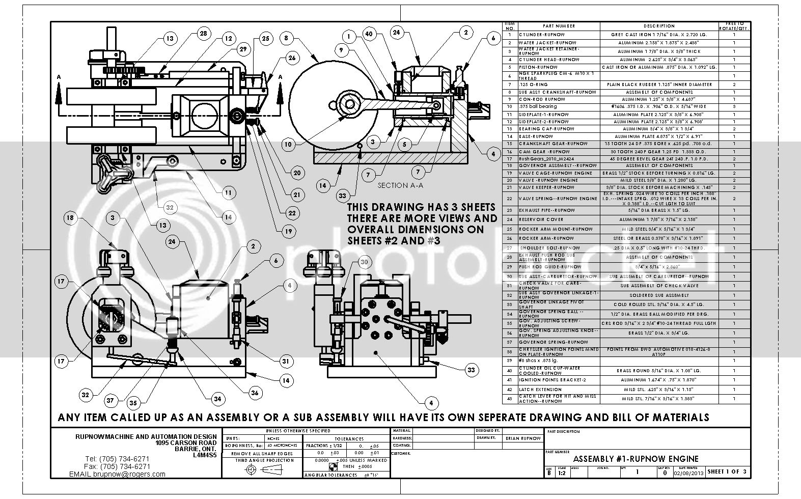
Rupnow i.c. Engine with governor

Home Model Engine Machinist Forum

Help Support Home Model Engine Machinist Forum:

This site may earn a commission from merchant affiliate links, including eBay, Amazon, and others.
Will put the CDI when it comes in and report on Webbie's performance.

7:30am now and at 9:30am mate comes over to pick me up for the airport to Thailand.
Will shop around the automoblie parts shop looking for brand new HT Ignition Coil.
 
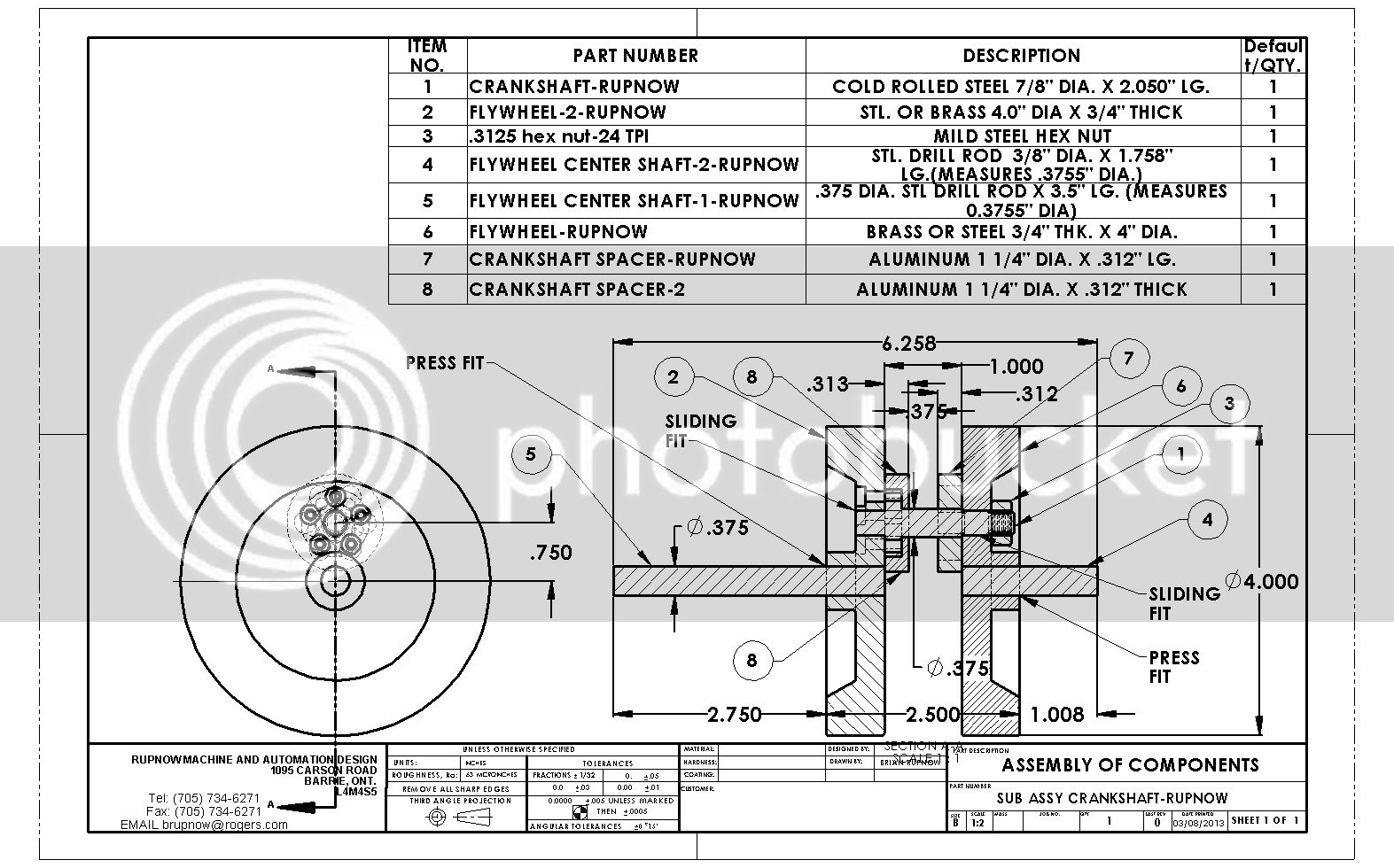
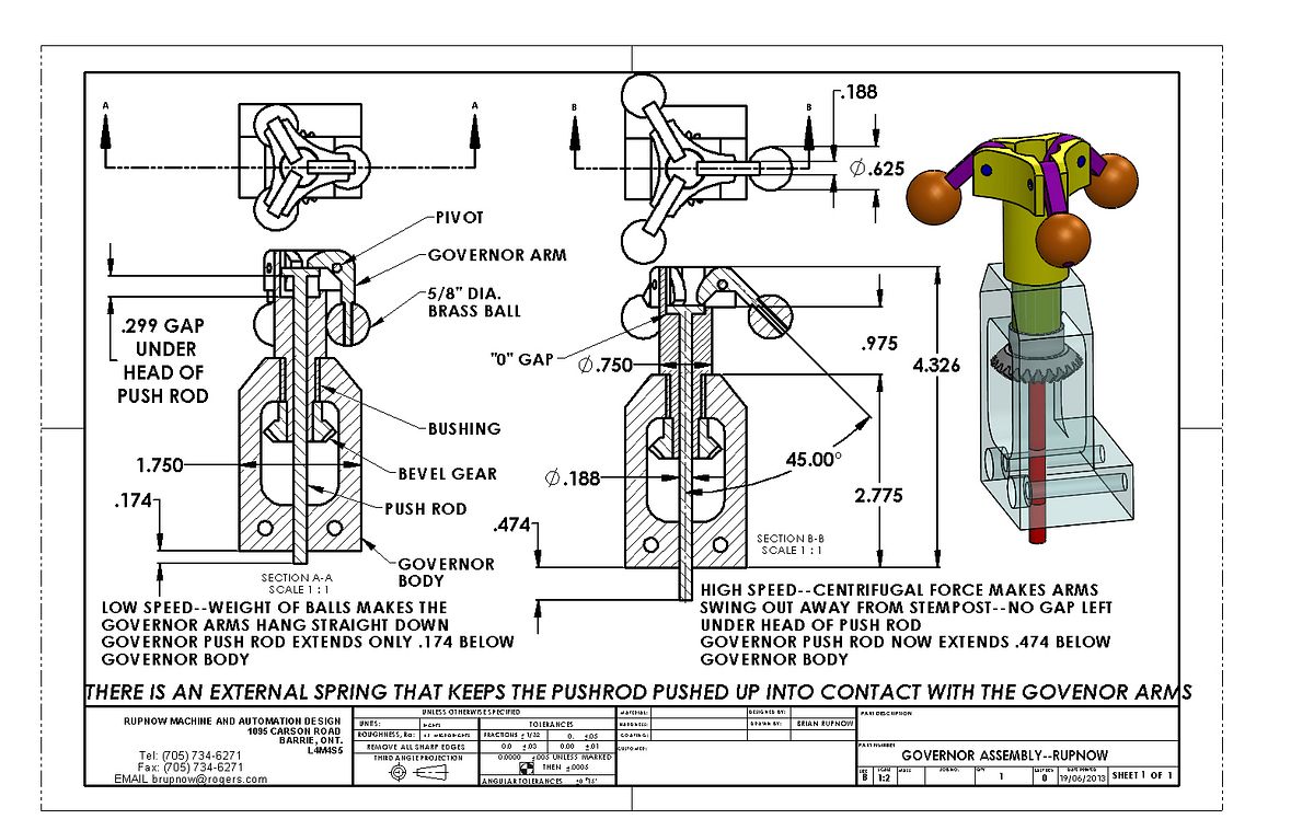
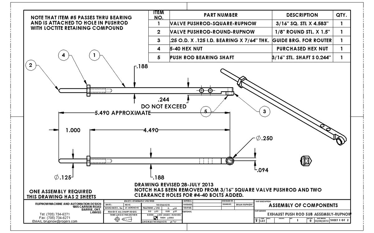
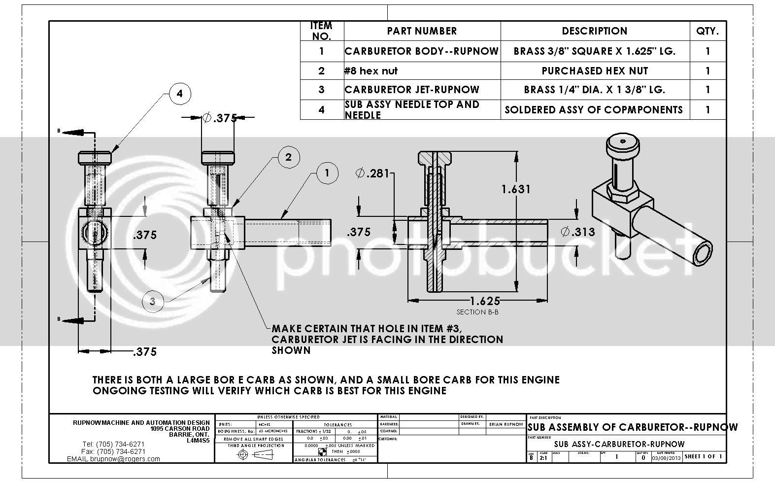
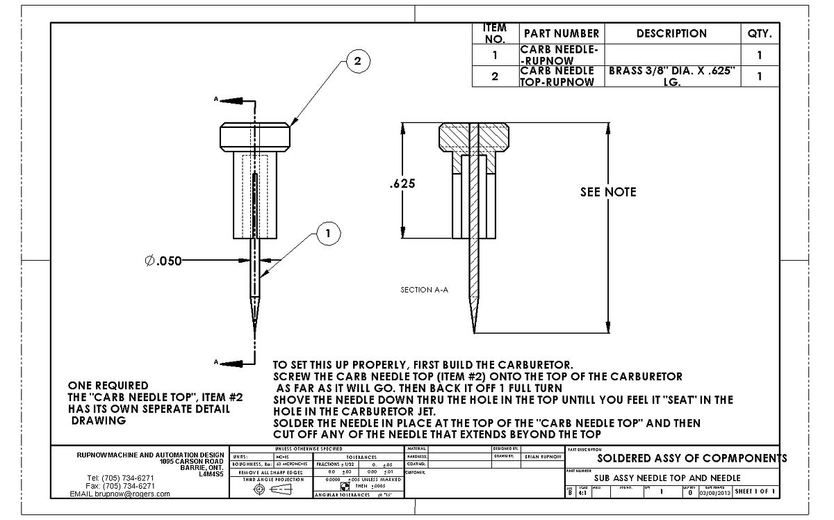
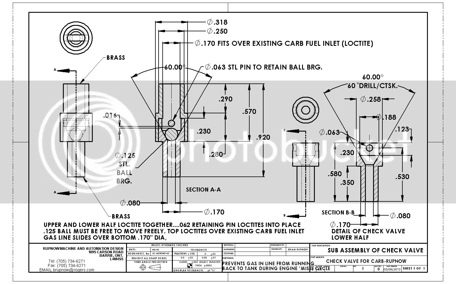
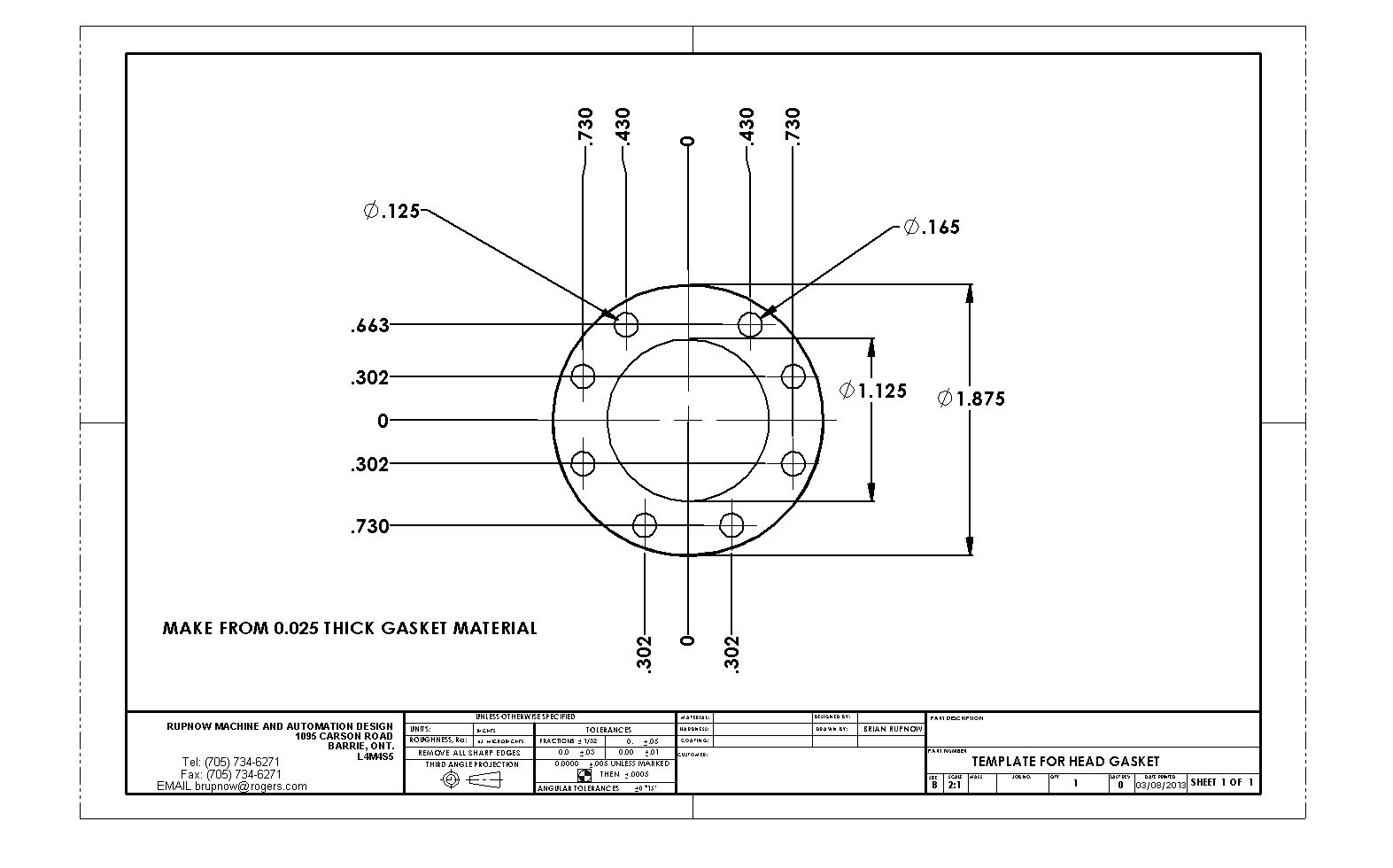
That pretty well covers all of the assembly drawings. I will be pulling all of the pdf files together into an package and posting a link, eventually. I am waiting for my electronic ignition right now, so can't do anything more until it arrives. The engine runs in hit and miss mode as you have all seen in the video I posted. I do have some issues with either carburetion or spark, I'm not certain which at this point. Mechanically, everything seems to be fine, no clearance issued have appeared throughout the build, and the engine turns over very freely with the ball bearings on the crankshaft and connecting rod. If anyone is aware of any missing drawings or information, please let me know.---Brian
 
Thanks Brian

Your drawings look great ... SW sure is nice to work with.:)

Pat H.
 
Thanks Brian for the excellent work on the drawings and design. I had been thinking about a head gasket, but you now have that covered.

Paul.
 
A bit of knowledge about hit and miss carburetors, as I understand them---
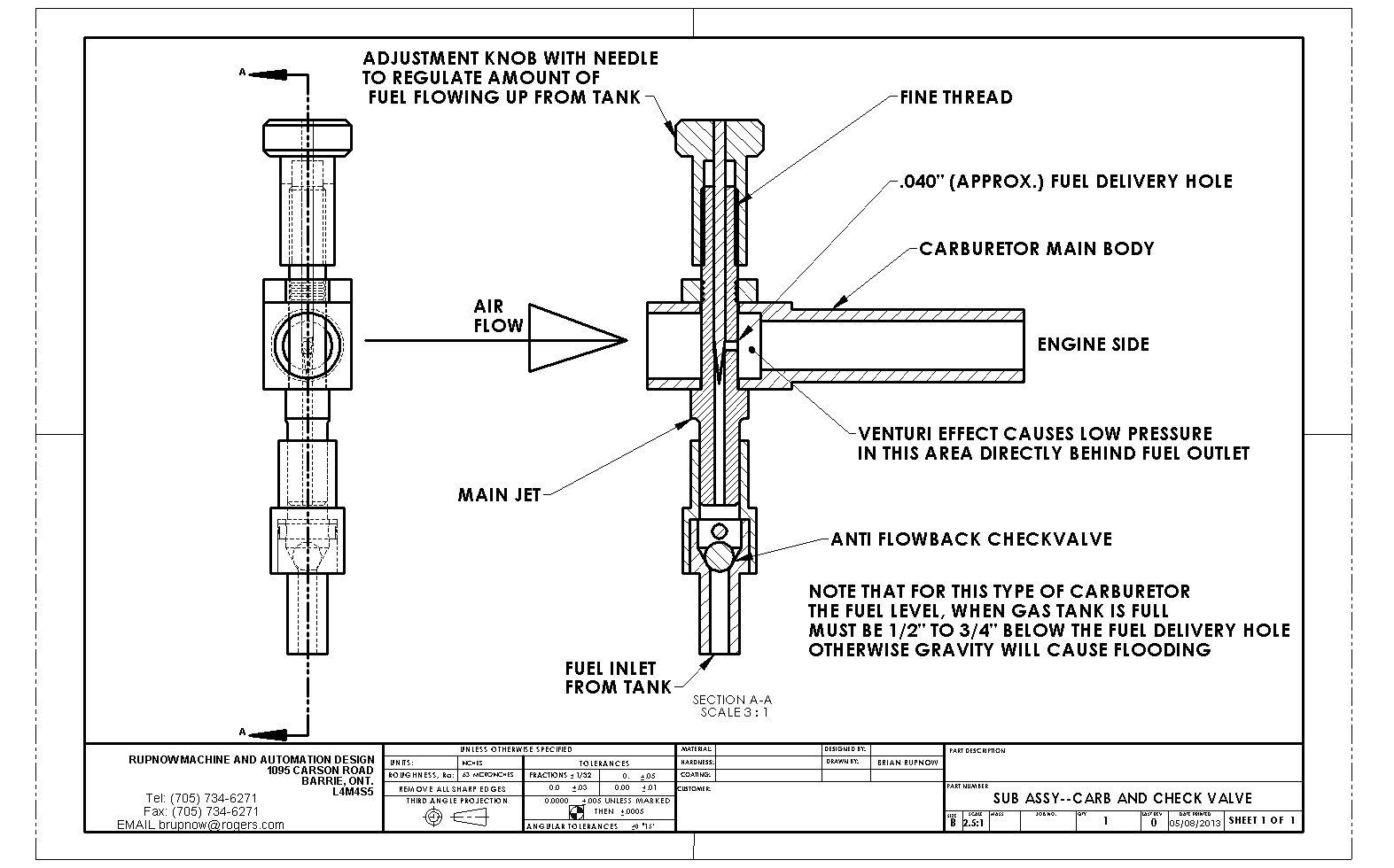
Carburetors for hit and miss engines are a very simple carburetor, consisting of an outer body, a main carburetor central "jet" with an approximate 0.040" hole in it, and a needle valve which varies the amount of fuel allowed to escape from that .040 hole into the air stream. The "suction" required to pull fuel out of that .040" diameter hole into the stream of air flowing thru the main body of the carb is created by the venturi effect in the carburetor. Venturi effect is basically a principle of air movement that says that any time air flowing thru a tube meets a restriction in the tube, a low pressure area will be created at or just behind the obstruction. In the case of a simple hit and miss carburetor, the "'obstruction" that creates the venturi effect is the carburetor jet itself. The low pressure area will be on the engine side of that "obstruction", and that is why the .040" diameter hole faces inward to where the engine is, so that the maximum venturi effect in that area will "suck" the fuel from the carburetor jet.----- Air bleed carburetors are commonly used on engines which have a throttle plate in them. When the throttle opens and venturi induced vacuum drops, the air bleed hole helps keep fuel flowing so the carburetor doesn't stall. Since there is no throttle plate on a hit and miss carburetor, and the hit and miss engine is never ran at an idle, they don't use carburetors with an air bleed hole. Basically, hit and miss carburetors run "wide open" all the time. The speed of the engine is controlled by the strength of the springs that restrain the governors from flying out and preventing the exhaust valve from closing. We want the engine to fire with the largest possible force (carburetor wide open) so that the kinetic energy created will give those big flywheels enough of a "kick" that the engine will immediately fly into miss mode and cycle many times before it fires again.----This is why hit and miss engines have the anti flowback check valve attached directly below the carburetor. The fuel level in the gas tank must be 1/2" to 3/4" below the orifice in the carburetor jet to prevent gravity flooding. When the engine goes into "miss" mode and there is no air being sucked thru the carburetor, the gasoline in the line will immediately fall back to the tank level below the carburetor if there is no check valve. Then when the engine slows enough to fire again, it will have to coast thru one or two more revolutions to let venturi action suck the fuel back up into the carburetor jet. Remember--when the engine is coasting in "miss" mode, the exhaust valve is held open so there is no "suction" created by the piston to suck air in thru the carburetor air inlet, so consequently there is no venturi effect in the carb when the engine is coasting, and no fuel being sucked into the engine. These extra two revolutions required to get fuel back up from the fuel tank level and actually spraying out of the .040" hole in the jet may slow the flywheels down so much that the engine then just stalls out instead of coasting thru one more compression cycle so it can fire again.


View attachment SUB ASSY--CARB AND CHECK VALVE.PDF
 
Last edited:
Brian
Is there a drawing of the wrist pin as I cannot find it.
Its a trick---There is no drawing!!! Many of the plain pieces of cold rolled steel shaft that form pivots, wrist pins, etcetera are not drawn. In the particular part you are asking for, its a piece of 3/16" cold rolled round shaft x 13/16" long.
 
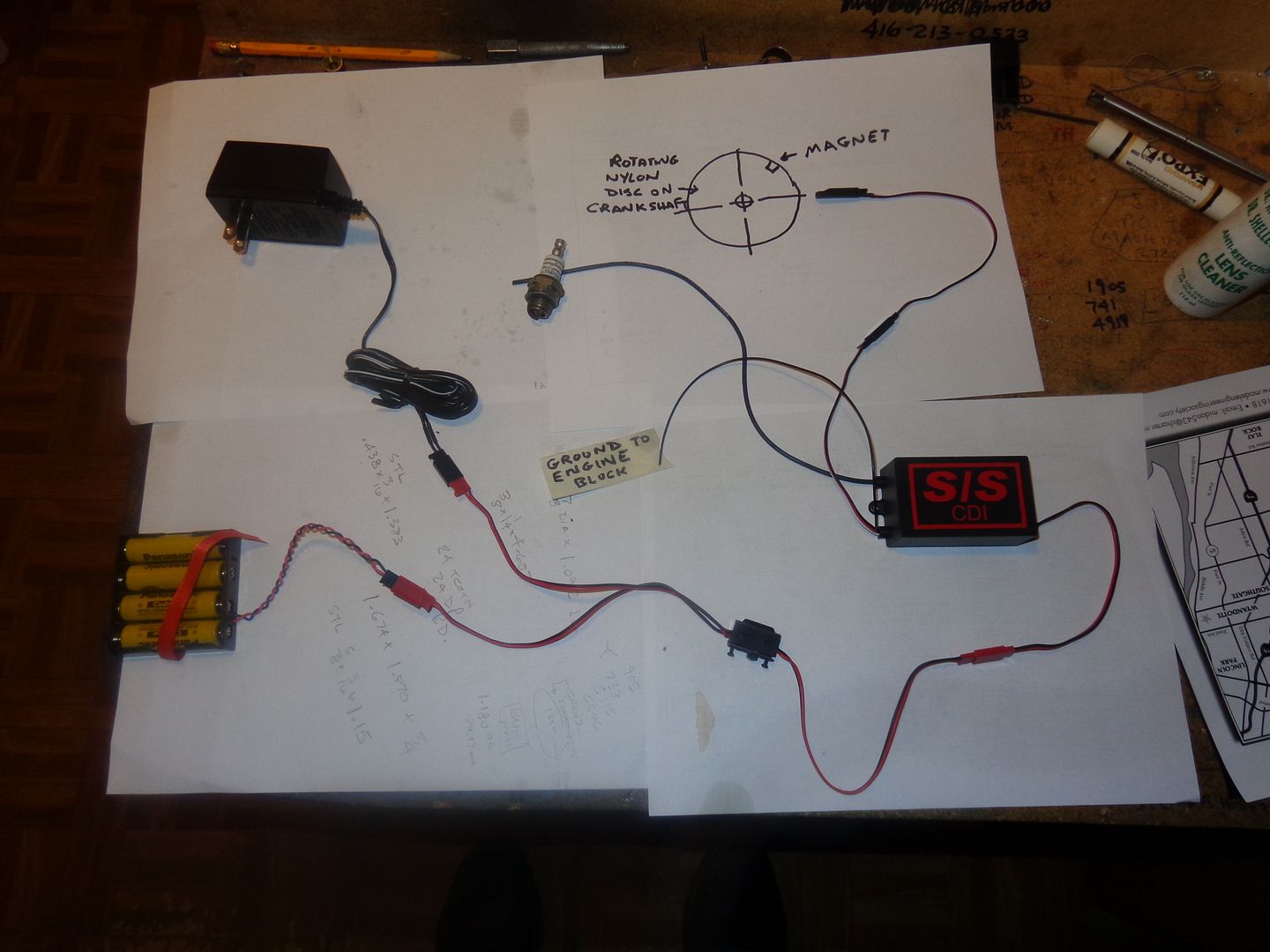
Today my CDI ignition arrived from S&S Engineering. What you see here is what $105 bought me. 4 rechargeable batteries, a case to hold them, a 110Volt adapter to charge them, an on/off switch with 3 sets of leads coming from it, a "black box" that contains the CDI, a Hall effect switch, and a very small magnet (which is not in the picture, but is represented in the picture beside the Hall effect sensor). I am not sure that I have everything sorted out properly, but will be sending this picture to Roy Sholl the owner of S&S for verification before I blow anything up or burn anything out. It seems pricey, but consider what I have been using--An automotive 12 volt coil--$50, a set of Chrysler ignition points at $16, a 12 volt condenser at $8, and a 12 volt battery which is not in any way portable at $100 minimum---which all adds up to about $175 and is not portable (easily at any rate). This whole electronic ignition thing is very new to me, and I will try to share what I know and find out with you. As I understand it, the magnet (which I mount in some type of non conductive nylon or plastic) rotates on the crankshaft, and every time it passes the Hall effect sensor (shown just below the picture of the magnet) it causes the Hall effect switch to trigger the CDI and output a spark to the sparkplug. I will probably try to be clever and mount the Hall effect switch on some kind of rotatable mount so that I can mess around with the timing while the engine is running.---Brian
 
Brain,

Glad you are taking this on :eek:.. another learning experience for both of us and others I'm sure. ;)
Will be following closely ...:):)

Pat H.
 
Pat---I am rather excited about this. I don't mean to imply by what I am doing that the Rupnow engine won't run satisfactorily with old style ignition points and coil. Its just that I have been wanting to try a CDI ignition for some time now, and this is an opportune time. I do know that the engine runs, as we all seen in the videos I posted, but I have my doubts about the coil and points I am using. If nothing else, this is hopefully going to settle the issue of ignition. If an engine runs, and there are no variables, then it should always start and run much the same, allowing for variations in temperature and fuel. I know beyond doubt that there are no mechanical variables. Having tried the smaller bore carb, and not seeing any real difference in "stability of performance", I will now have a go at the ignition.----Brian
 
I just received an email from Roy Sholl, verifying that my wiring set up is correct. Roy does pass along one caveat--DO NOT FIRE THE CDI WITHOUT THE COIL WIRE HOOKED UP TO A SPARKPLUG OR SPARK TESTER. It appears that doing so will fry the CDI and/or the Hall effect sensor.
 
The "suction" required to pull fuel out of that .040" diameter hole into the stream of air flowing thru the main body of the carb is created by the venturi effect in the carburetor. Venturi effect is basically a principle of air movement that says that any time air flowing thru a tube meets a restriction in the tube, a low pressure area will be created at or just behind the obstruction.

The actual mechanism is of no importance but I was pondering this the other day and came to the conclusion that the "suction" is probably just caused by the piston lowering the pressure in the manifold. The tube does create a restriction and this contributes to the pressure reduction.

I don't think it is a venturi effect.

Putting a finger over the intake increases the "suction" still further when we are pulling fuel up to start the engine.

Of course if I am wrong, I will be sure to be told in short order. Its one way to test a theory.

Jim
 

Latest posts

Back
Top