Potty Over Crank Wall Engine

Home Model Engine Machinist Forum

Help Support Home Model Engine Machinist Forum:

This site may earn a commission from merchant affiliate links, including eBay, Amazon, and others.
sbwhart said:
No more piddling about and stop trying to be cleaver just solder a lump of brass on the cover mill the top off square and drill the holes.

Stew

When all else fails, Get a Bigger Hammer. Like your solution, minimise the moving parts

Robert
 
;D You could have put the locating pins to good use there as well!


CYLINDER#3.JPG
 
tel said:
;D You could have put the locating pins to good use there as well!

I did on that last successful attempt

:bow:

Thanks for the tip ;D

Stew
 
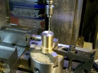
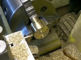
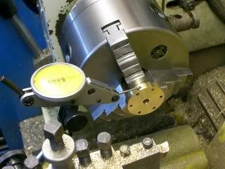
Things slowed down over the last couple of days but did manage to get a little done on the cylinder end covers, these are just plain turning jobs the hard bit is dealing with the thin section when you do the second op, I deal with it by puting my back stop in the head stock and pushing the thin cover up against it this help get it concentric and keep it secure. With the piston end covers with the stuffing gland its important to get the register with the cylinder concentric with the piston rod hole I do this by clocking the cover up in my three jaw i know that if I keep trying it in diferent positions one of them will be spot on.

Drilling the bolt holes and drilled to the full depth of the flutes this was enough to do three of the covers.

100_4642.jpg


A bit of fancy work

100_4651.jpg


Clocking the a cover up

100_4652.jpg


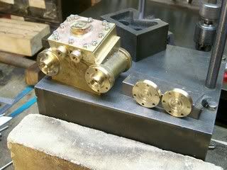
Covers done

100_4655.jpg


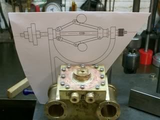
I'm planning on fitting a governor to the engine I drew one up but as I was unsure if I'd got the proportion correct

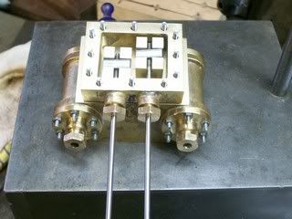
The first pic shows the governor against the cylinder at 1 : 1 scale

100_4650.jpg


Its far too big

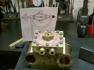
This is it 1/2 size

100_4649.jpg


Better but a wee bit small I think I somthing slighly bigger would be about right, some of the parts will be a bit on the small size but still doable.

Stew
 
I bet you're wondering where I've bin with this, well had a few days out over the weekend spent in windy Cornwall.

Got a bit done over the last couple of days made the nuts for the glands.

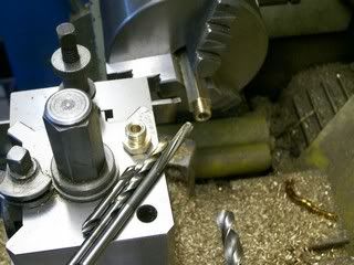
Not much to these except try and make them in one go to get the thread concentric with the bore and to ream the bore.

100_4661.jpg


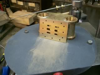
Also lapped the port face nice a flat using a bit of fine wet and dry on a flat surface, this is so the slide valve makes a nice seating onto it.

100_4677.jpg


I cut all the studs to length I'm just waiting for some stud lock to be delivered to fix them in place.

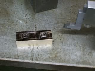
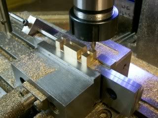
Made the slide valve, I made both valves in one piece saves setting up. Start by milling a bit of bar to size then as a guide mark out the recess.

100_4678.jpg


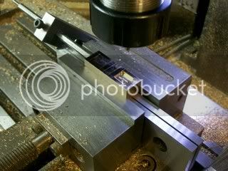
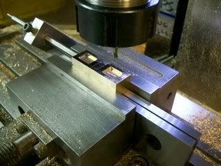
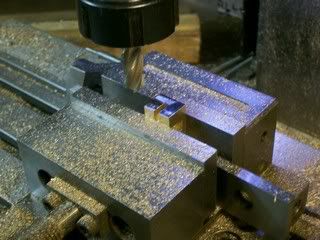
Then over onto the mill I like to work from the centre out but any way you're happy with will do its really quite easy if you've got a DRO I made slide valves without the DRO and you really have to be carful how you manage the back lash or you can get it all wrong. The first cut only has to be correct as you deepen the pocket you can finish the cut short it won't matter a jot it's only the edge that does the work. Just work clock wise around the pocket so you're not climb milling.

First done

100_4681.jpg


Second done

100_4683.jpg


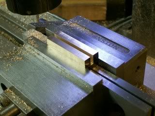
Flip it over and do the back

Slot for rod

100_4684.jpg


Check that depth is good

100_4685.jpg


Slot for cross bar.

100_4691.jpg


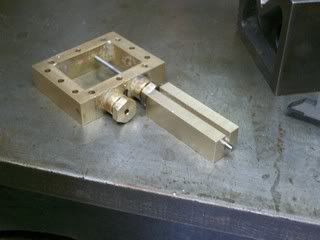
Then cut it in half to make the two, and mill to length and don't forget to lap the face nice and flat same as for the cylinder.

100_4692.jpg


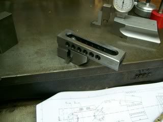
Next I tried out my new mini vice to make the cross bar this is made from a bit of 1/4" square mild steel again make the two together.

Put the bit of bar on a flat plate put the vice over the top of it tighten vice that the bar gripped nice and level,

100_4693.jpg


Then transfer the little vice to the big vice drill and tap.

100_4695.jpg


And thats the slide valve done and fitted.

100_4700.jpg


Stew
 
Here we go

[ame]http://www.youtube.com/watch?v=tkCtQiHsh3c[/ame]

Stew
 
Stew

That's brilliant! :bow:

Been following along since the beginning, and have enjoyed all of it.
I especially like the sound with the base acting as a "sounding box".


Cheers, Joe
 
Incredible! :bow:

Great work!!! love the sound that make at low speed!

Saludos
 
Stew,

Beautiful :bow: :bow:

It's bigger than I imagined and I too like the resonance from the mount, it gives an impression of controlled power.

Best Regards
Bob


Excellent!! Another runner and it sounds great. Good job of design and build.


Ron
 
Nice one Stew!!!

I thought I'd missed a bit of the build when it went from cylinders and valves to 'finished' so did a re-run over the thread, but apparently I didn't miss anything. Had you done the rest prior to starting the post?

Pete
 
doubletop said:
Nice one Stew!!!

I thought I'd missed a bit of the build when it went from cylinders and valves to 'finished' so did a re-run over the thread, but apparently I didn't miss anything. Had you done the rest prior to starting the post?

Pete

Peter I stopped posting the build on here as I got a bit disheartened with the interest and feed back it got, but I did carry the thread on her http://madmodder.net/index.php?topic=4201.msg52284#new

Thanks all you Chaps who have kindly commented.

So far its bin an interesting project, some of you Guys have commented on its size, it did come out bigger than I had in my minds eye, but in its original state it's not a very big engine, it would comfortably fit in a suite case, the model loco guys like to build narrow gauge Locos as they come out as large engines I thinks its something to do with scaling. The original engine has a fly wheel of about 24" dia I used a 7" fly wheel about 1/3 full size, and scaled everything from that, I think if I had used a 4" fly wheel some of the parts would have come out too small to comfortably make.

I don't intend running it on steam I don't think its performance on steam would be very good as I made the steam galleries on the small size.

I went away from the drawing I posted quite a bit:-as the build progressed I saw better or alternative ways of doing things, so at some point I will update them.

When I come to finish the engine off I want to round the sharp corners off and fill internal corners with something so that it looks more like a casting, can any of you guys suggest a filler.


Thanks again

Stew
 
Great job Stew!! A unique design well executed and certainly one to be proud of. Thanks for sharing the pictures and video.

Bill
 
Stew

I understand. I must admit I've slowed down my input to HMEM recently and only comment occasionally or reply if somebody posts to one of my threads.

On the filler; "Hemetal" (or some such) came to mind, it was a metal based filler we used in the RAF for bunging up things (can't think what). I believe it was in the Hematite gasket people product range. Had a dig around and Hematite is now Loctite and nothing about Hemetal

I did find this though that looks similar

http://www.eal.com.au/hypoxy.php?PHPSESSID=cc353e31e70189b5218aca111a6e97ec

Pete

Pete
 
Stew,
Here in the states we have something called JB Weld, also a 2 part epoxy similar to what Pete showed. Its good stuff and supposedly good up to 500 degrees F. If you go the epoxy route, keep in mind that the longer curing formulas can and will slump some as they set up. For that reason I might suggest you look for one of the faster curing formulas, one that will give you enough working time to make your fillets, but which will set ujp quick enough to avoid the slumping.

Bill
 
Hi Stew,
A most admirable piece of work. My first love is steam engines and especially ones with all kinds of mechanical links and levers. As has been stated it runs great and has that wonderful sound at low speed.
gbritnell
 
Thanks for you comments and pointers for fillers Guys


doubletop said:
I understand. I must admit I've slowed down my input to HMEM recently and only comment occasionally or reply if somebody posts to one of my threads.

Pete

I must confess thats what I tend to do also:- I'm guilty of not being the most chatty person in the world I tend to just say whats needed and then move on:- but that way you soon run out of places to move to.

Stew
 
Well, time to pic this back up again by making a start on the governor in fact I've been agonizing over it for a couple of weeks for some reason I've been full of self doubt and uncertainty, I've drawn and redrawn the governor up 1/2 a dozen times changing my mind as to type and size, eventually I gave myself a good talking too:-just get on with it and stop p******g around.

So her we are first bit the little spinning things that hold the arms, making small parts can be a bit of a pain if you don't get the machine sequence right, you can end up with nothing to hold onto.

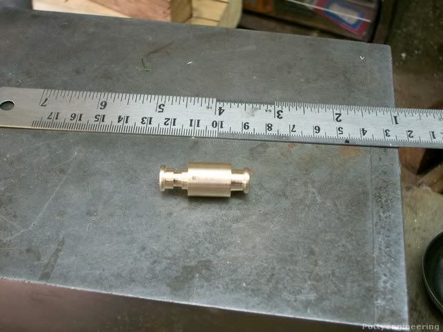
So started off on the lathe and machined out the outer shape and reamed the bore out 3mm, I'm making the two out of the same bit of bar one at each end.

Her they are one at each end

131_0155.jpg


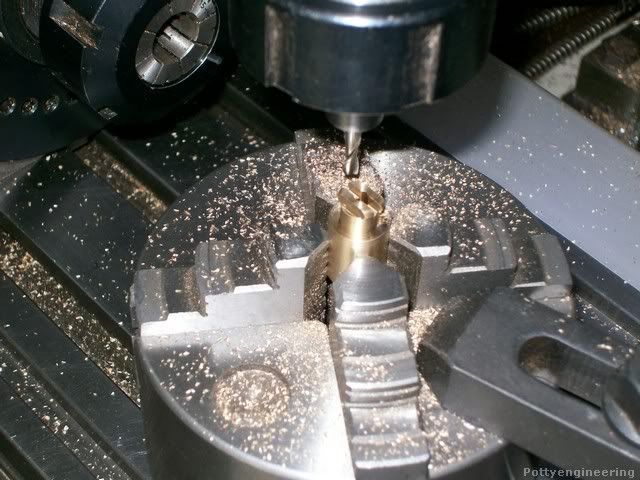
Then over onto the mill gripped in the four jaw self centering chuck, centre the chuck on the centre line of the quill, zero the dials, then with a 2mm slot drill, mill the slot across the end, then with a bigger end mill, mill flats either side, flip it round and repeat on the other end.

131_0157.jpg


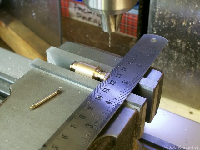
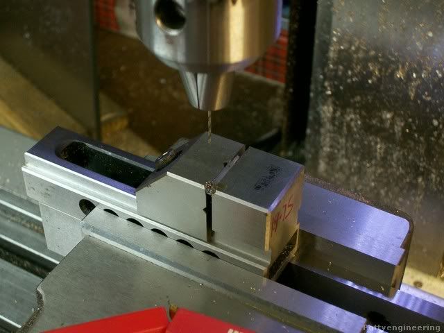
Then over to the vice first set the quill on to the centre of the bar, with a ruler or straight edge in the slot grip it level in the vice, index to position and drill through 0.8mm for the pivot pin.

131_0158.jpg


Back onto the lathe and part them off, doing them this way you had the bar to grip onto.

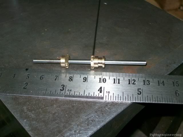
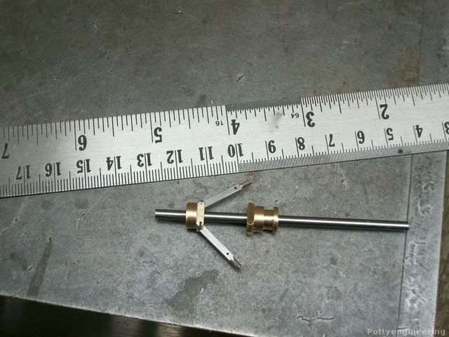
Her they are on a length of 3mm stainless that will be the spindle with a bit of 0.8 piano wire through pivot hole.

131_0167.jpg


Any way on with the link arms first the arms that will hold the balls.

Turn and thread a small length of 4 mm dia bar M2 I took care to get the length the same on both bars I don't want the balls hanging odd

131_0184.jpg


Then carefully mill the 4mm dia into 2mm square.

Then drill 0.8mm for the links.

131_0185.jpg


Her they are fitted.

131_0186.jpg


That was the easy bit now for the more complex yolk link.

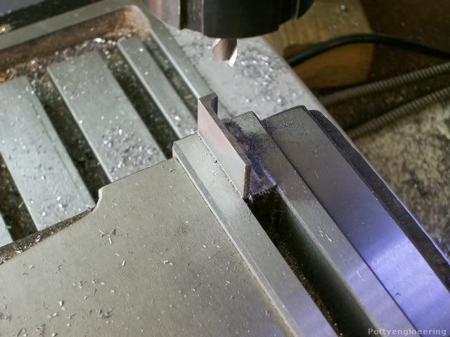
First mill up the shape in a chunk of mild steel more than enough to make two links.

131_0188.jpg


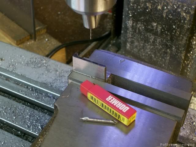
Zero the mill on the x, Y edges of the bar, and drill 0.8mm holes in correct position as deep as the slender drill would go, fast speed, drop of cutting fluid and peck the drill in and out to clear the swarf.

131_0198.jpg


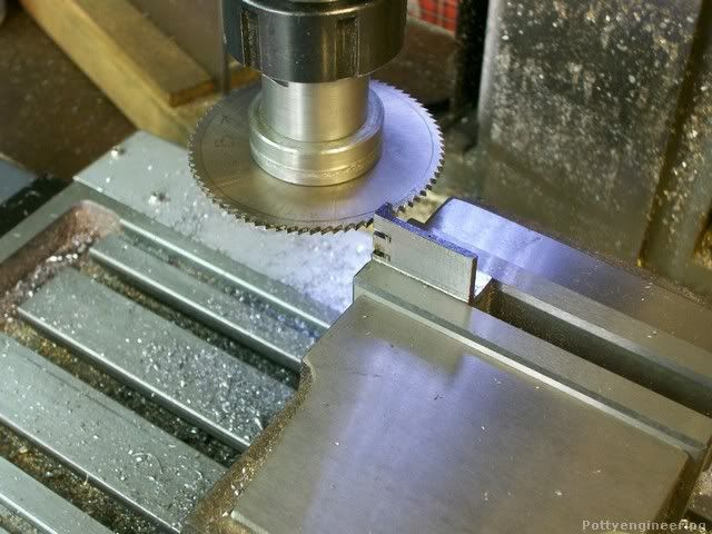
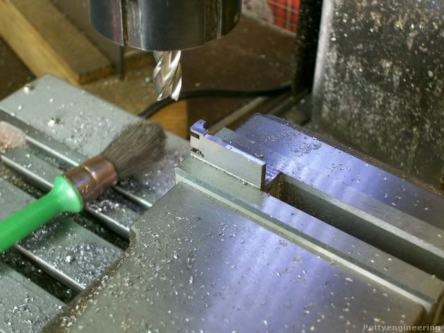
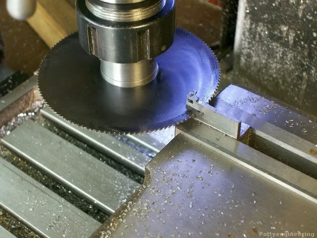
Now for milling the slot, the arms will only be 1mm thick and as the slitting saw will tend to spring the arms open the slots were cit in the bar well away from the edge to give a thicker section I'll mill them to size later.

131_0199.jpg


With thin sections its important to use good sharp tools if they are blunt the part will be bent, so with a new end mill skim off arms until 1mm thick, then mill step, to form the yolk.

131_0202.jpg


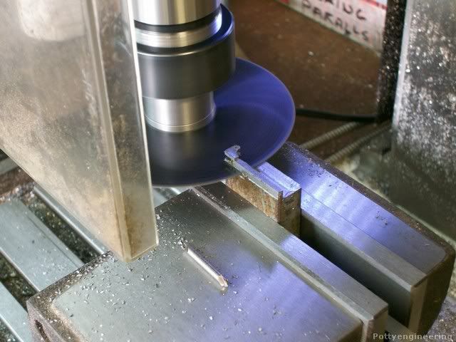
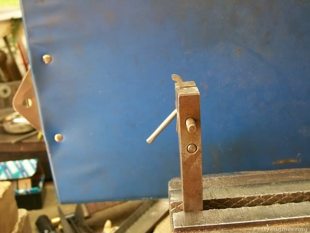
With another bigger dia slitting saw cut the link from the bar leaving plenty of meat around the arms for finishing later.

131_0204.jpg


The second arm was just a repeat of the first, this is it being split off, I was a little lean on material, but their was just enough.

131_0205.jpg


The links were flipped over and the other side end milled to size sorry no pics.

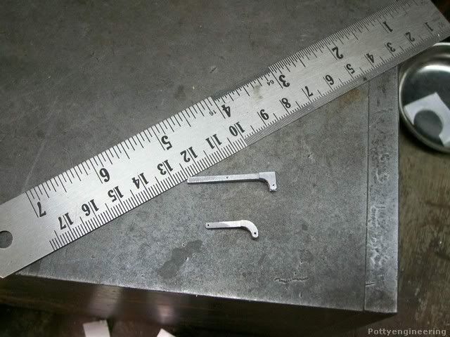
The hook was filed to shape.

131_0208.jpg


I left them over long to give something to grip on only cutting them of to length as a last op.

Here's one finished with its mate.

131_0210.jpg


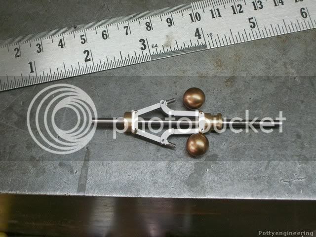
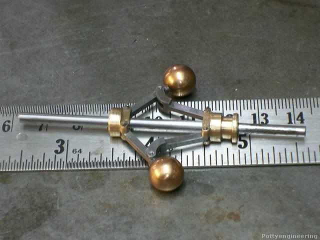
And the finished bits assembled, they still need a bit of a clean up but not looking too bad. It will be fitted with some 3/8" phosphor bronze balls, when I work out a way to drill and tap them.

131_0211.jpg


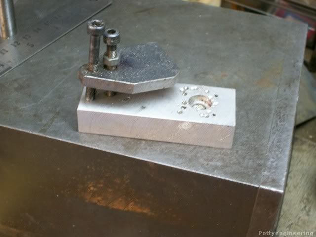
Had a rummage through my bits and pieces box and came up with this I've used this for all sorts of odd fixtures, and it will be just the ticket for the ball job.

131_0213.jpg


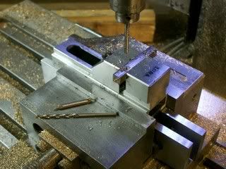
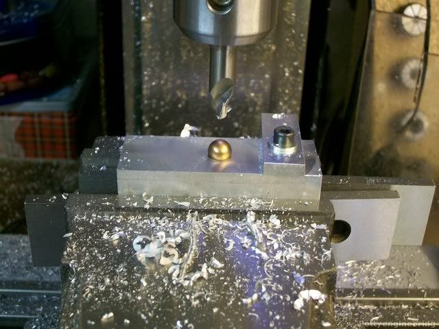
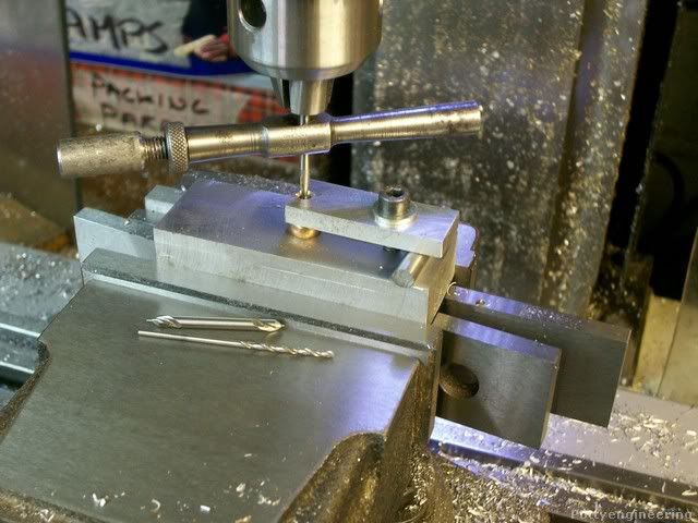
So gripped it in the vice and fly cut the face up nice and flat, then drilled a bit of ally bar for a top clamp, fixed it to the base, locked the x and y axis of the mill. And drilled a 3 mm hole in the clamp into the base.

131_0215.jpg


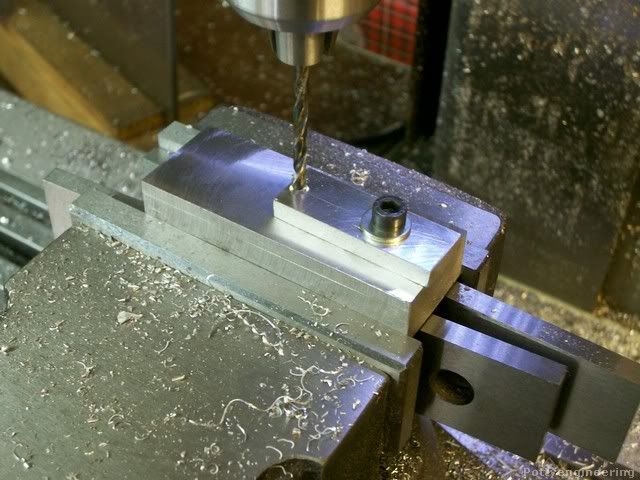
Then with a big centre drill drilled a big cone into the base for the ball to sit in.

131_0217.jpg


Clamp the ball in the fixture centre drill followed by an M2 tapping drill and tap, I used the chuck to guide the tap to keep it square.

131_0219.jpg


Cleaned things up and fixed the pins and balls with a tiny bit of supper glue.

Looking good

131_0225.jpg


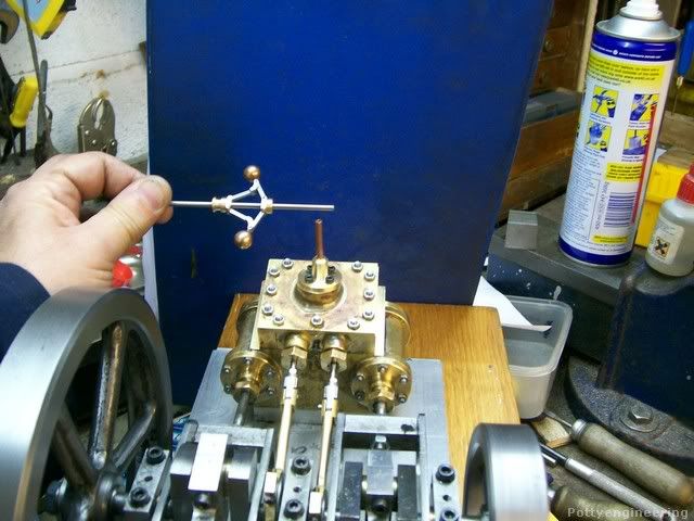
Scale looks about right :thumbup:

131_0227.jpg


Pleased how that turned out.

:D


I was kind of working from drawings and from gut feel for the job, I'll bring the drawings into line with what I ended up with and post them her along with the other governor designs I came up with some of you guys may be able to put them to use.

Stew
 

Latest posts

Back
Top