Lesmo
Well-Known Member
- Joined
- Mar 1, 2011
- Messages
- 142
- Reaction score
- 16
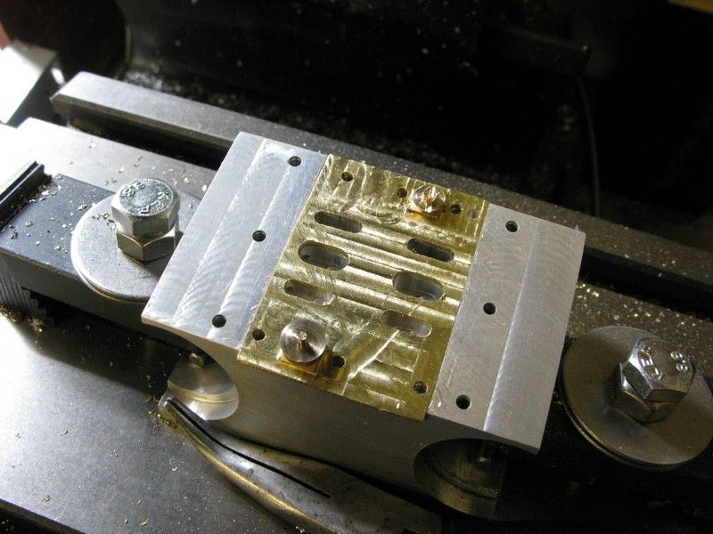
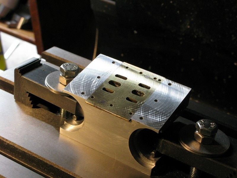
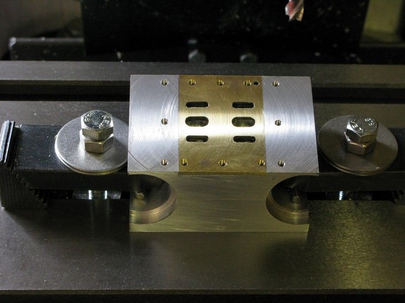
Well I finished most of the 3d drawings and now have a better understanding of what makes this overcrank engine tick, so I made a start on the main bit, the engine block assembly.
I was uncertain whether to post this build so soon after Stew's own excellent build, but thought that it may appeal to anyone like myself who is short on experience and unsure whether to tackle something like this, having only one engine under his belt, or have been put off by having to silver solder such big lumps of brass together. Here goes.
During the drawing phase I decided to depart from Stews design and make the block from aluminium but keep the brass cylinders. My reasoning being, with brass costing an arm and a leg, one machining screwup could be expensive, more so,if I screwed up twice. So I bought a chunk of 75x75mm ally enough for several attempts if necessary, for the same money as one lump of brass.
I was a little uncertain given the nature of ally whether it would bond with the brass cylinders so I did an experiment using araldite two part epoxy, I bonded a half circle of scrap ally to a 16mm brass dowel and left it overnight to cure. The next day I put the ally in the vice and was surprised at how little force was required to break the joint. I suppose there must be ally etching adhesives out there as Lotus use epoxy for bonding ally on their sports cars, but I could not find anything on the net, so it was back to the drawing board to re-design the block so that I would not have to rely on bonding alone but use a clamping action to hold the cylinders in place.
I made the block a little wider than the half circle shown on the plans, then it was out to the shop to make a start. First I carved a chunk of 75x75 ally and faced the ends square
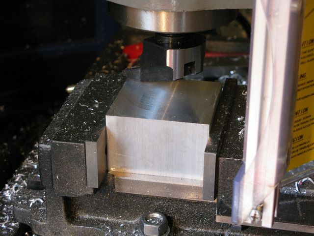
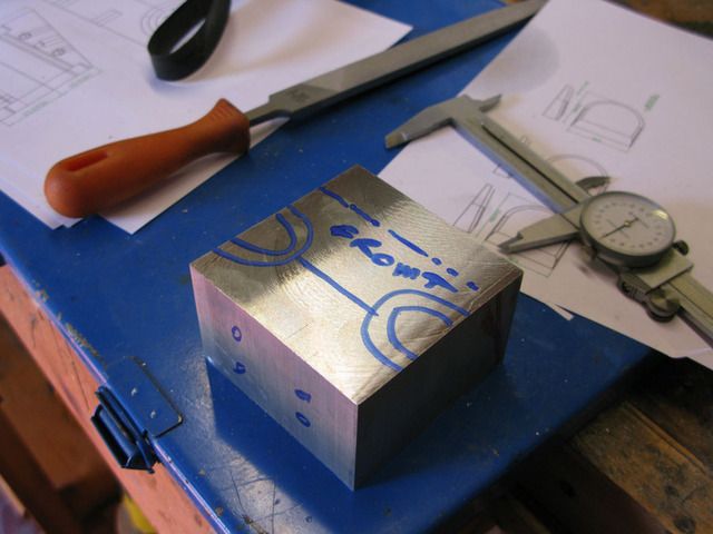
Marked up the orientation of the clamp bolts and cylinders
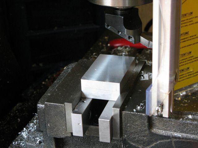
then split it across the cylinder centerline with my band-saw and faced both halves
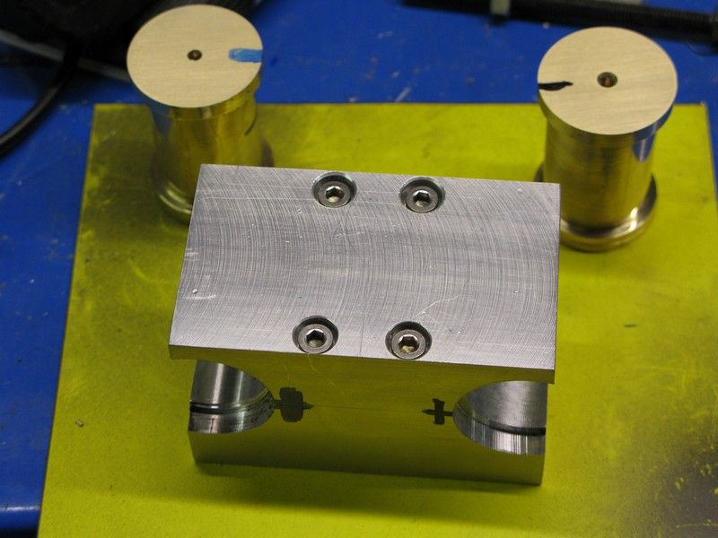
which were were then drilled and tapped for 4mm cap heads.
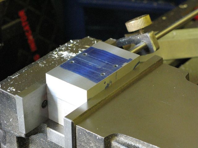
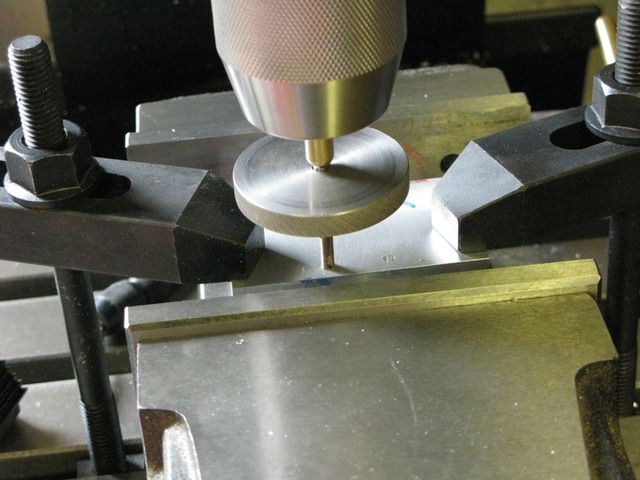
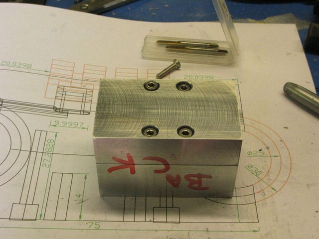
After assembly it was all faced up square and the centers marked for the cyl positions.
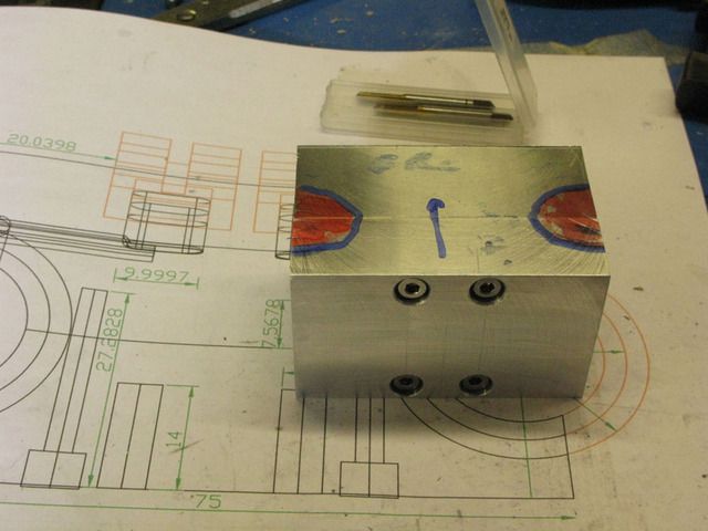
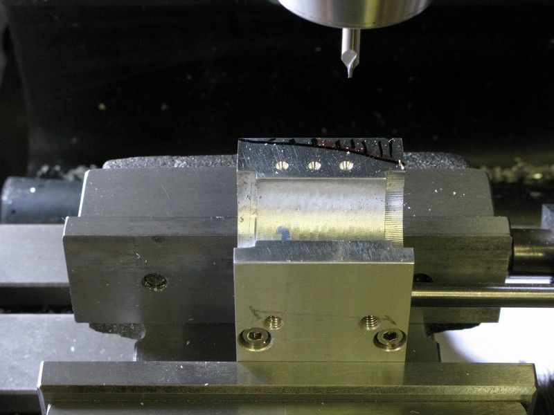
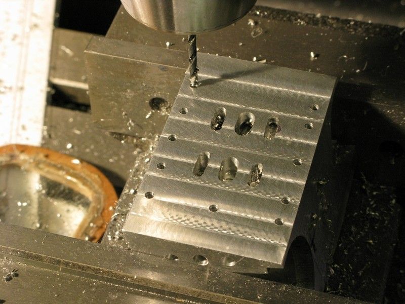
They were center drilled
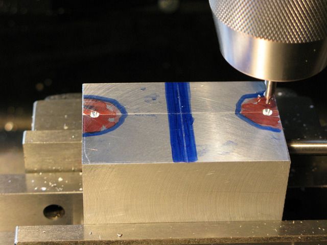
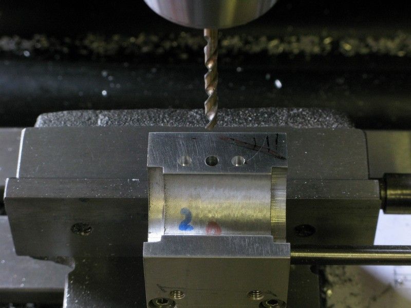
Then drilled through with an 8mm drill followed by 12mm 16mm and 20mm endmills
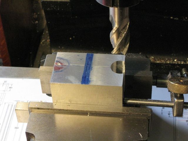
and finally bored out to 20mm using a gauge plug to ensure the correct final size
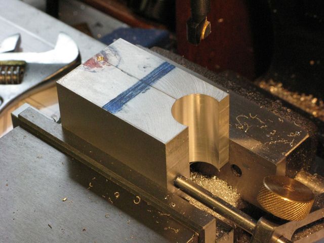
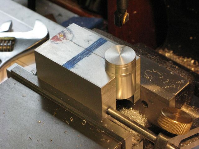
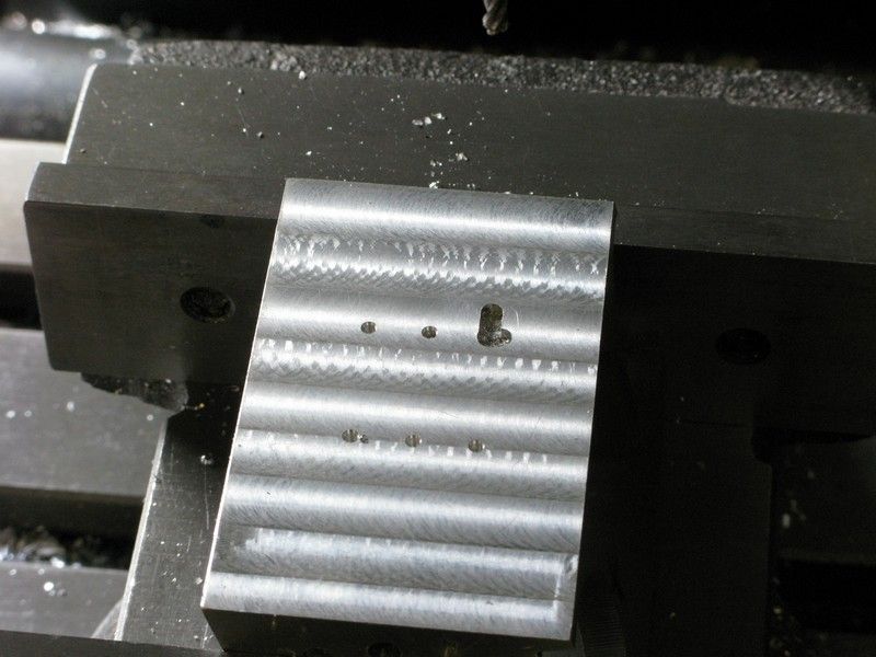
Without moving the piece, the 5mm counter bore was carried out, using a dial indicator for cutter adjustment and a hole gauge and micrometer as a double check.
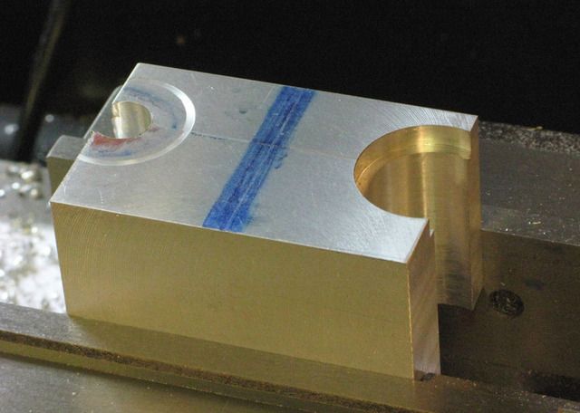
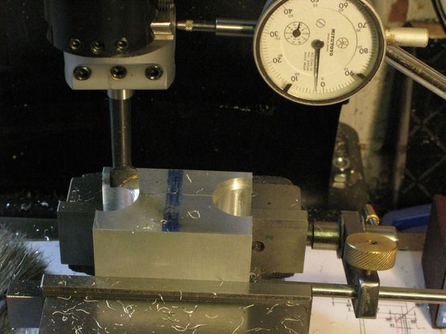
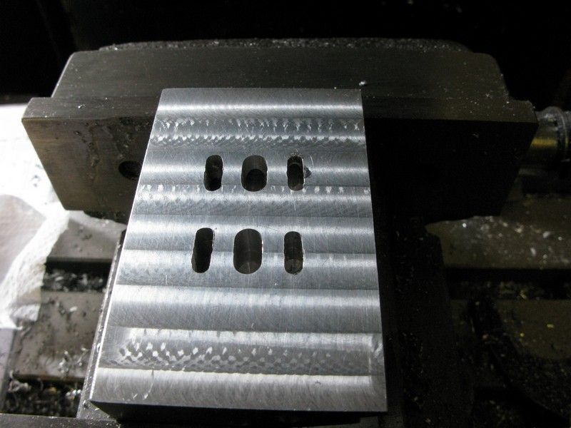
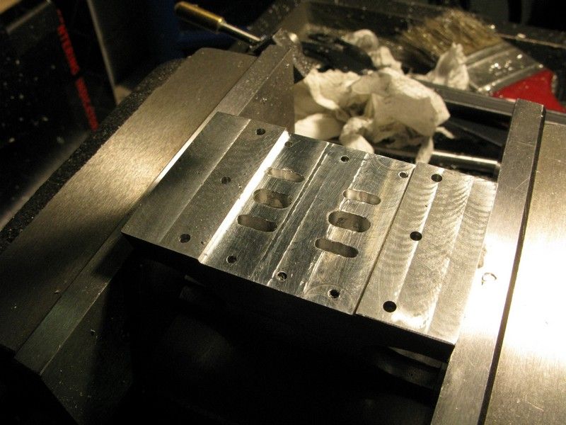
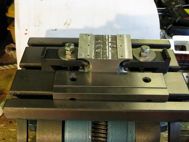
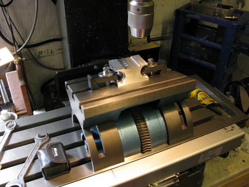
The piece was then moved to the other cylinder position and the same operation repeated until I had this.
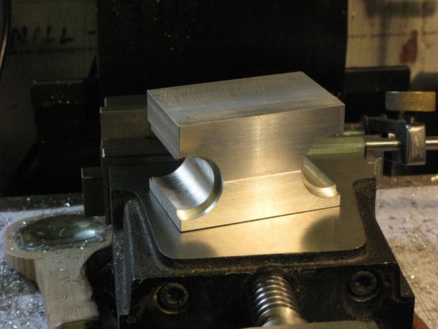
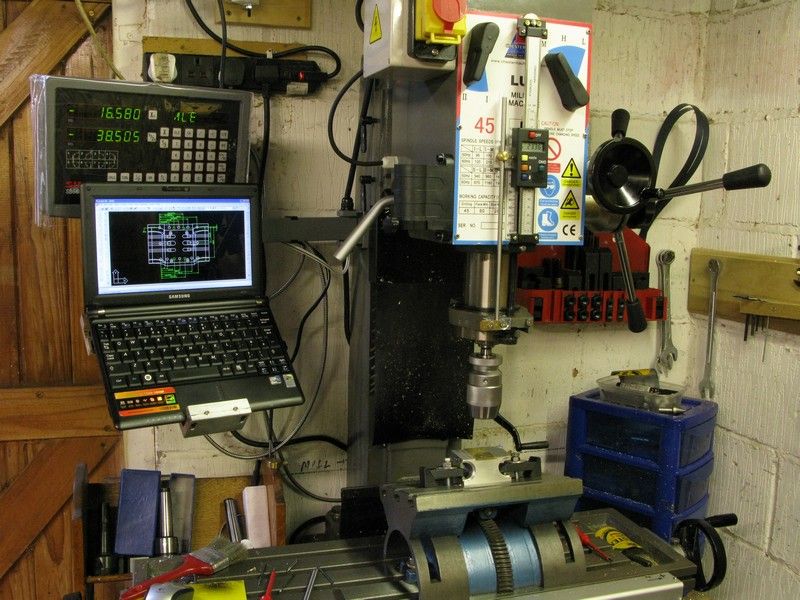
So far so good. Next up were the brass cylinders which were a fairly straightforward turning job, creeping up very gently on size and making good use of the dial indicators on both X & Y feeds and using the split ally block as a further check.
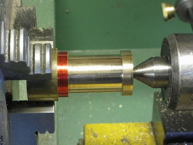
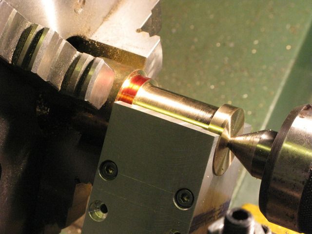
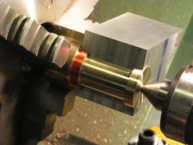
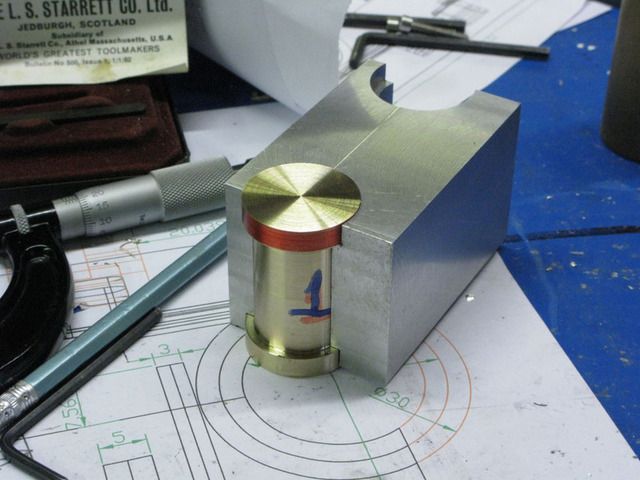
With the material leftover from the cylinders I made 2 backplates for the cylinders and put them to one side for a little decorative work later.
Next I turned the cylinder heads.
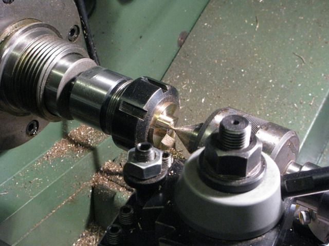
The heads call for a ME 5/16 32 tpi 6mm deep threaded blind hole and I only have metric taps & dies, and 60 deg thread cutters, also my 8mm shank internal cutter will only thread a 10/11mm hole, so the hunt was on for a cutter that could cut a thread in a 7mm ish hole.
After searching the net I eventually found what I was looking for here http://madmodder.net/index.php?topic=3523.0 so taking a length of 8mm silversteel/drill rod I was able to produce a cutter that would cut inside a 7mm hole and hardened it.
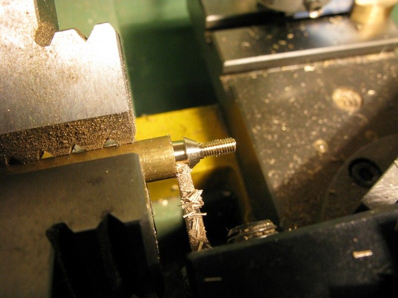
First set up the lathe to cut 32 tpi, fitted one of the cyl heads into a collett chuck and bored the hole part way through the head to accommodate the gland nut, the hole is as mentioned, 7mm diameter and 6mm deep. the the cyl head being 10mm deep. I wanted a full depth thread but had to find a way of stopping the tool crashing at the end of travel and wrecking the part and the tool. You will gather that I am still a newbie.
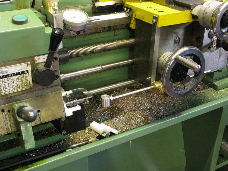
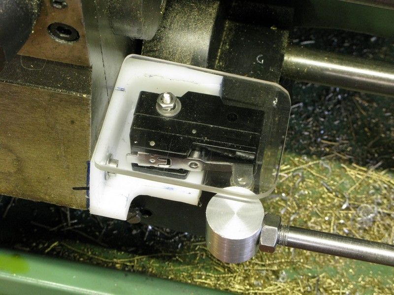
I wound in the tool until it bottomed out and set the dial indicator that sits in my adjustable table stop to a reading of plus 0.35 mm. This is just over the distance the table travels whilst cutting, from the time the Di needle moves off zero, to my releasing the clasp nut. It is my reaction time plus a bit. As you can guess I had practised this with a few dry runs to see what my worst time was, and when I had a consistent time, I went for it. Success, the male thread fitted spot on with no sign of play.
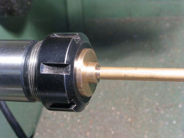
I had cut my first blind full depth thread without wrecking the piece or the tool. There are probably far better and less nerve racking ways to do this I am sure, but it was a case of needs must, and I must admit, I do like threading on the lathe so it was quite satisfying.
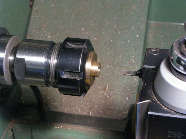
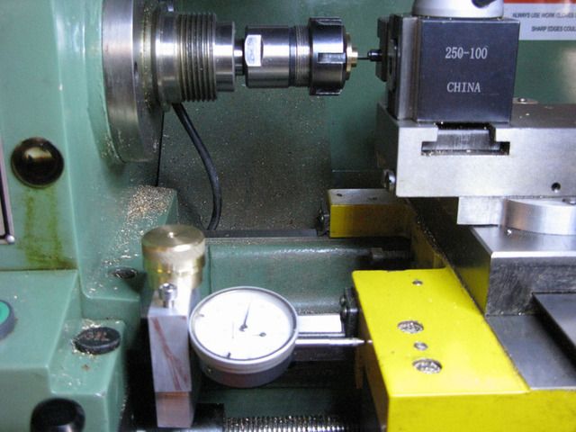
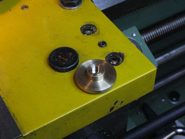
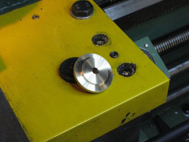
I certainly look forward to any helpful comments as to how it should be done.
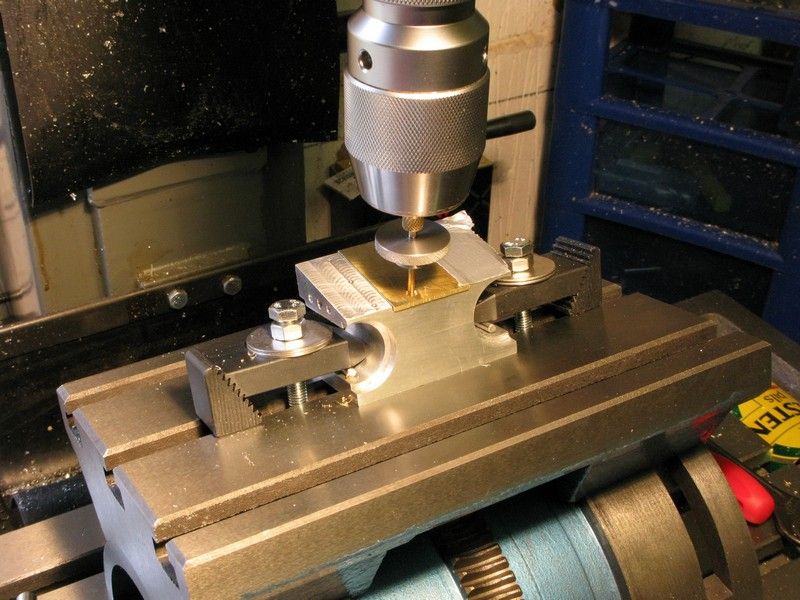
Back at the engine block I dry assembled the cylinders and nipped up the clamp bolts then lightly faced the block and cyl's both back and front.
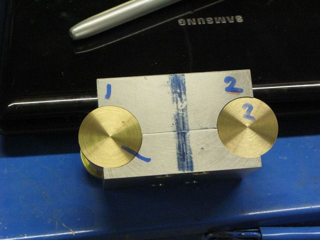
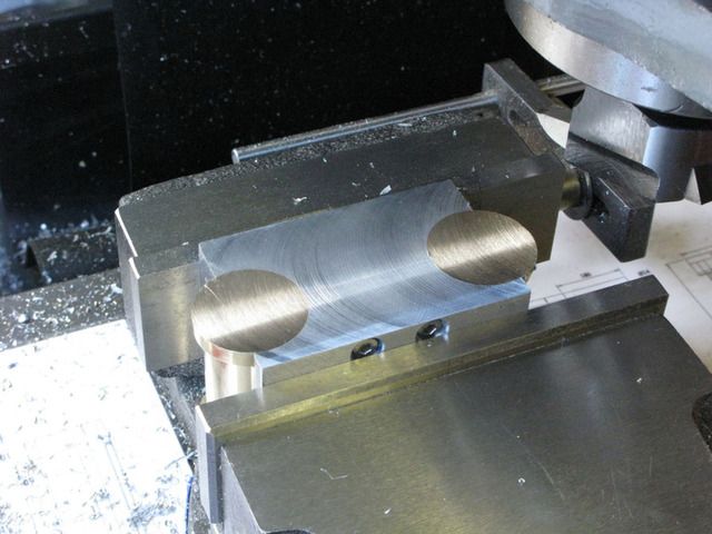
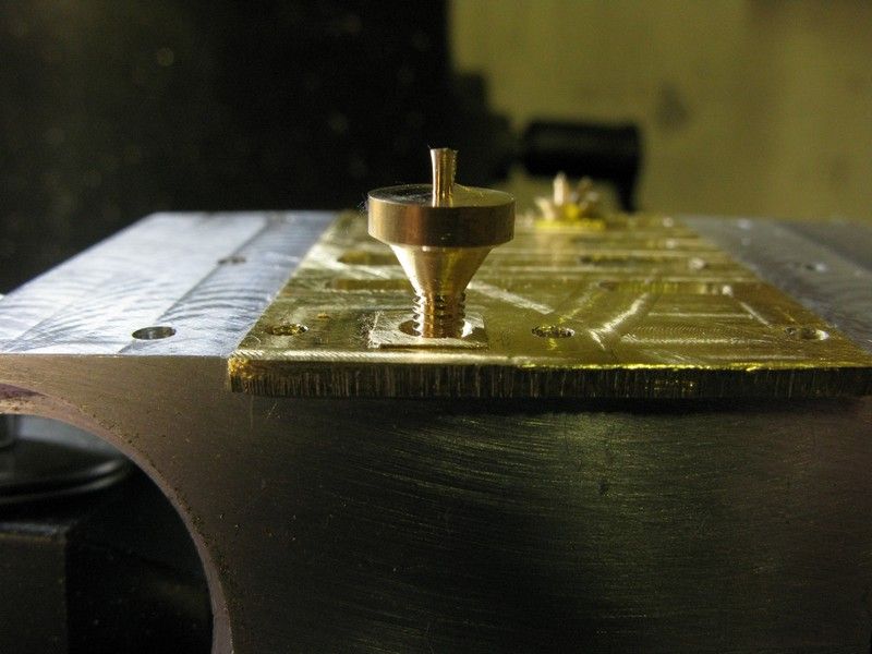
I put the block aside to do the decorative work on the cyl back plates. I had the previous evening been playing with the 3d cad to see what the cutting patterns would be like for a given radius of cutter, depth of cut and the offset from the disc center. They were all based on an 8 point star. I had previously seen a small star on one of Stew's other builds, I think it was the popcorn engine, but wanted something larger.
I set up the rotab with 3 jaw chuck fitted and a collett chuck in the three jaw chuck chuck, you get the idea. The cutter set at 35mm rad & 2mm off centre and the cut 1mm deep.
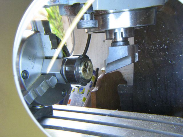
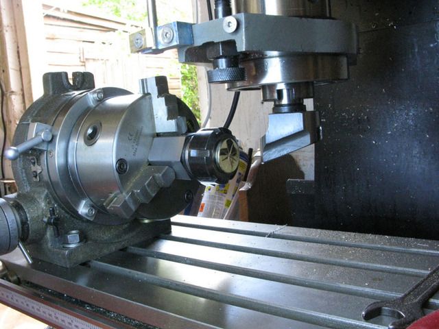
Worked like a dream and came out exactly as the cad model predicted.
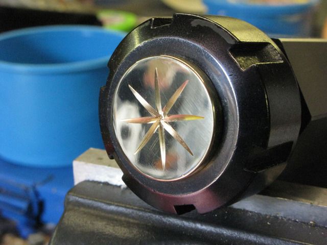

Playtime over, that's me up to date with the story so far.
I was uncertain whether to post this build so soon after Stew's own excellent build, but thought that it may appeal to anyone like myself who is short on experience and unsure whether to tackle something like this, having only one engine under his belt, or have been put off by having to silver solder such big lumps of brass together. Here goes.
During the drawing phase I decided to depart from Stews design and make the block from aluminium but keep the brass cylinders. My reasoning being, with brass costing an arm and a leg, one machining screwup could be expensive, more so,if I screwed up twice. So I bought a chunk of 75x75mm ally enough for several attempts if necessary, for the same money as one lump of brass.
I was a little uncertain given the nature of ally whether it would bond with the brass cylinders so I did an experiment using araldite two part epoxy, I bonded a half circle of scrap ally to a 16mm brass dowel and left it overnight to cure. The next day I put the ally in the vice and was surprised at how little force was required to break the joint. I suppose there must be ally etching adhesives out there as Lotus use epoxy for bonding ally on their sports cars, but I could not find anything on the net, so it was back to the drawing board to re-design the block so that I would not have to rely on bonding alone but use a clamping action to hold the cylinders in place.
I made the block a little wider than the half circle shown on the plans, then it was out to the shop to make a start. First I carved a chunk of 75x75 ally and faced the ends square

Marked up the orientation of the clamp bolts and cylinders

then split it across the cylinder centerline with my band-saw and faced both halves

which were were then drilled and tapped for 4mm cap heads.


After assembly it was all faced up square and the centers marked for the cyl positions.

They were center drilled

Then drilled through with an 8mm drill followed by 12mm 16mm and 20mm endmills

and finally bored out to 20mm using a gauge plug to ensure the correct final size


Without moving the piece, the 5mm counter bore was carried out, using a dial indicator for cutter adjustment and a hole gauge and micrometer as a double check.


The piece was then moved to the other cylinder position and the same operation repeated until I had this.

So far so good. Next up were the brass cylinders which were a fairly straightforward turning job, creeping up very gently on size and making good use of the dial indicators on both X & Y feeds and using the split ally block as a further check.


With the material leftover from the cylinders I made 2 backplates for the cylinders and put them to one side for a little decorative work later.
Next I turned the cylinder heads.

The heads call for a ME 5/16 32 tpi 6mm deep threaded blind hole and I only have metric taps & dies, and 60 deg thread cutters, also my 8mm shank internal cutter will only thread a 10/11mm hole, so the hunt was on for a cutter that could cut a thread in a 7mm ish hole.
After searching the net I eventually found what I was looking for here http://madmodder.net/index.php?topic=3523.0 so taking a length of 8mm silversteel/drill rod I was able to produce a cutter that would cut inside a 7mm hole and hardened it.
First set up the lathe to cut 32 tpi, fitted one of the cyl heads into a collett chuck and bored the hole part way through the head to accommodate the gland nut, the hole is as mentioned, 7mm diameter and 6mm deep. the the cyl head being 10mm deep. I wanted a full depth thread but had to find a way of stopping the tool crashing at the end of travel and wrecking the part and the tool. You will gather that I am still a newbie.
I wound in the tool until it bottomed out and set the dial indicator that sits in my adjustable table stop to a reading of plus 0.35 mm. This is just over the distance the table travels whilst cutting, from the time the Di needle moves off zero, to my releasing the clasp nut. It is my reaction time plus a bit. As you can guess I had practised this with a few dry runs to see what my worst time was, and when I had a consistent time, I went for it. Success, the male thread fitted spot on with no sign of play.

I had cut my first blind full depth thread without wrecking the piece or the tool. There are probably far better and less nerve racking ways to do this I am sure, but it was a case of needs must, and I must admit, I do like threading on the lathe so it was quite satisfying.


I certainly look forward to any helpful comments as to how it should be done.
Back at the engine block I dry assembled the cylinders and nipped up the clamp bolts then lightly faced the block and cyl's both back and front.


I put the block aside to do the decorative work on the cyl back plates. I had the previous evening been playing with the 3d cad to see what the cutting patterns would be like for a given radius of cutter, depth of cut and the offset from the disc center. They were all based on an 8 point star. I had previously seen a small star on one of Stew's other builds, I think it was the popcorn engine, but wanted something larger.
I set up the rotab with 3 jaw chuck fitted and a collett chuck in the three jaw chuck chuck, you get the idea. The cutter set at 35mm rad & 2mm off centre and the cut 1mm deep.


Worked like a dream and came out exactly as the cad model predicted.


Playtime over, that's me up to date with the story so far.


![DreamPlan Home Design and Landscaping Software Free for Windows [PC Download]](https://m.media-amazon.com/images/I/51kvZH2dVLL._SL500_.jpg)


![MeshMagic 3D Free 3D Modeling Software [Download]](https://m.media-amazon.com/images/I/B1U+p8ewjGS._SL500_.png)


