Horizontal IC Engine 5/8" Bore

Home Model Engine Machinist Forum

Help Support Home Model Engine Machinist Forum:

This site may earn a commission from merchant affiliate links, including eBay, Amazon, and others.
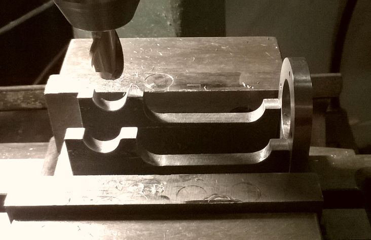
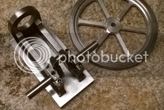
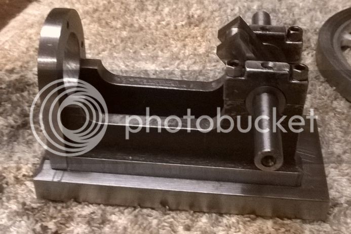
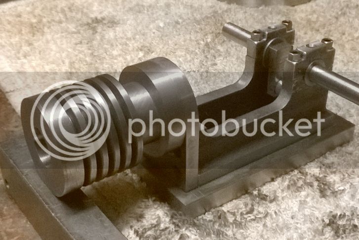
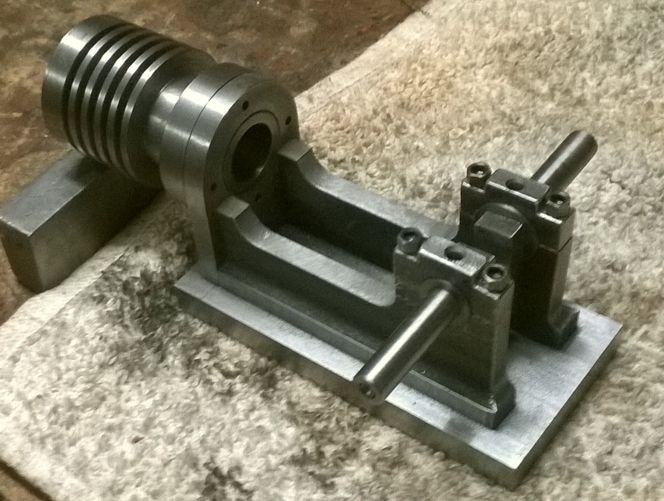
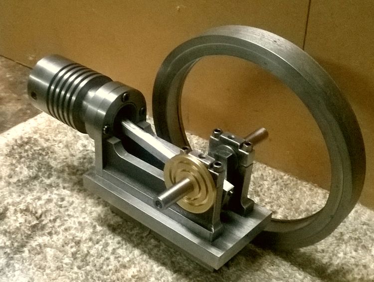
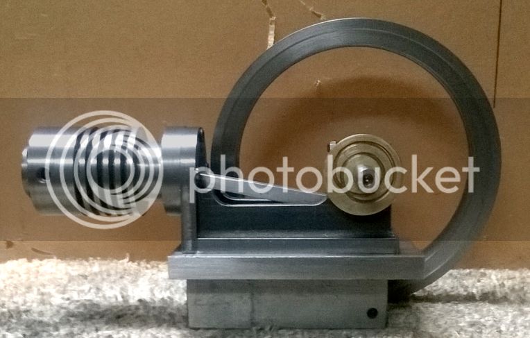
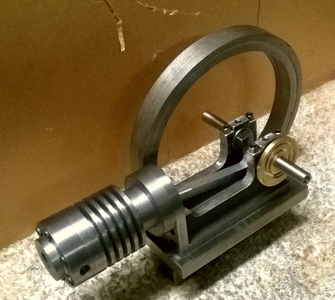
Got some more stuff done today. I got the crankshaft, bearings and caps all installed. I started off using a 1/2" ball nose end mill to cut the frame to receive the crankshaft main bearings.

WP_20141016_007_zpsf0799ef5.jpg


WP_20141016_008_zps1917e34b.jpg


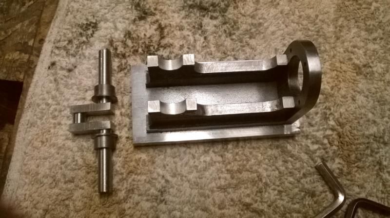
The main bearings were turned from cast iron...

WP_20141016_009_zps350db572.jpg


WP_20141016_010_zps09890037.jpg


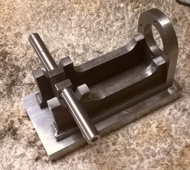
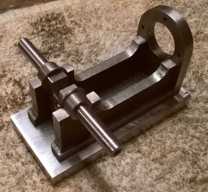
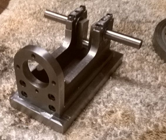
And, finally, I finished the main caps, drilled and tapped the holes for the screws and put it all together.

WP_20141017_001_zpsd329519a.jpg


WP_20141017_002_zpsc715eee2.jpg


WP_20141017_003_zps3948b41c.jpg


Next, I'll get started on the cylinder.

Chuck
 
Another engine to build on my build list. Looks like I have to stop fishing for a while.
Will follow your post closely. Just came from a very good deep sea fishing trip in wild Sarawak.
Fishing biting like crazy. Good eating fish---------Red Snappers.
The native head hunters missed Gus!!!.Gus survived. Oops.That was 100 years ago.
 
Thanks, Gus, this one has plans in the making so there's no excuse not to give it a try!

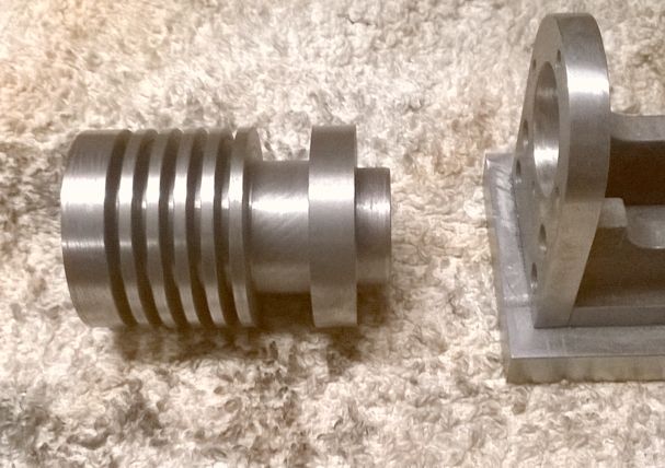
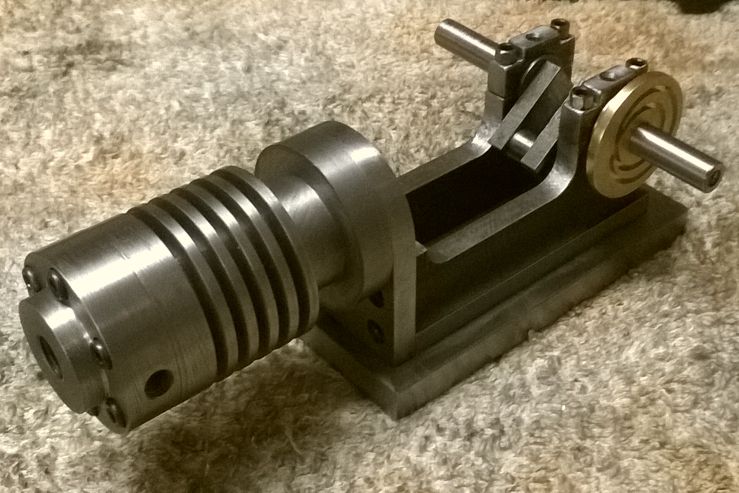
So, instead of sitting in my recliner in front of the laptop all night, I spent some more quality time in my shop making the cylinder.

WP_20141017_004_zps8a04d655.jpg


WP_20141017_005_zps142d838b.jpg


WP_20141017_006_zps8bba27bf.jpg


It looks a little chunkier than I had thought it would, but it'll do for now. The bore is only 0.625" but I left enough meat around it that I can bore it out to 0.750" if I need to. So, perhaps tomorrow I'll get on to the head.

Chuck
 
The way you hold the pieces outside the vice, post#18, clever as usual...
Thanks!

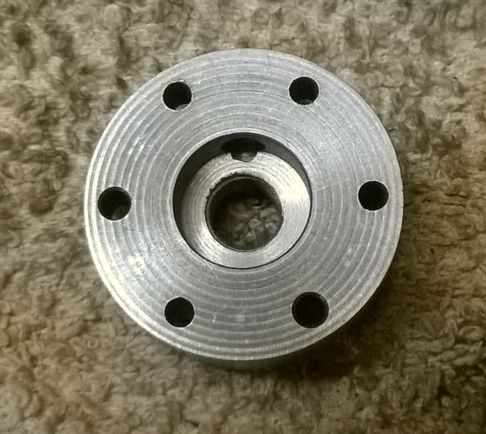
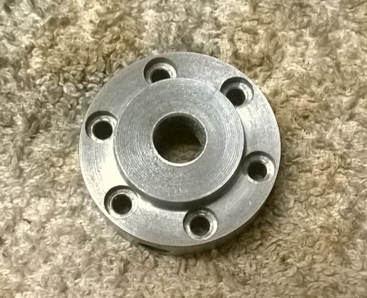
Today I made the cylinder head. I started with a piece of cast iron, turned it down to 1.5" and shouldered down the outboard end to 15/16". Then I reversed it in the chuck and drilled it through the center with a 9mm bit. I cut a 5/8" diameter, 1/4" deep recess in the bottom side for the combustion chamber. I mounted the piece on my rotary table and drilled and counter bored the 6 holes for the head bolts. I drilled and tapped a 1/4" model pipe taper in the side for the intake and exhaust. Finally, I tapped the spark plug hole 10mm x 1mm. Here's the finished product.

WP_20141018_001_zps067354df.jpg


WP_20141018_002_zps1fcbd518.jpg


WP_20141018_003_zps5aceb2f5.jpg


Next I got started on the piston. It's 5/8" diameter and 1" long.

WP_20141018_004_zps6f605dfb.jpg


However, I need to finalize the design of the connecting rod before I finish the piston.

Chuck
 
A few more pictures with the beginnings of a flywheel...

WP_20141020_003_zpsb84b0042.jpg


WP_20141020_001_zps8cba4920.jpg


WP_20141020_002_zps41ac3b74.jpg


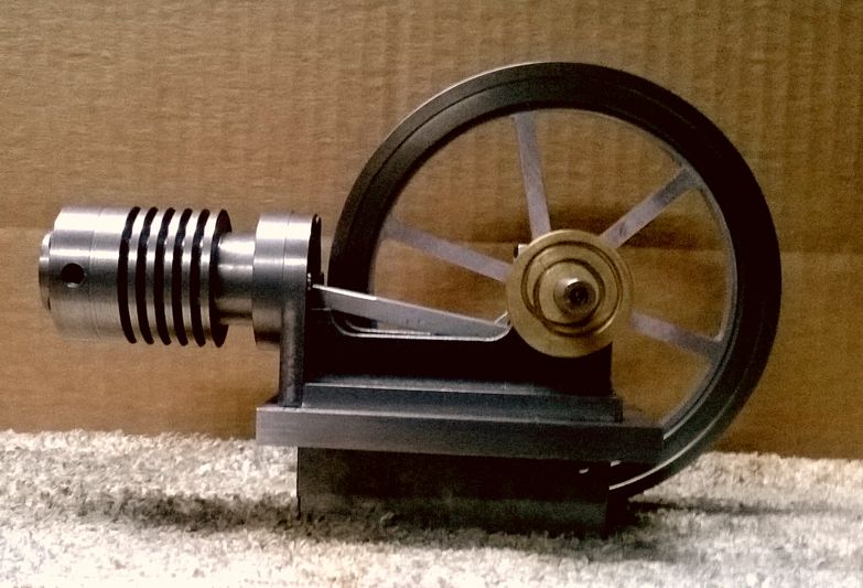
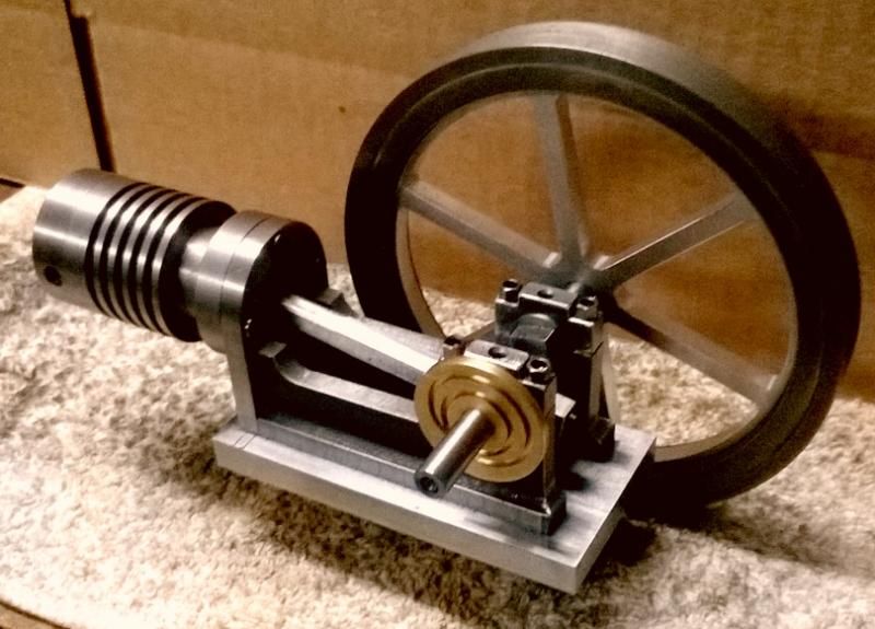
The flywheel rim in the picture is the remnant of a cast iron flywheel from a previous life which had some broken spokes. It's about 5.25" diameter which is quite large for this size engine, but it's just what I wanted. I'll mill a spoked flywheel center from aluminum and heat shrink it into the cast iron rim. As they say, waste not, want not...

Chuck
 
I went back to look at #18, and I dont quite gt it. Is that a block with a cap on it- kind of T shaped- in the vise Holding down on the work?
Yes, that's a cap that screws down on a block that's held in the vice. The block has recessed lip on the top which acts as the bottom jaw of a vice, the cap being the top jaw.

Got the center section of the flywheel done today. I drew up the design in Visio, processed it with CamBam, then used my CNC mill drill to cut the piece fromf 1/4" thick aluminum.

WP_20141020_005_zpsadd360af.jpg


WP_20141020_004_zps94ed6aa8.jpg


I was going to heat shrink the rim over the aluminum center, but unfortunately I turned the ID on the center to a smooth fit rather than an interference fit. So, I've tried Loctite 620 to see if that'll hold it. It held fine during the machining operation so we'll see.

Chuck
 
Chuck--I am still plagued by that very same thing. It's absolutely unbelievable how little material there is between "press fit" and "Damn--It fell through!!!!"--:eek::eek:--Brian
 
Chuck--I am still plagued by that very same thing. It's absolutely unbelievable how little material there is between "press fit" and "Damn--It fell through!!!!"--:eek::eek:--Brian


Somehow and every heavy coupling I field fitted on to the huge Ingersoll-Rand Air Compressors had their interference fit spot on.Went to Ingersoll-Rand Painted Post Plant and had the chance to meet the machinist who bored the couplings and shook his hand. He was an elderly man who worked on the huge engine lathe for last 40 years. You may like to know,he used inside calipers only with tranfer dimension from an outside micrometer. Inside micrometers are garbage to him.
 
I think there are a couple of reasons I have problems with interference fits. I don't have micrometer's larger than 2" so have to depend on my calipers. Even so, if I were careful, I could probably use transfer dimensions to do a better job.

The other problem I have is that I'm lazy about keeping the tool bit sharp, which makes it difficult to get to an exact dimension.

However, I think the Loctite is going to do the trick.
 
You would think it is obvious that a good finish is essential to get an accurate measure for a fit. It took me several miss to learn that.

You would think... However, my impatience and eternal optimism tend to cause problems me now and then.
 
  • Like
Reactions: gus
You would think... However, my impatience and eternal optimism tend to cause problems

Chuck, I'm glad I'm not the only one that suffers from this :D
 
  • Like
Reactions: gus
I'm at a bit of a stop for the moment while I try to figure out the design for the part that attaches to the frame near the crankshaft and holds the pushrod to the cam disk. I like to take my time and come up with something that looks good but still functions properly.

Chuck
 

Latest posts

Back
Top