digiex-chris
Well-Known Member
- Joined
- Dec 6, 2010
- Messages
- 263
- Reaction score
- 58
Way back when I became interested in radio control models, I dreamed about designing, building, and flying my own engine. At that time I was pretty good with a hacksaw and a file, but that's all I had, so that dream sat and waited for 15 years.
Now I'm equipped with a 10" lathe and an antique milling machine, and have built all of the tooling I'll need to do everything. It's time to start. A few weeks ago I put all of my knowlege and research together into a design, which I forgot to bring to work with me today to post for you. I wanted to document the build somehow, so I thought this might be a good place for it.
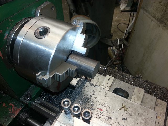
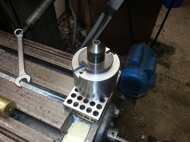
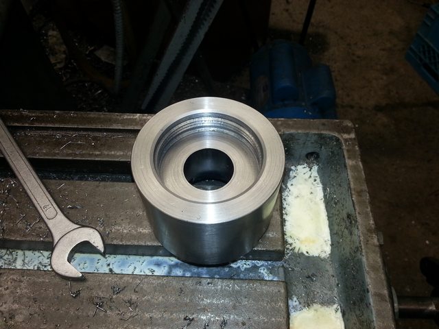
First step, I needed to make a quick modification to my mill to take the tooling I needed to use. My mill is a 100 year old Denbigh horizontal milling machine, that came with a relatively modern vertical attachment. The vertical attachment has a fantastically useful collet chuck, and an NMTB 40 spindle. The horizontal spindle is an odd taper. Does not match any known spec that I could find, including B&S, MT, and anything else I could look up. So if I was going to buy tools, it was going to be for the vertical attachment. Wanting to use those tools in horizontal mode too (because the vertical attachment doesn't have much space to the table), I needed an adapter. One $60 chunk of 4140 and a pile of hours taking light cuts on a lathe that wouldn't go slow enough, and this is what I've got.
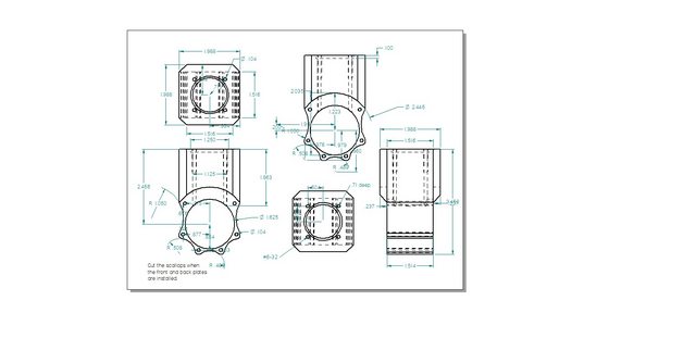
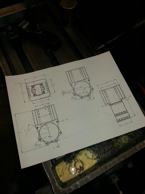
Today I gathered all of the material together, printed out the drawing for the block, and set out to square up the rough stock. I had noticed a few days ago that things on the mill seemed loose enough to cause a few thousandths of rock when the table was cranked over to one side. so I decided to address that. Yup, I can pivot the table 0.005" over 14". The mill came to me with every surface of it painted, including the ways. I stripped all of that off, but avoided going any harsher than paint stripper and an aluminum scraper, so it's still kinda settling in and smoothing off. So instead of spending the day squaring up the block and boring two perpendicular holes, I spent it pushing and pulling and adjusting gibs. Still a good day in the shop.
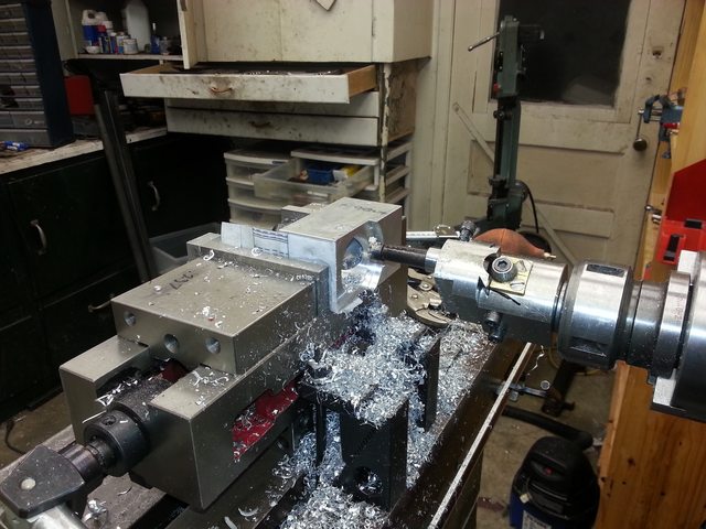
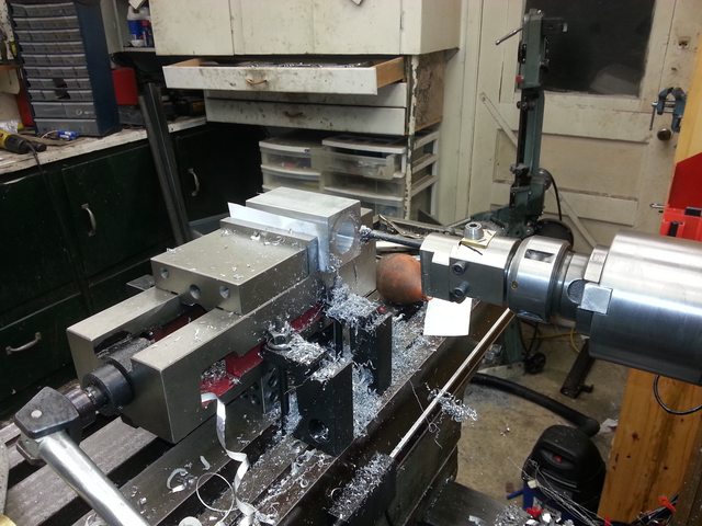
All set up and looking good, I took a skim off the top, flipped the block, stuck a round piece of plastic on the moving jaw, tightened the vise, and took another skim. It looked like it took more off of one side than the other, so I checked with a square. Yup, the fixed jaw needs bigger bolts, I can easily push it out of square and off the base a bit. I wish I could find a 3-4" Kurt. The base appears square though, so rather than using the round plastic I just tapped the block down into the vise so it sat flat on the base. Within 0.001 over 2", I'm ok with that. These are just going to be cooling fins later on. The more critical set up later on I won't need the vise for.
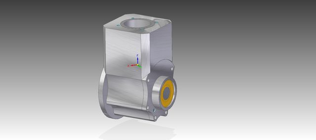
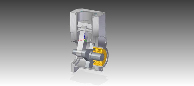
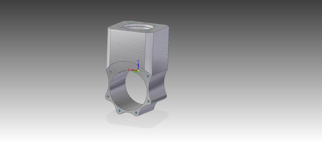
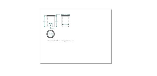
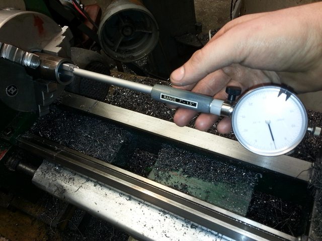
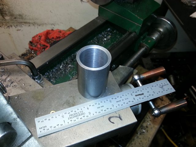
Here's the shape of the main block that'll come out of that chunk of aluminum. I don't have a need for an open rear anymore, but I think I'll bore it straight through and put a plate on the back so that I can put a plexiglas plate on the back and watch the oil level and splashing.
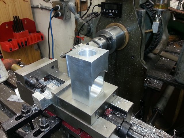
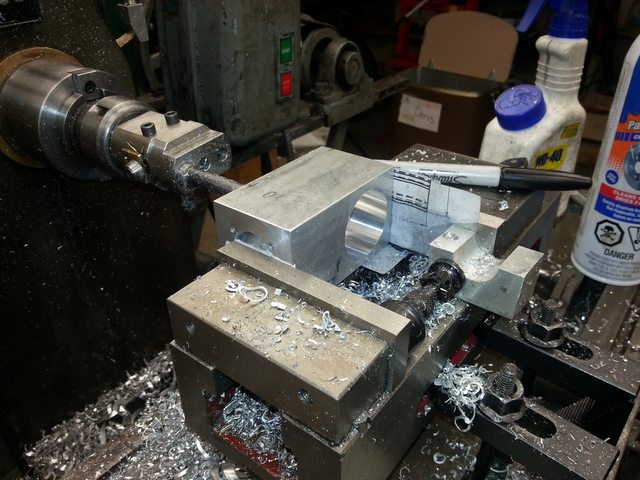
I'm planning on taking advantage of the horizontal mill in making perpendicular holes, by rotating the vertical head sideways to do the crankshaft bore, and without disturbing the setup, use the horizontal spindle to bore the cylinder (since I can lock the table axis and make it not succeptible to any table rock that might show up). That way I can get them perpendicular within the accuracy of the machine, which is quite good if I can keep the gibs where they need to be.
The horizontal spindle also makes it a piece of cake for squaring up the small end (the top and bottom, if oriented with a vertical cylinder). I just leave it on it's side in the vise where I did the last operation, rotate and indicate the vise in 90 degress, and install the fly cutter in the horizontal spindle. My vise isn't really deep enough to grab the bottom end of the block and face the top securely, especially with that tilting fixed jaw.
Now I'm equipped with a 10" lathe and an antique milling machine, and have built all of the tooling I'll need to do everything. It's time to start. A few weeks ago I put all of my knowlege and research together into a design, which I forgot to bring to work with me today to post for you. I wanted to document the build somehow, so I thought this might be a good place for it.
First step, I needed to make a quick modification to my mill to take the tooling I needed to use. My mill is a 100 year old Denbigh horizontal milling machine, that came with a relatively modern vertical attachment. The vertical attachment has a fantastically useful collet chuck, and an NMTB 40 spindle. The horizontal spindle is an odd taper. Does not match any known spec that I could find, including B&S, MT, and anything else I could look up. So if I was going to buy tools, it was going to be for the vertical attachment. Wanting to use those tools in horizontal mode too (because the vertical attachment doesn't have much space to the table), I needed an adapter. One $60 chunk of 4140 and a pile of hours taking light cuts on a lathe that wouldn't go slow enough, and this is what I've got.
Today I gathered all of the material together, printed out the drawing for the block, and set out to square up the rough stock. I had noticed a few days ago that things on the mill seemed loose enough to cause a few thousandths of rock when the table was cranked over to one side. so I decided to address that. Yup, I can pivot the table 0.005" over 14". The mill came to me with every surface of it painted, including the ways. I stripped all of that off, but avoided going any harsher than paint stripper and an aluminum scraper, so it's still kinda settling in and smoothing off. So instead of spending the day squaring up the block and boring two perpendicular holes, I spent it pushing and pulling and adjusting gibs. Still a good day in the shop.
All set up and looking good, I took a skim off the top, flipped the block, stuck a round piece of plastic on the moving jaw, tightened the vise, and took another skim. It looked like it took more off of one side than the other, so I checked with a square. Yup, the fixed jaw needs bigger bolts, I can easily push it out of square and off the base a bit. I wish I could find a 3-4" Kurt. The base appears square though, so rather than using the round plastic I just tapped the block down into the vise so it sat flat on the base. Within 0.001 over 2", I'm ok with that. These are just going to be cooling fins later on. The more critical set up later on I won't need the vise for.
Here's the shape of the main block that'll come out of that chunk of aluminum. I don't have a need for an open rear anymore, but I think I'll bore it straight through and put a plate on the back so that I can put a plexiglas plate on the back and watch the oil level and splashing.
I'm planning on taking advantage of the horizontal mill in making perpendicular holes, by rotating the vertical head sideways to do the crankshaft bore, and without disturbing the setup, use the horizontal spindle to bore the cylinder (since I can lock the table axis and make it not succeptible to any table rock that might show up). That way I can get them perpendicular within the accuracy of the machine, which is quite good if I can keep the gibs where they need to be.
The horizontal spindle also makes it a piece of cake for squaring up the small end (the top and bottom, if oriented with a vertical cylinder). I just leave it on it's side in the vise where I did the last operation, rotate and indicate the vise in 90 degress, and install the fly cutter in the horizontal spindle. My vise isn't really deep enough to grab the bottom end of the block and face the top securely, especially with that tilting fixed jaw.
Last edited:


![DreamPlan Home Design and Landscaping Software Free for Windows [PC Download]](https://m.media-amazon.com/images/I/51kvZH2dVLL._SL500_.jpg)


")