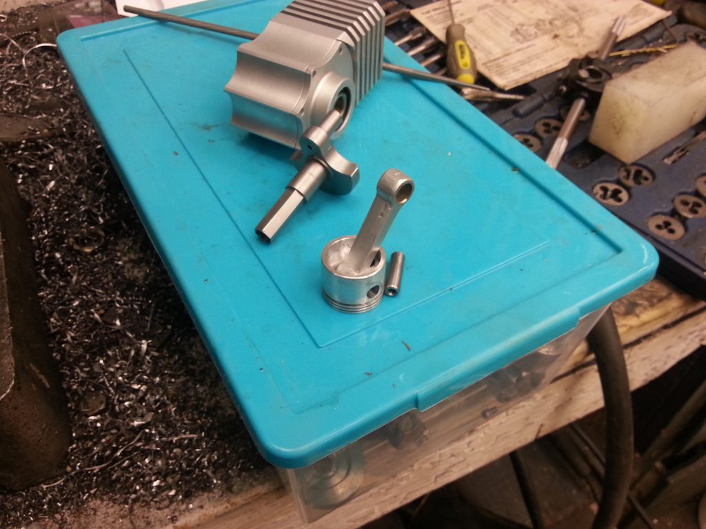
A few things have been delaying this project.
1) I needed to make some tools to radius the under side of the head
2) It's summer and I own a motorcycle
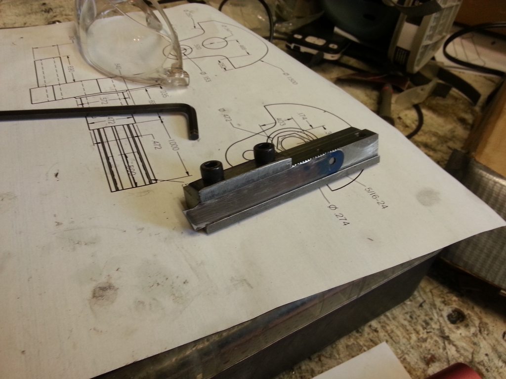
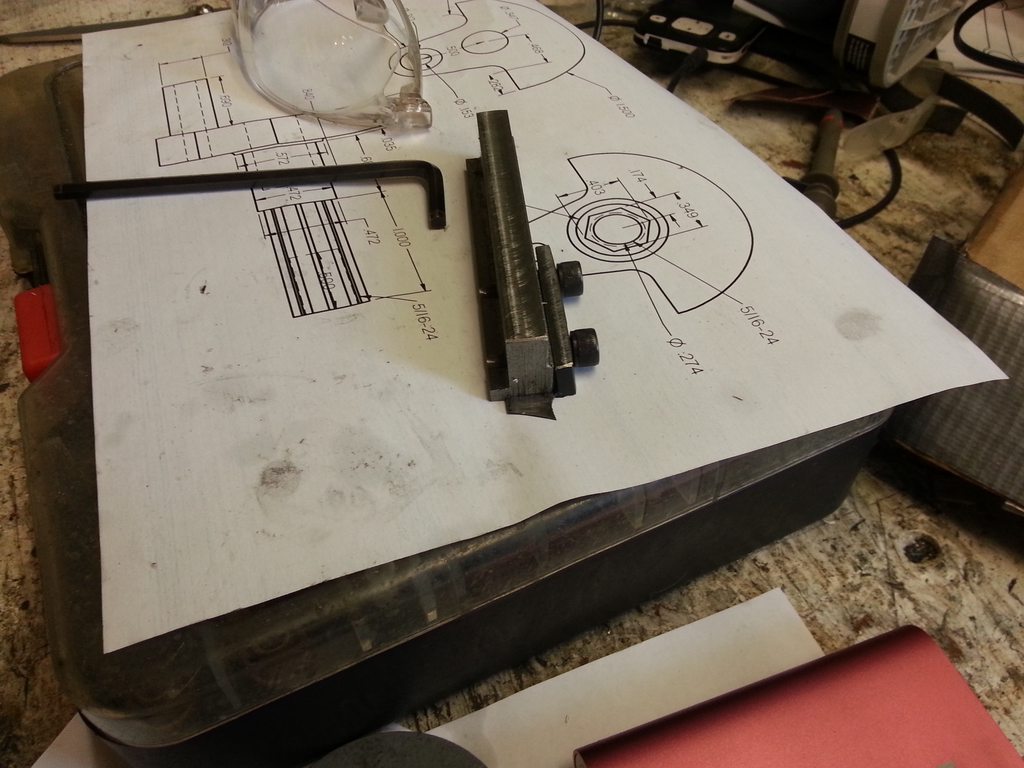
But I've made a little progress on a radius tool. I wanted to make it fit many types of jobs, so I needed a lot of adjustability and the ability to turn concave as well as convex radiuses.
I got this idea from somewhere else on this forum, but I don't remember where. Apologies! In any case, I can't take credit for it, I only modified the idea for the bearing.
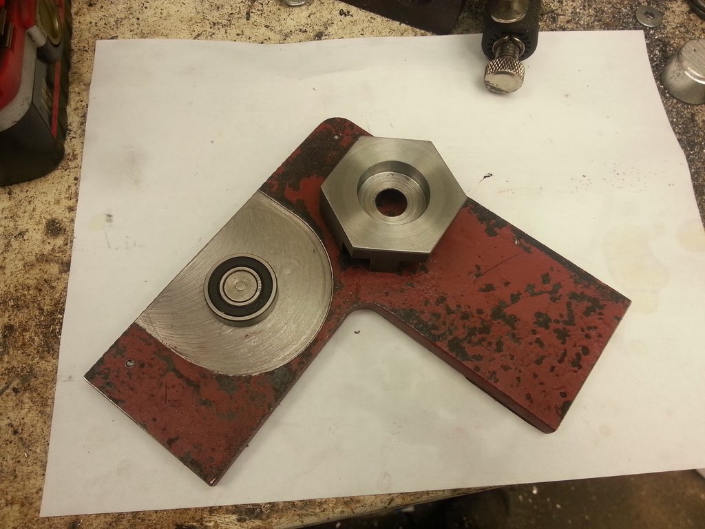
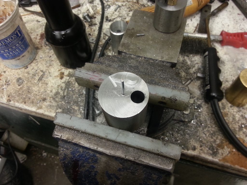
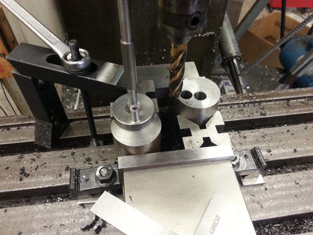
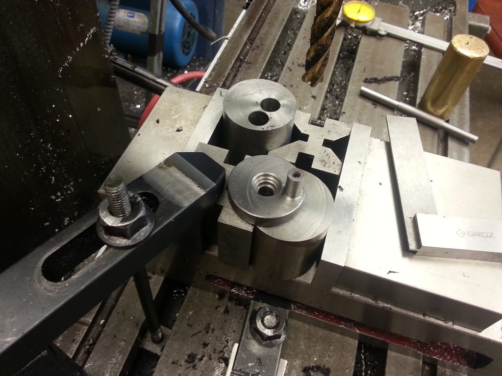
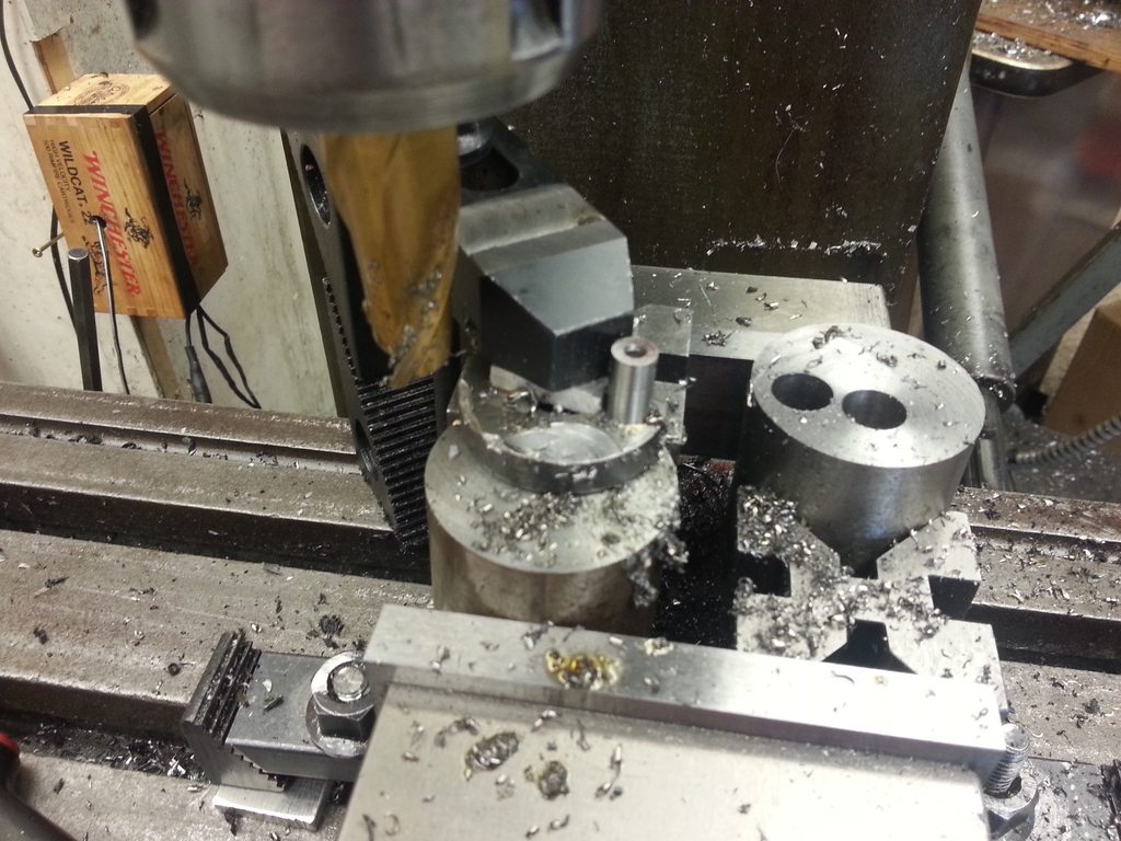
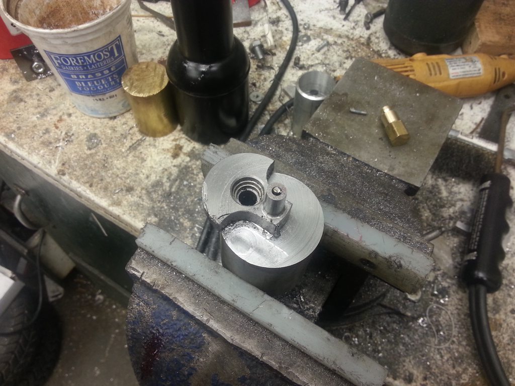
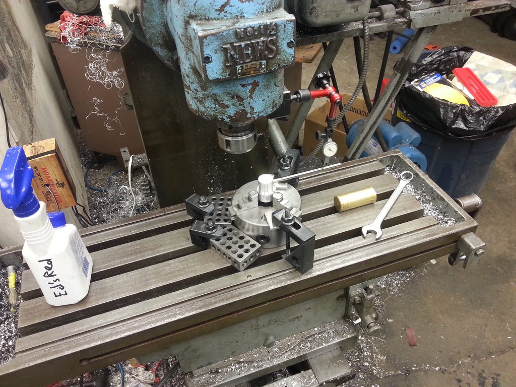
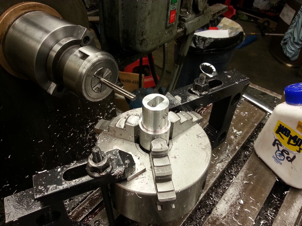
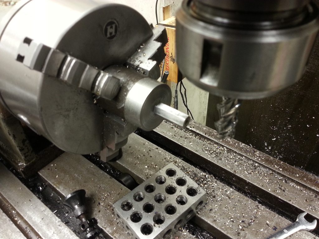
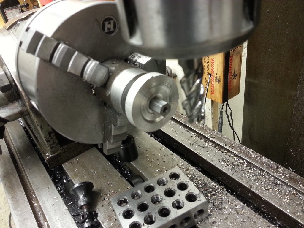
I didn't finish the whole top because it's some nasty very hard tractor parts that is cold rolled and warps like a banana. I did the top first, then flipped it over and cut some clearance on the bottom so I had 3 pads I could finish, instead of doing a finish cut over the whole surface. It worked well enough but my surface finish isn't great. It'll work fine. Pressed in a stud, pressed on a bearing, and had a wiggle-fit for the bearing into the under side of the tool arm holder. I loctite'd the block to the bearing.
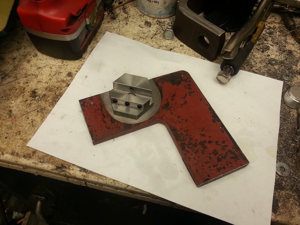
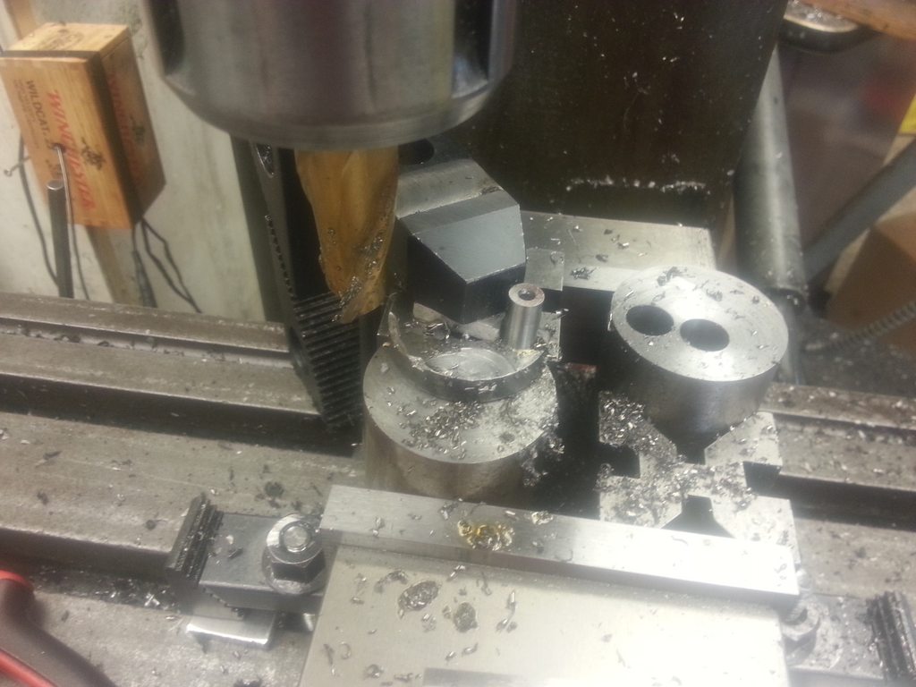
1/2" slot 1/2" deep right down the center, and some clearance for set screws. This sets the radius of the curve. The slot is about 0.025" wider than 1/2", so when using 1/2" material, I could have a feeler gauge shim that the set screws would bite into, instead of biting into the arm and causing problems when trying to make tiny adjustments.
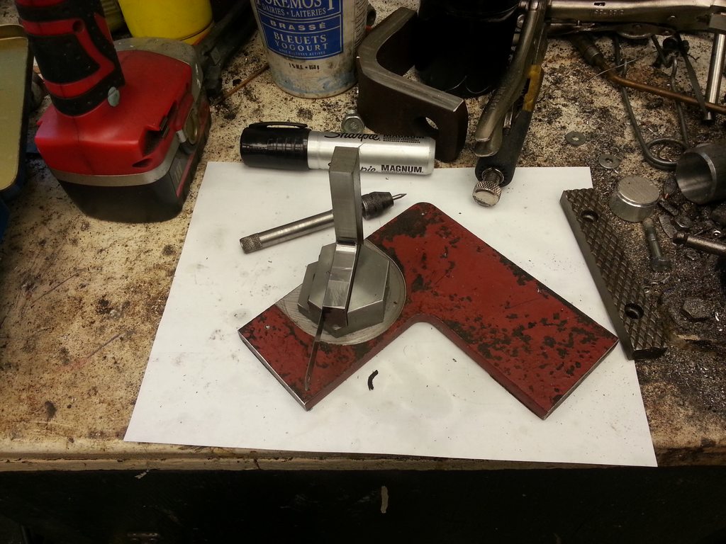
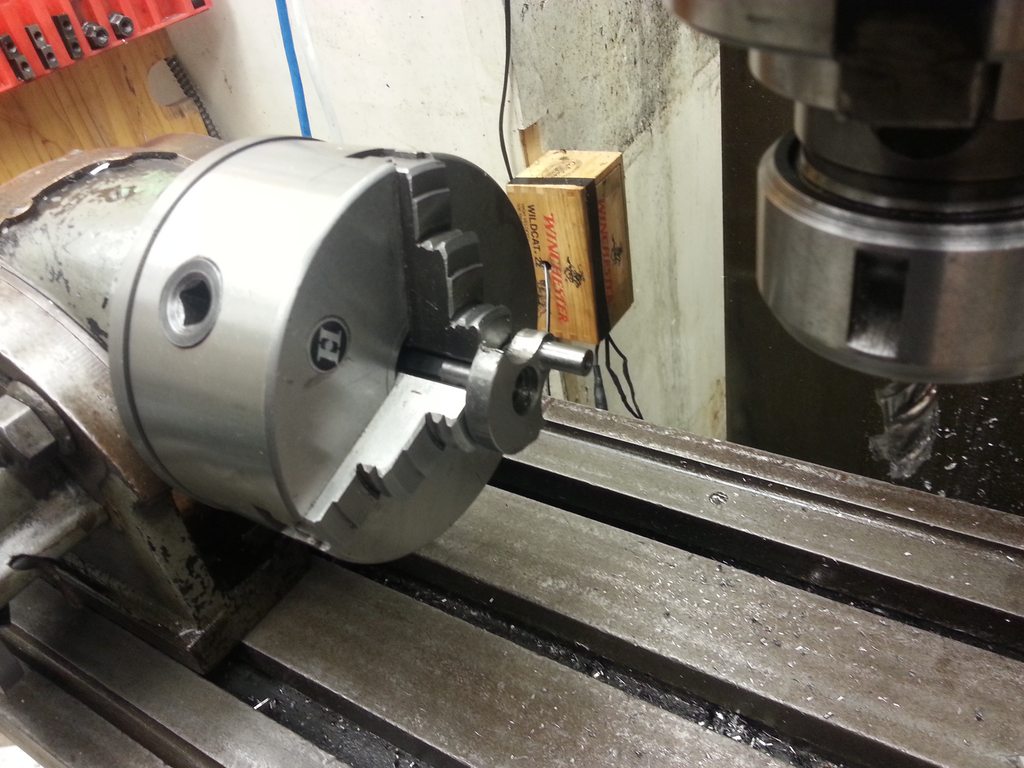
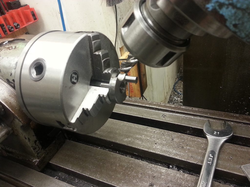
The tool bit holder arm in place. I brought it to the lathe, stuck a scriber in the spindle, and scratched where the tool bit would go, and drilled/reamed a 3/8" hole at that location. Then I drilled and tapped from the top, to insert a set screw.
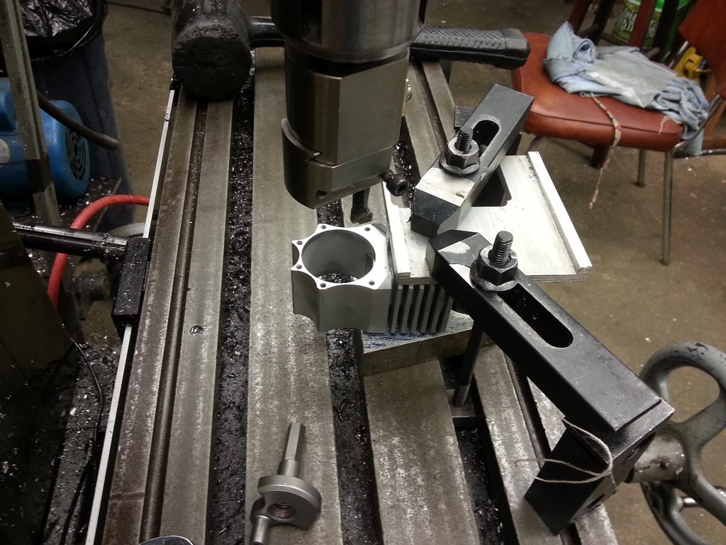
I just grind toolbits from broken 3/8" endmills. Flip the tool bit end for end to switch between concave and convex radii. The whole mess bolts down to the cross slide of my lathe with the compound removed.
Next I'll consider order of operations to make the head. Probably going to go something like this:
- Bring a block to size, but about 3/4" taller than it needs to be.
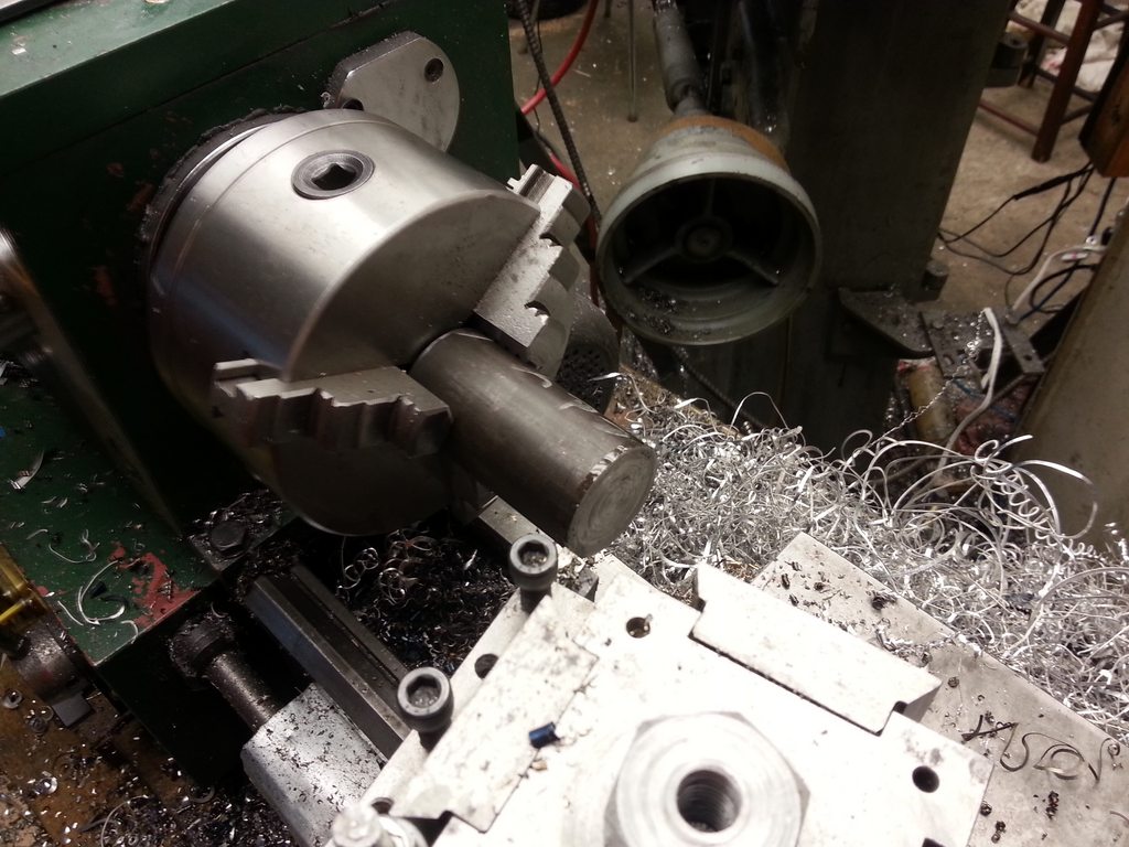
- Hold it in the lathe 4 jaw, and turn the corners.
- Turn the concave under side.
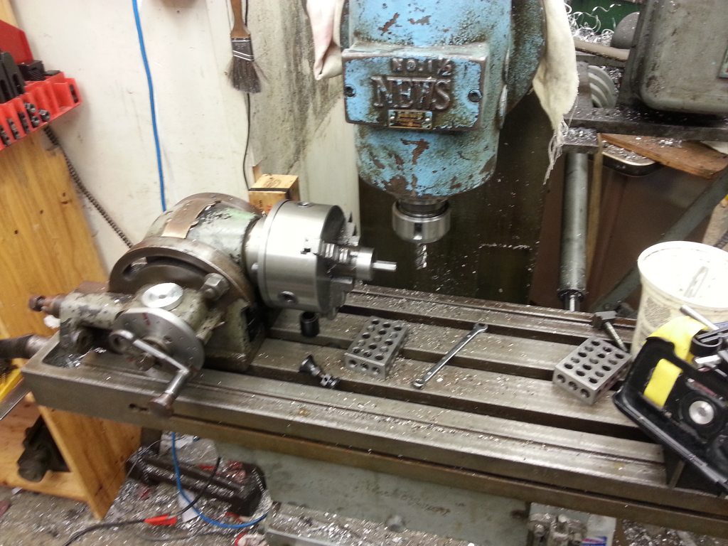
- Remove from lathe, and bolt down to the mill table piston-side down, with the mill in horizontal mode. Indicating off of the table and the edge of the part, drill/ream the camshaft bearing locations.
- Reinstall the vertical head, and drill/counterbore the head hold down bolt holes.
- Remove the head and make a fixture that sits at the correct angle and has a register for the ring on the under side of the head, as well as 4 threaded holes.
- Bolt the head to the fixture, and fly cut the angled top of the head (which will be located at the centerline of the camshaft holes).
- While still in the fixture, mill the pockets for the valve train to fit inside, and drill/ream the valve guide and seat hole.
- Flip the head 180 degrees and repeat on the other side.
- Flip the head 90 degrees and complete the spark plug hole features.
The trickiest part is figuring out how to locate the features based on the edges of the tilted head block. I may have to get CAD involved so I can indicate off of known locations of the fixture instead.
Enough stuff to do that it may stretch throughout the summer months.


![DreamPlan Home Design and Landscaping Software Free for Windows [PC Download]](https://m.media-amazon.com/images/I/51kvZH2dVLL._SL500_.jpg)


