You are using an out of date browser. It may not display this or other websites correctly.
You should upgrade or use an alternative browser.
You should upgrade or use an alternative browser.
Dave's twin
- Thread starter Dave G
- Start date

Help Support Home Model Engine Machinist Forum:
This site may earn a commission from merchant affiliate
links, including eBay, Amazon, and others.
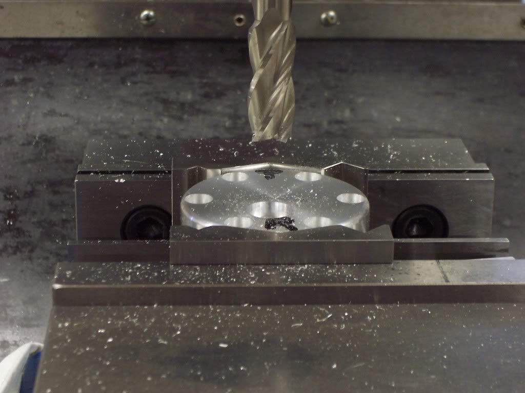
Time for the cylinder yoke now. A piece of 6061 al. was cut off and the sides were milled to size. The first face was milled with a facing mill and then the part was flipped in the vise and then faced to size and checked to make sure the faces were parallel. A .500" dia construction hole was reamed on center after the part was indicated to find center in "X"&"Y". The holes for the cylinders were bored next to 1.501" dia to leave .001" clearance for the cylinder liners.
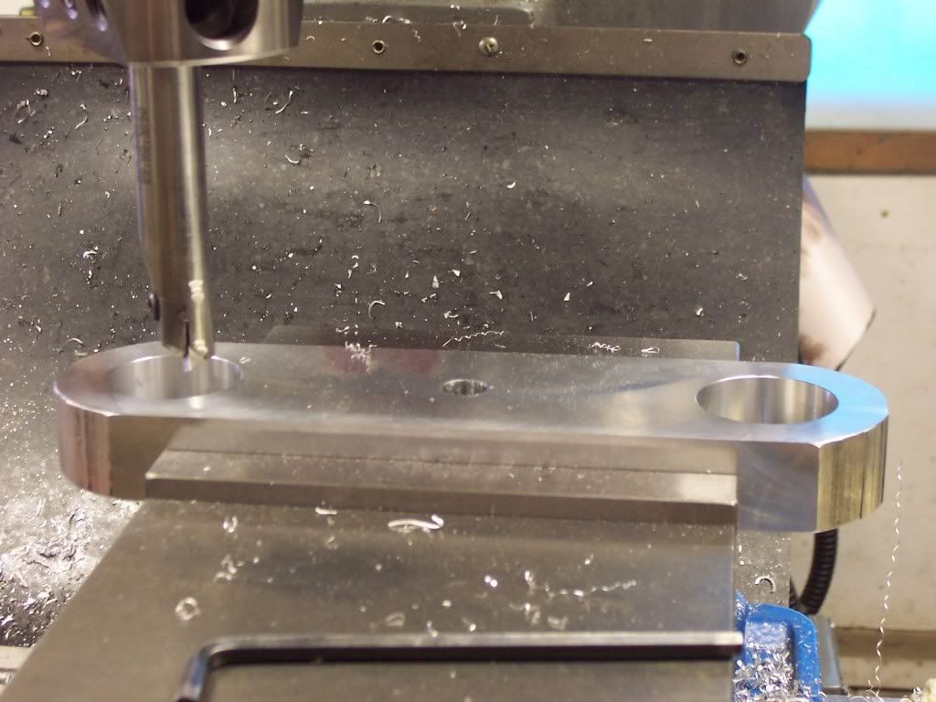
Each cylinder will be attached to the yoke with 8 10-32 capscrews. The counter-bored holes for these are drilled next on a 2" bolt circle.
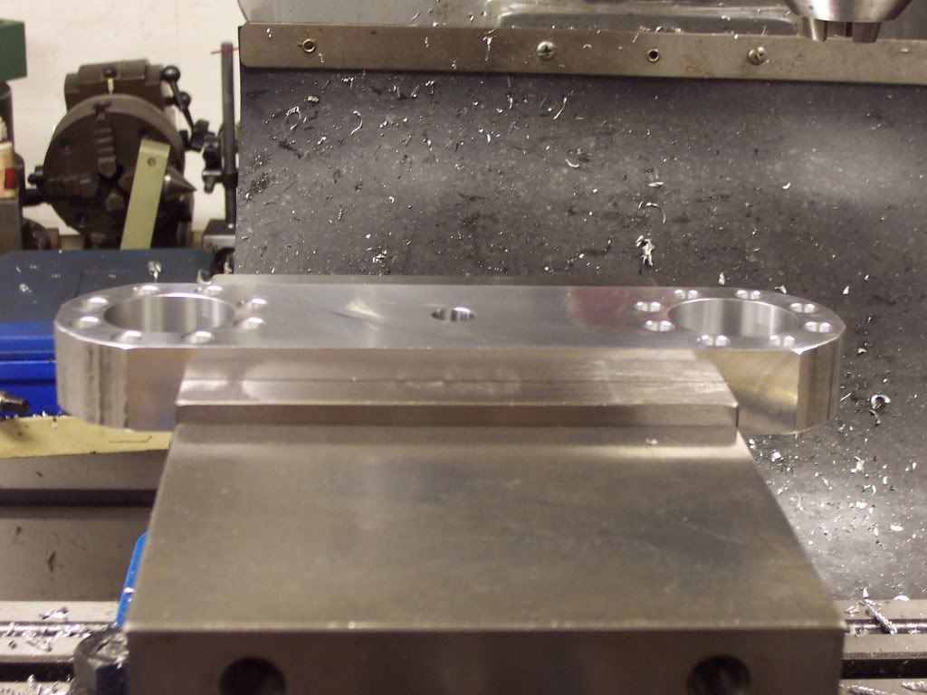

Each cylinder will be attached to the yoke with 8 10-32 capscrews. The counter-bored holes for these are drilled next on a 2" bolt circle.

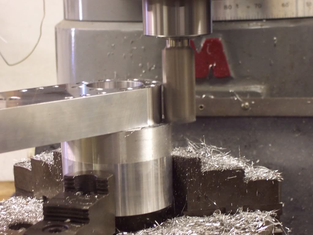
You will notice that I sawed the corners off of the part before boring the holes. The ends of the part will have a full radius milled on them. If I were to wait until after I bored the holes to remove this stock my holes wouldn't be round anymore. Anytime I have to bore a hole to size, I make sure I remove the stock from around the hole first to relieve the stress. To radius the ends I had to take a piece of stock and tap 8 10-32 holes in it on a 2" dia bolt circle to fit the yoke. The stock was placed in the rotary table on the mill and indicated in. The part was bolted to the stock and the ends were milled using the rotary table to generate the radius. Both ends are done this way.
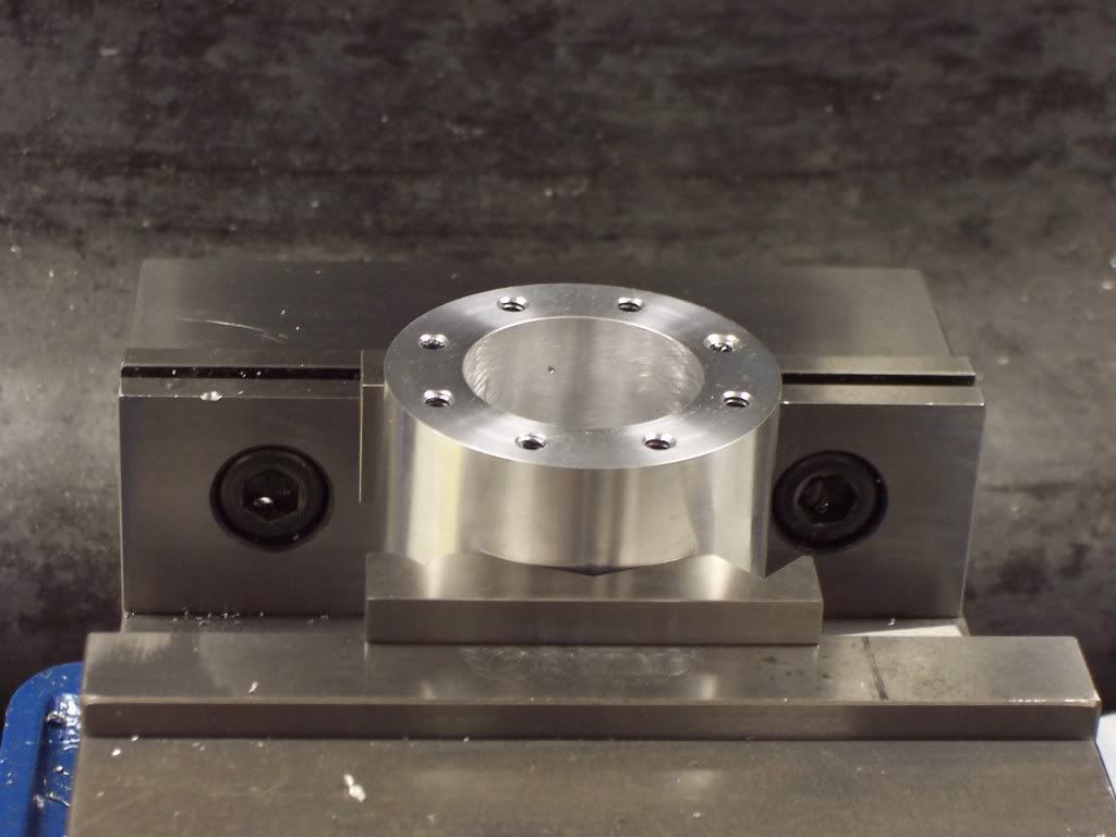
And a pic of the finished yoke. The cylinder holes are bored to size and the mounting bolt holes are drilled and counter-bored.
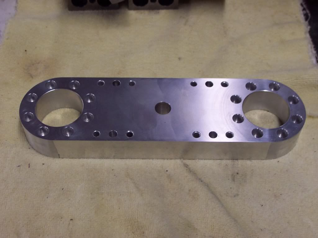

And a pic of the finished yoke. The cylinder holes are bored to size and the mounting bolt holes are drilled and counter-bored.

2 more holes and there wouldn't be anything left. Nice!
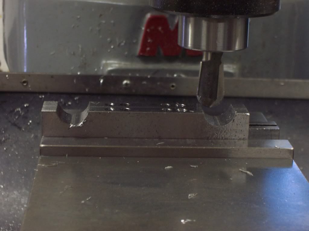
I need to make the supports for the yoke next. For this I found 2 pieces of CRS .5" thick. They were squared up on the mill and then surface ground to make them flat. I also ground the edges square using my angle plate the same as I did the gearcase. The reason for this is when I drill and ream the holes for the dowel pins I want them centered in the part exactly. The holes go in the edges of the parts and must locate the yoke correctly. After reaming the dowel holes and tapping the mounting bolt holes the part was set up in the mill vise to remove some of the bulk. To start with I used a ball end mill to give me a radius to blend to.
Next I clamped the parts to my angle plate that is bolted to the mill table. An angle of 30 degrees as used. The excess stock is milled away now on each end.
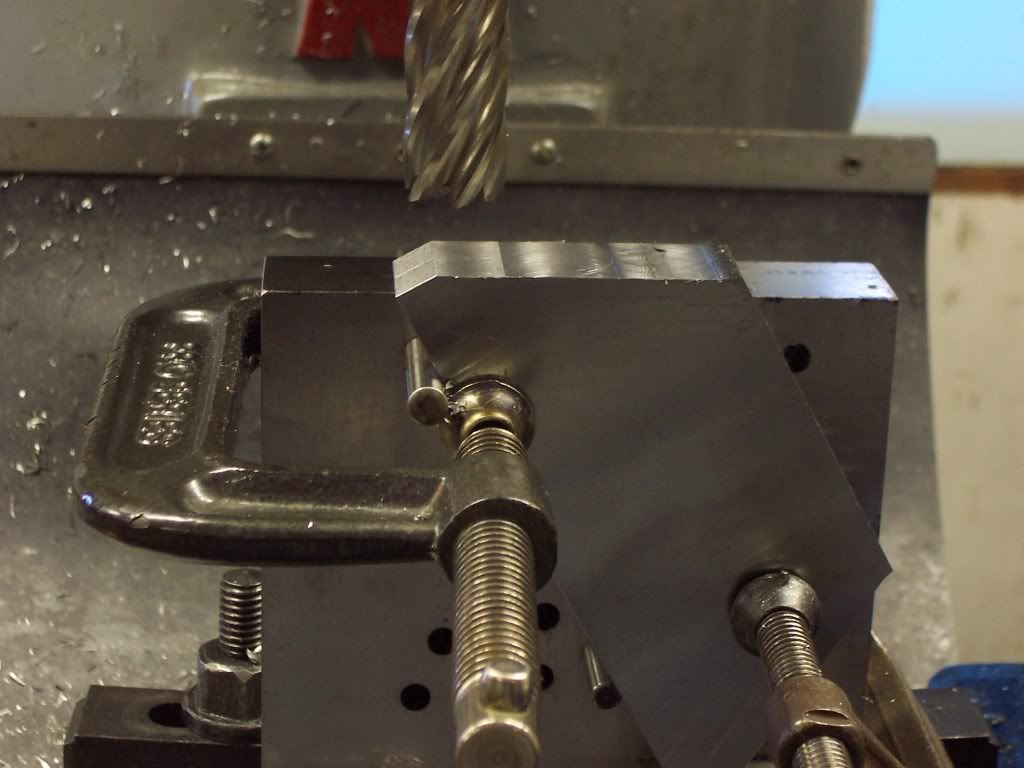

Next I clamped the parts to my angle plate that is bolted to the mill table. An angle of 30 degrees as used. The excess stock is milled away now on each end.


$99.99
AHS Outdoor Wood Boiler Yearly Maintenance Kit with Water Treatment - ProTech 300 & Test Kit
Alternative Heating & Supplies

$37.82
$49.99
Becker CAD 12 3D - professional CAD software for 2D + 3D design and modelling - for 3 PCs - 100% compatible with AutoCAD
momox Shop

$19.15
$29.95
Competition Engine Building: Advanced Engine Design and Assembly Techniques (Pro Series)
MBC Inc.

$599.00
$649.00
FoxAlien Masuter Pro CNC Router Machine, Upgraded 3-Axis Engraving All-Metal Milling Machine for Wood Acrylic MDF Nylon Carving Cutting
FoxAlien Official

$49.95
$55.99
DjuiinoStar Hot Air Stirling Engine Assembly Kit: Spend 30 Minutes to Build Your Own Stirling Engine
djuiinostar

$45.99
Sunnytech Mini Hot Air Stirling Engine Motor Model Educational Toy Kits Electricity HA001
stirlingtechonline

$26.89
$34.99
Peachtree Woodworking Supply Bowl Sander Tool Kit w/Dual Bearing Head & Hardwood Handle, 42 Pieces Wood Sander Set, 2 Hook & Loop Sanding Disc Sandpaper Assortment, 1/4 Mandrel Bowl Sander
Peachtree Woodworking Supply Inc
![DreamPlan Home Design and Landscaping Software Free for Windows [PC Download]](https://m.media-amazon.com/images/I/51kvZH2dVLL._SL500_.jpg)
$0.00
DreamPlan Home Design and Landscaping Software Free for Windows [PC Download]
Amazon.com Services LLC
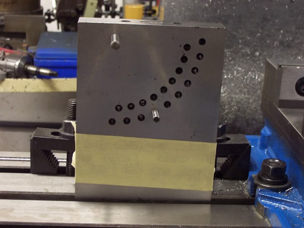
A pic of my angle plate. The array of holes are for placing parts at 5 degree increments by placing the dowel pins in different holes. I didn't make this angle plate, it was made by one of my former co-workers and I bought it at his sale last fall. I can see I will get alot of use out of it.
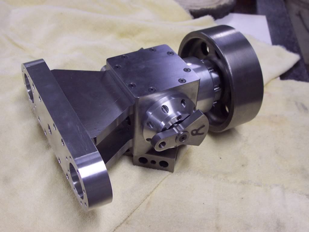
I drilled and reamed the dowel holes in the gearcase to match the supports and drilled clearance holes for the mounting bolts. Everything was cleaned well and assembled to see how it looked.
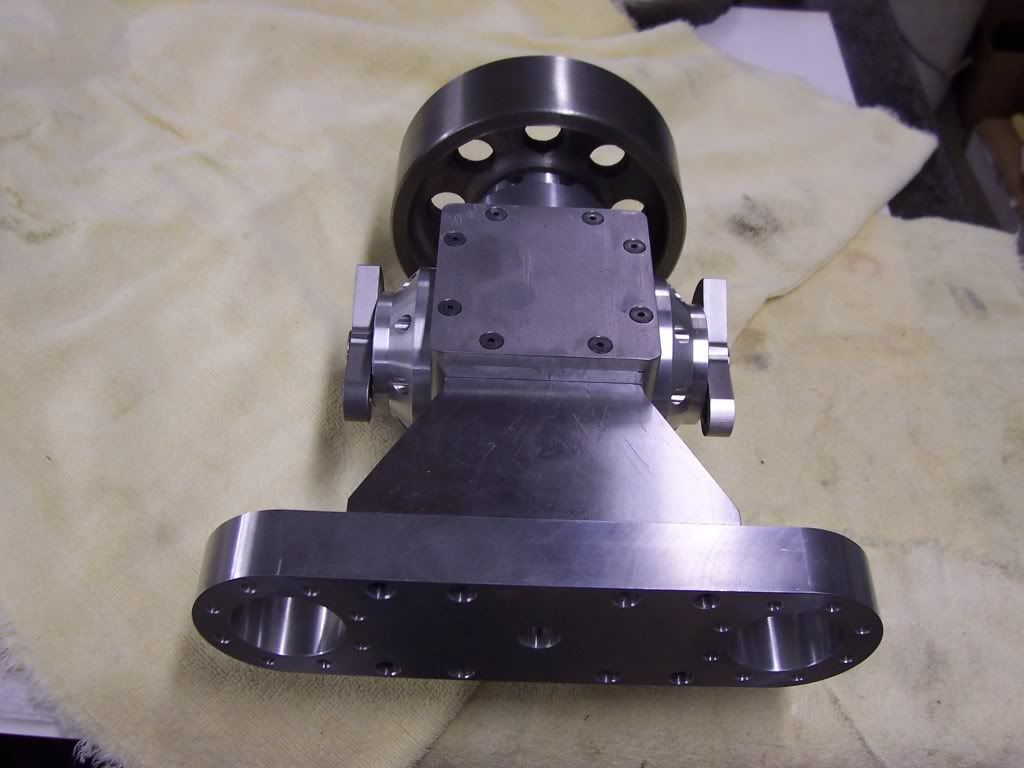
And from a different angle.
The cylinders and liners come next. The cylinders will be made from 6061 al and the liners from 12L14.

I drilled and reamed the dowel holes in the gearcase to match the supports and drilled clearance holes for the mounting bolts. Everything was cleaned well and assembled to see how it looked.

And from a different angle.

The cylinders and liners come next. The cylinders will be made from 6061 al and the liners from 12L14.
I'm a big Who fan but I'm not too keen on Drs. Pete LOL Do Darleks have machine guns or Ray guns? If this thing doesn't run maybe I can sell it to a local fisherman to keep his boat in place. Anyways, theres alot of extra bulk on the supports and the yoke to come off yet. I will need to mount the hall effect sensor and a coolant pump to the supports at some point and then I will know where to remove the extra stock. The cylinders shouldn't take too long to make but the cylinder heads will be a challenge. I'm going to have to think about a base soon also. I hope you can get an idea of where I'm going with this thing now. Soon it will look more like an engine, I hope.
Whatever it turns out to be, i'm enjoying watching it take shape.
I got tied up with a paying customer for a few days so I haven't had time to do much lately. I did get the cylinders started.
Heres a pic of the boring of the cylinders. I bored the ID to give me a press fit of .0015" on the sleeve.
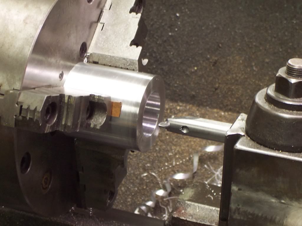
I had to bore a groove to form a water jacket around the sleeve next. I used a boring bar with a grooving tool insert for this.
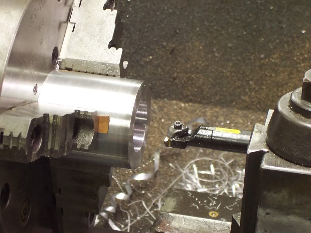
Heres a pic of the boring of the cylinders. I bored the ID to give me a press fit of .0015" on the sleeve.

I had to bore a groove to form a water jacket around the sleeve next. I used a boring bar with a grooving tool insert for this.

I went ahead and drilled and tapped the mounting holes in the cylinders next. The cylinders were setup in the mill vise and indicated true. The holes were located with the DRO after using trig to find the locations.
The cylinder sleeves were made from 12L14 steel. The ODs were turned to within .020" of finished size and the bores were finished leaving .002" to hone after assembly. After finishing the bores the ODs were finished to size and then parted off. The sleeves were put in the freezer overnight and the cylinders were put on my hotplate the next morning to warm up. The sleeves were slid into position in the cylinders with a light coat of Locktite and let to cool.
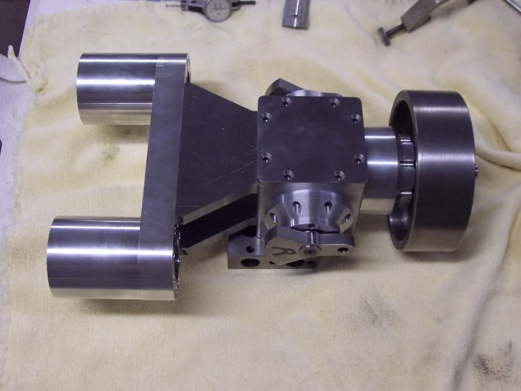
Heres a pic of the cylinders installed in yoke.
I'll start on the cylinder heads next.

The cylinder sleeves were made from 12L14 steel. The ODs were turned to within .020" of finished size and the bores were finished leaving .002" to hone after assembly. After finishing the bores the ODs were finished to size and then parted off. The sleeves were put in the freezer overnight and the cylinders were put on my hotplate the next morning to warm up. The sleeves were slid into position in the cylinders with a light coat of Locktite and let to cool.
Heres a pic of the cylinders installed in yoke.

I'll start on the cylinder heads next.
Thanks guys, I've got some work done on the heads and will post the pics soon. I got some more real work dropped off at my place last night which will keep me busy until early next week. I have a friend that works for his brother-in-law in a machine shop and when they get real busy they funnel a little work my way. I'm glad I can help as they have just started and are doing well so far.
After the heads are finished I will go ahead and make the valve cages, valves, retainers, etc. I will try to post the making of these components as I move forward. I haven't decided on a coolant system yet or where to mount it. What does the forum think, radiator, screen cooled or a coolant tank? My grandson just woke from his nap and he looks hungry so I have to go, Dave
After the heads are finished I will go ahead and make the valve cages, valves, retainers, etc. I will try to post the making of these components as I move forward. I haven't decided on a coolant system yet or where to mount it. What does the forum think, radiator, screen cooled or a coolant tank? My grandson just woke from his nap and he looks hungry so I have to go, Dave
For the heads I cut 2 pieces of 6061 al 2.5" in dia at 1.1" in length. I chucked up on the OD and faced the part then turned the OD to cleanup.
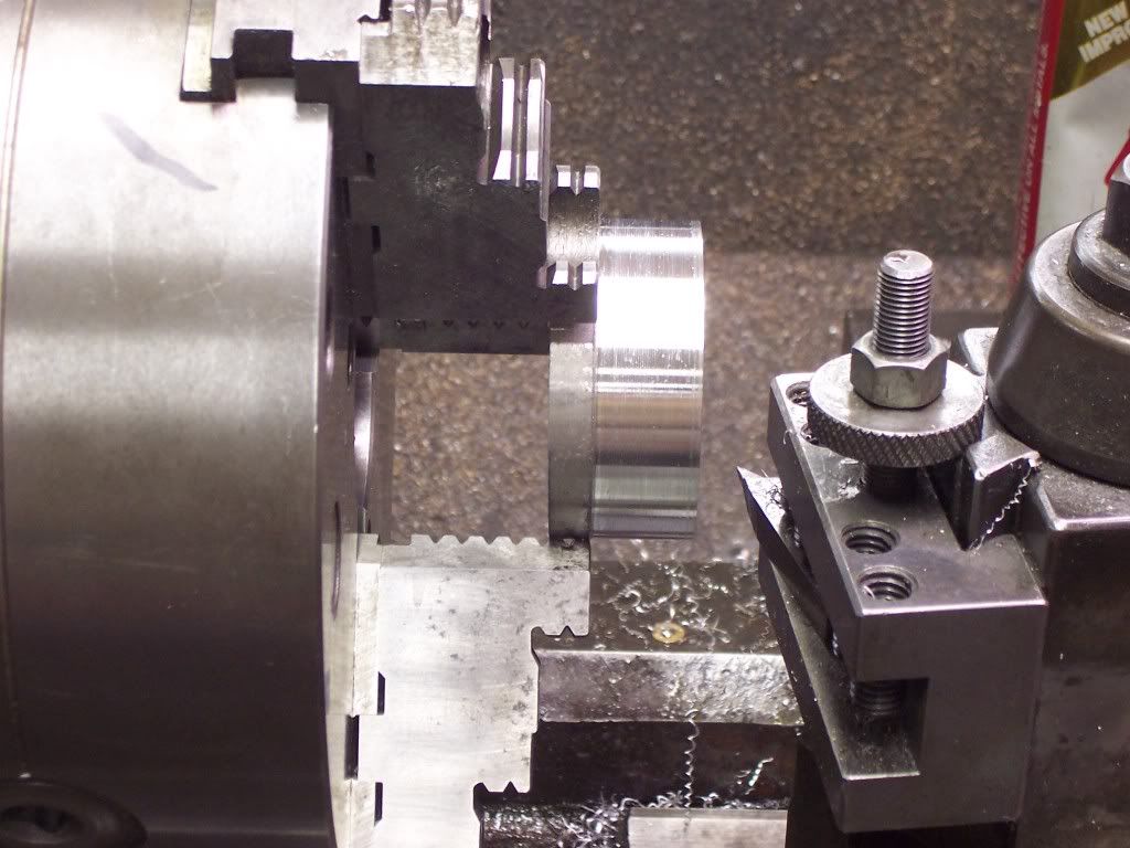
Next the parts were turned around in the chuck and faced to cleanup. I used 3 pieces of shim to keep the part from being marked by the chuck jaws. The thickness was measured in 3 places and then tapped witha small hammer until the faces were running true with each other and then the thickness was finished at .750". Before removing from the lathe I used a toolbit with a radius ground on it to form a radius on the corner.
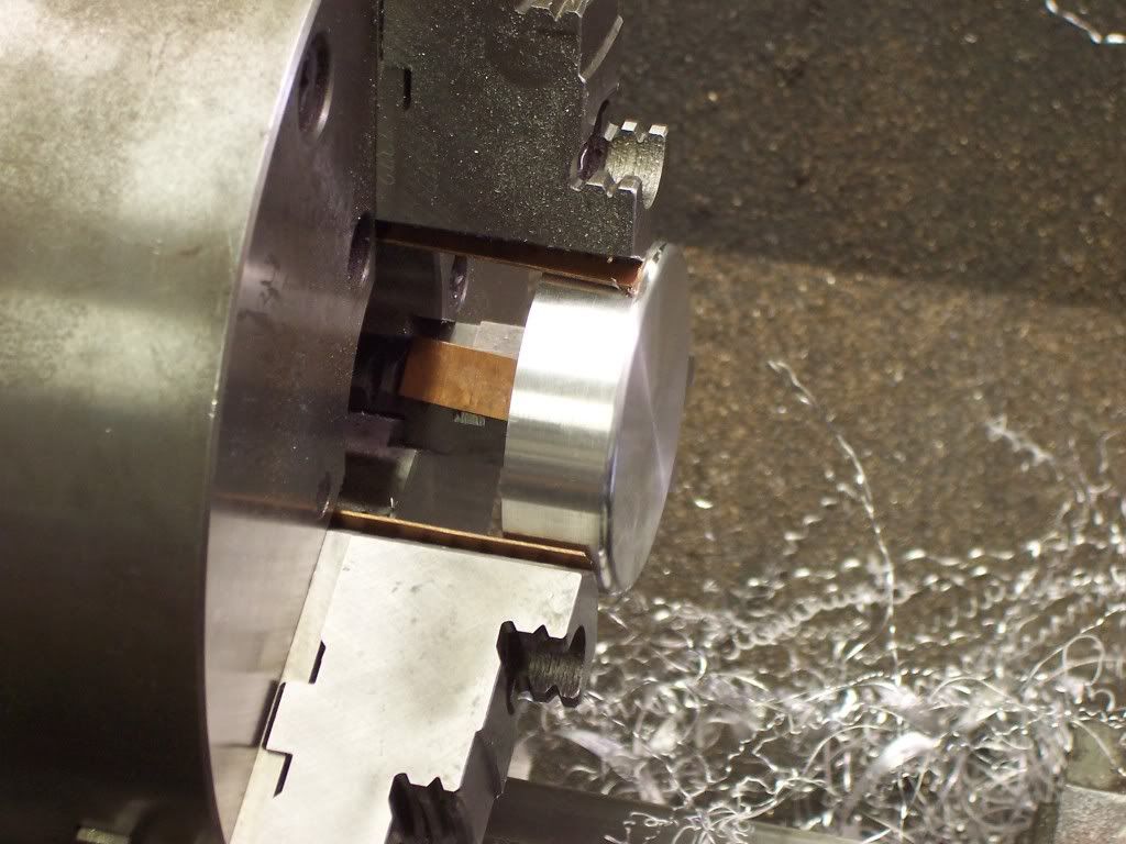

Next the parts were turned around in the chuck and faced to cleanup. I used 3 pieces of shim to keep the part from being marked by the chuck jaws. The thickness was measured in 3 places and then tapped witha small hammer until the faces were running true with each other and then the thickness was finished at .750". Before removing from the lathe I used a toolbit with a radius ground on it to form a radius on the corner.

The heads were clamped in the mill vise with the outside surface up supported by parallels underneath. The OD was indicated in with the spindle and the 6 bolt holes were spot drilled.
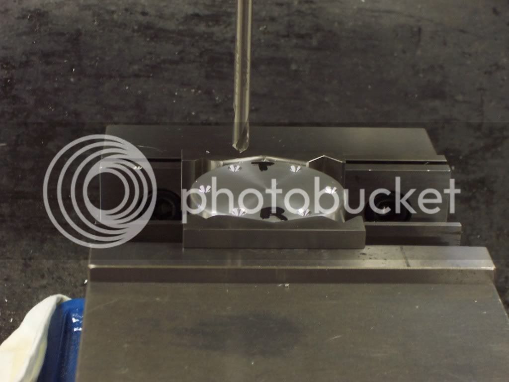
The clearance holes were drilled for the 1/4" bolts next.
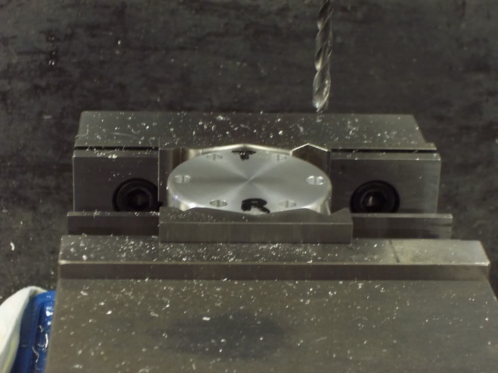
A pic of the holes counter-bored for the capscrews.
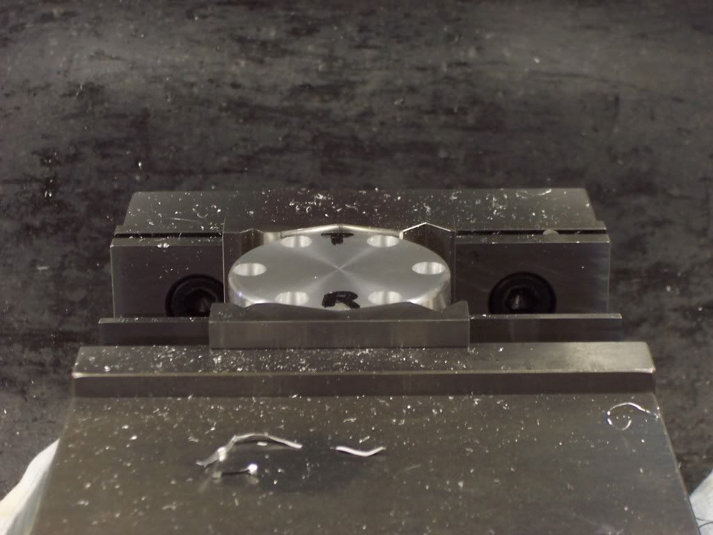

The clearance holes were drilled for the 1/4" bolts next.

A pic of the holes counter-bored for the capscrews.

I needed to make a fixture to mount the heads to for the next operations. This was just a block of CRS big enough to mount the head to machined square and ground flat. 6 1/4-20 holes were tapped on the correct bolt pattern to match the heads.
The heads will be cooled with holes drilled through them. The holes will intersect the exhaust valve cage and will exit the head from the top. The coolant will come from a port drilled through the cylinder into the jacket surrounding the sleeve.
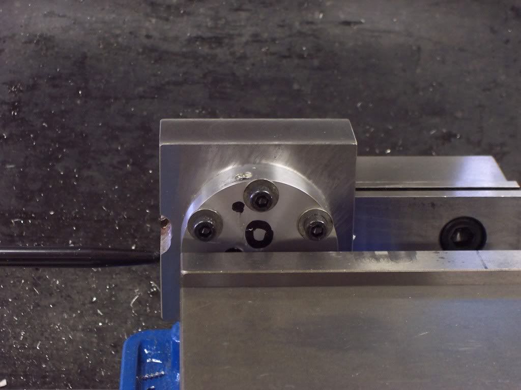
Once all the coolant ports were drilled the heads were flipped over on the fixture and remounted in the mill vise so the the holes for the valve cages could be machined next. After indicating the OD to find center the holes for the cages were drilled and reamed .3125" dia through. Next I used a 31/64 endmill to take out most of the stock for the cage itself going .625" deep
in both valve locations.
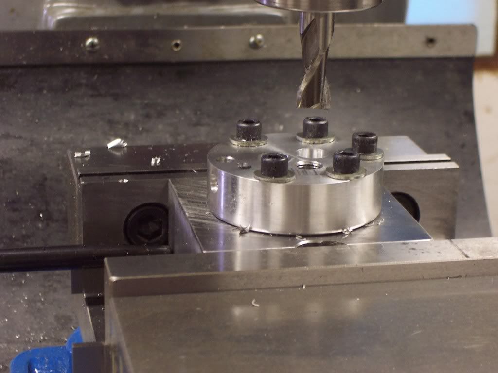
The heads will be cooled with holes drilled through them. The holes will intersect the exhaust valve cage and will exit the head from the top. The coolant will come from a port drilled through the cylinder into the jacket surrounding the sleeve.

Once all the coolant ports were drilled the heads were flipped over on the fixture and remounted in the mill vise so the the holes for the valve cages could be machined next. After indicating the OD to find center the holes for the cages were drilled and reamed .3125" dia through. Next I used a 31/64 endmill to take out most of the stock for the cage itself going .625" deep
in both valve locations.

Similar threads
- Replies
- 35
- Views
- 3K
- Replies
- 11
- Views
- 1K


![MeshMagic 3D Free 3D Modeling Software [Download]](https://m.media-amazon.com/images/I/B1U+p8ewjGS._SL500_.png)


