Dave's twin

Home Model Engine Machinist Forum

Help Support Home Model Engine Machinist Forum:

This site may earn a commission from merchant affiliate links, including eBay, Amazon, and others.
Heres a pic of cutting the Woodruff keyway. The shaft is held in the vise jaws using V-blocks. I used my angle plate on the outboard end for support. The center in "Z" was found by using a piece of .004" thick paper between the cutter and the major dia of the part. The knee was raised until the paper walks out from between cutter and the part and then Zero was set. I next moved the knee up in .001" increments until it lightly touched the part. This was done with the cutter rotating and I reset my Zero. Now I moved the knee up half the dia of my shaft and half the thickness of the cutter to put me on center.
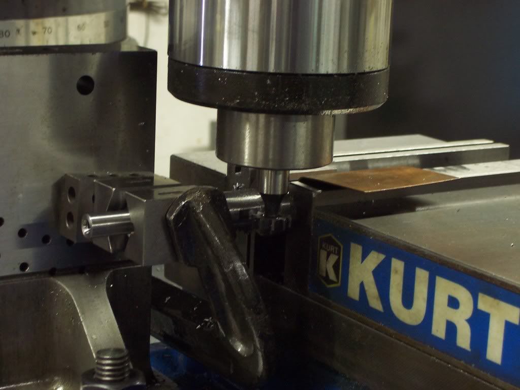
102_1069.jpg


The info for the depth of cut was taken from my Machinery Handbook.
 
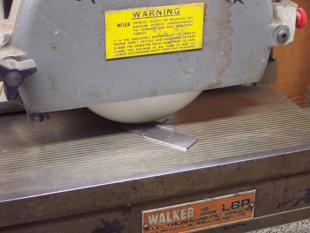
I had to grind .001" off the thickness of the Woodruff key to get it to fit the keyway. I always block the part to be ground with parallels to keep it from flying off the table when grinding.

102_1070.jpg


Hi Dave, looking great so far! Love your finishing, I never get my parts looking so shiny and without machine marks..... :bow:

Seems that you have some nice (and serious) equipment in your shop, if possible could you post some pictures of the grinding machine you build? I have a clarcson tool grinder and I am thinking to make some additions to that machine so I can use it as a grinding machine too.

Have fun, regards Jeroen
 
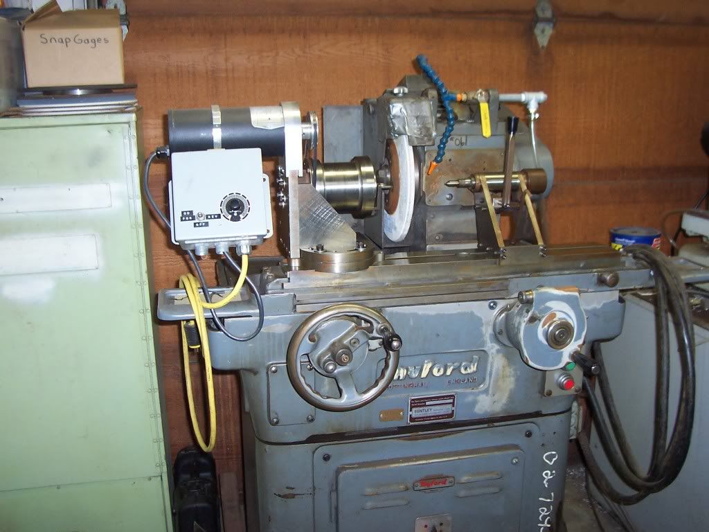
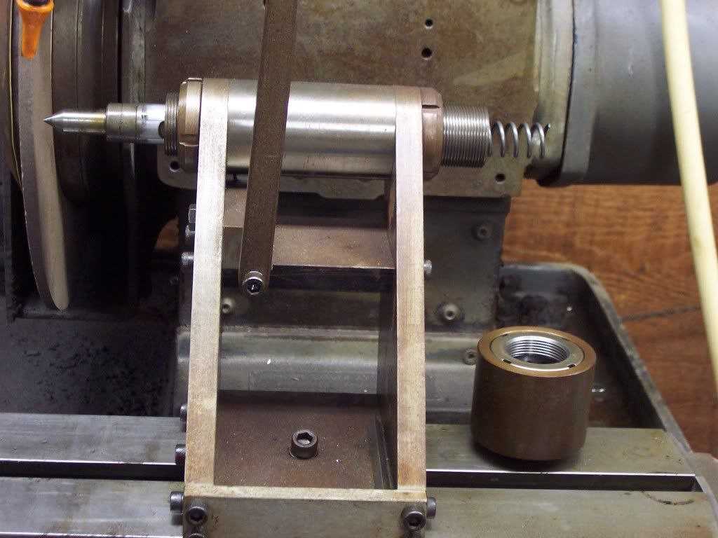
Hi Jeroen, Thanks for the support. My OD grinder is a Myford that I bought used at a used machinery dealer. It didn't have a headstock or a tailstock so I had to make them. The headstock has 2 angular contact bearings on the outboard end and a precision ball bearing on the inboard end. The shaft that the bearings ride on has a tapered hole in one end for a dead center and is bolted to the support on the other. When making the supports for the shaft I tried to keep everything as square as I could get it. The housing for the outer races of the bearings was probably the hardest part to make. The outer race bores had to be very concentric so I ground them on a bore grinder using shoes. When grinding between centers the housing is used just as a driver for the workpiece but I can also bolt a 5" dia magnetic chuck to it for other applications.

The tailstock is just a spring loaded spindle with a tapered hole in it for a dead center. There is an adjustment for the spring tension on the center.

The headstock is powered by a DC variable speed motor connected with a v-belt.

When OD grinding I will normally use a snap gage to check for size and to be able to correct for taper in the part. On the shaft I just made I held the dias to within .0001" in size and taper for the length of the surface. I grind all my crankshaft journals and any dia I want to hold close.
102_0996.jpg

 
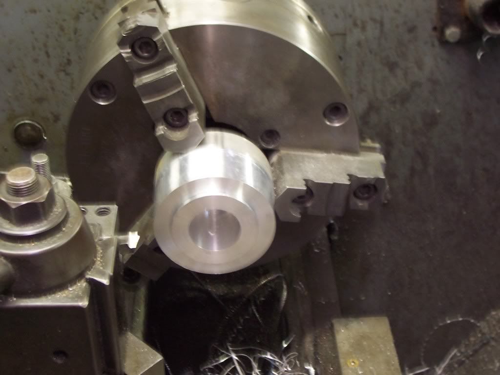
This is a pic of the bearing housing for the flywheel shaft. Here I have turned all the dias leaving stock for finishing. I don't normally finish any dias until the part is roughed to size and I leave .02 to .03 on each dia.

102_1072.jpg


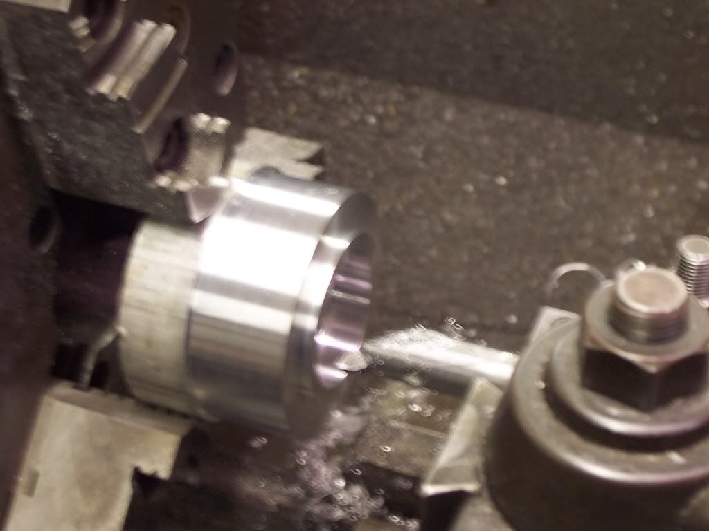
Here I have just finished the bore for the outer race of the bearing on the outboard side of the housing. This boring bar was made from a piece of 4140 and the tool is a broken center drill.

102_1073.jpg


After finishing the face and all the dias to size the part was reversed in the chuck and lightly clamped. A light cut was taken on the face and then checked with mics to see if the part was sitting in the jaws square. The part was tapped until it ran true and then faced to length. My 3 jaw chuck is of the adjustable type so I indicated the bore until I got it running within .0002" TIR. Next I bored the other outer race dia and deburred the part.
 
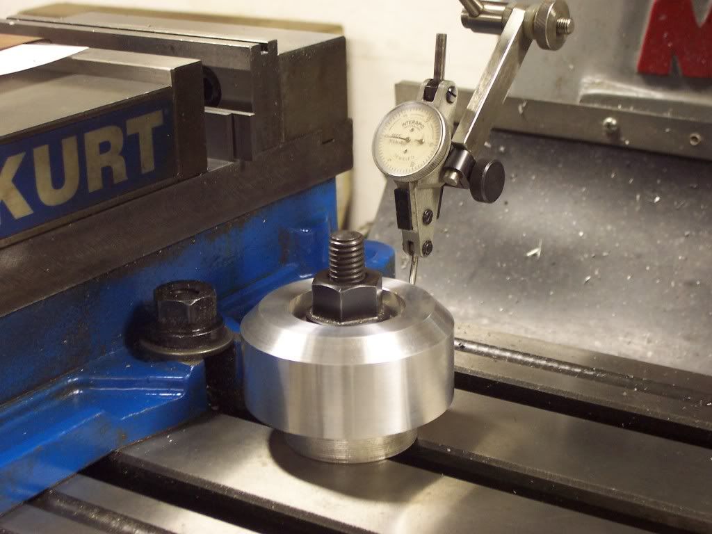
From here I needed to drill some mounting holes in the part. I placed a support piece under the part to give me table clearance and bolted the part through the center to the table of the mill. In this pic I am indicating the OD of the part to find center.

102_1075.jpg


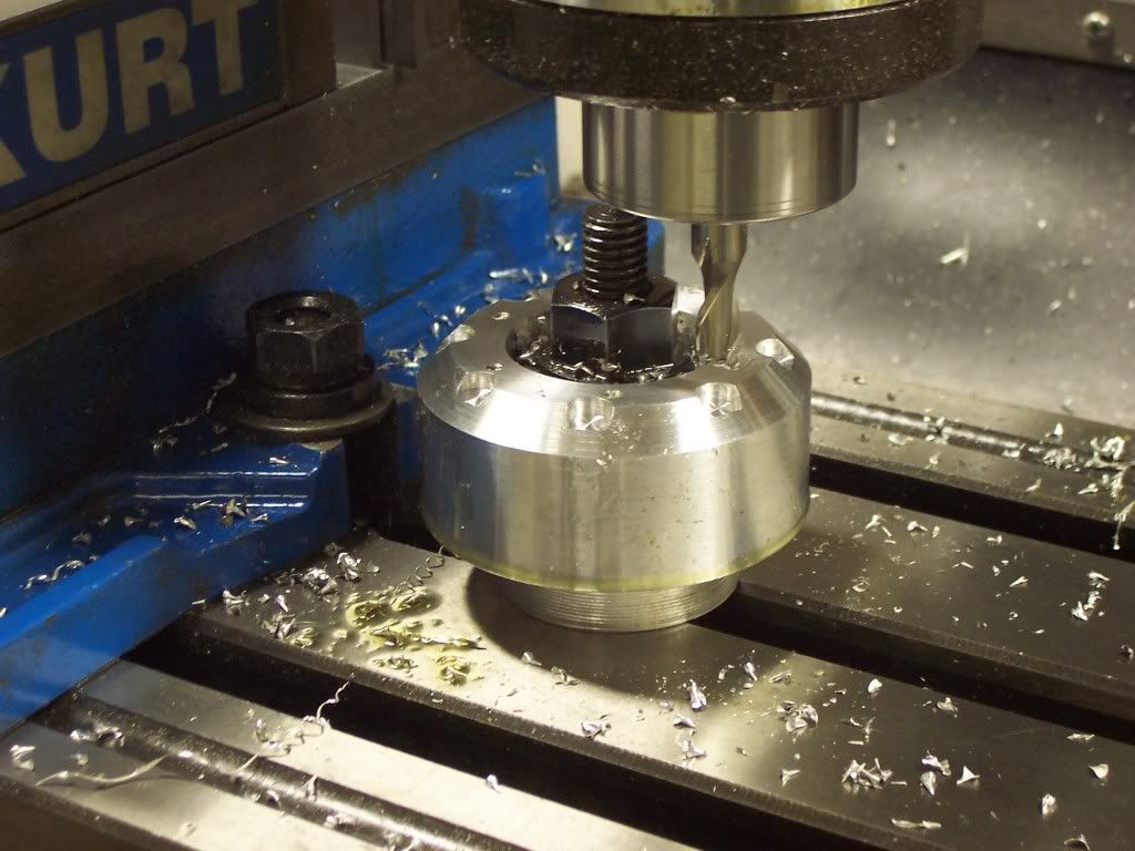
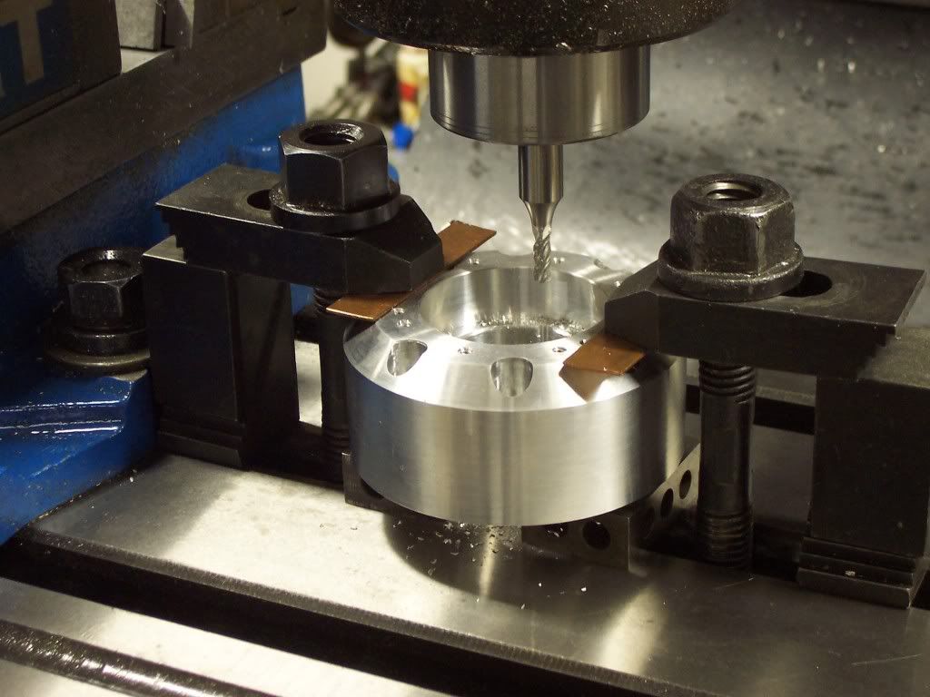
The support will be bolted to the gear housing using 8 10-32 capscrews. The holes for these fall on the intersection of 2 surfaces on the face of the part so I needed to spotface the locations of the holes first with an endmill.


102_1077.jpg


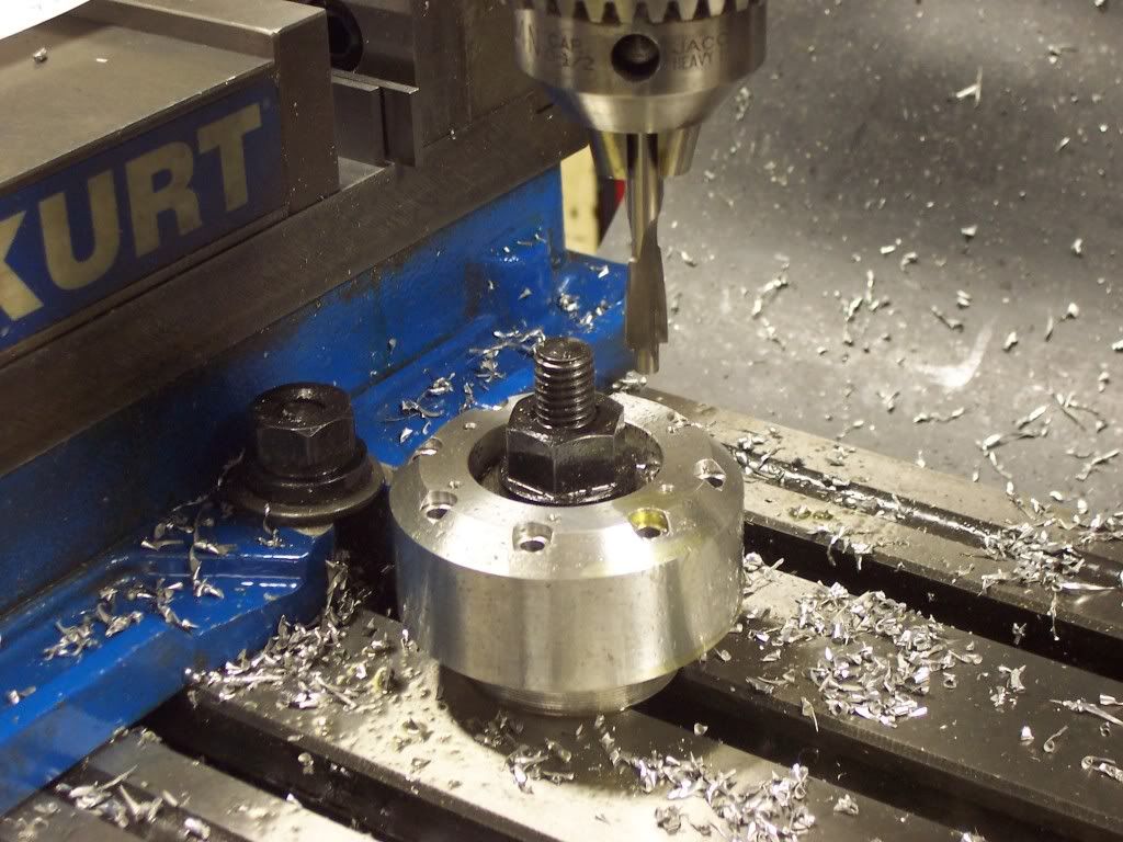
After spotfacing I center drilled and then drilled the clearance holes for the fasteners.

102_1078.jpg
 
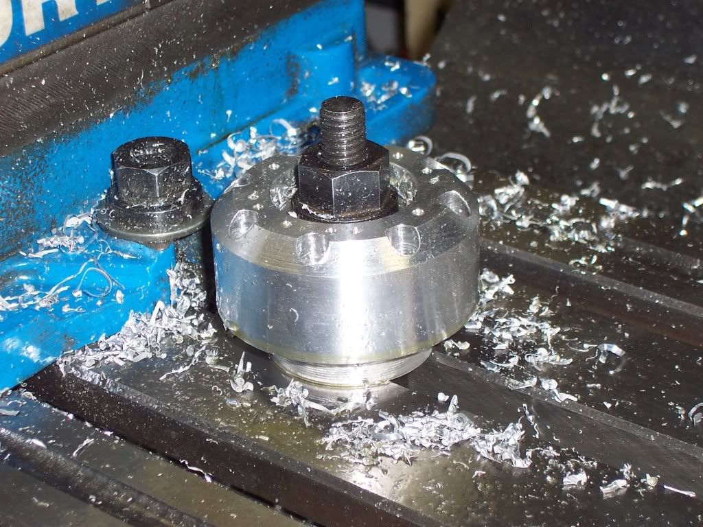
Here we have the counterbores finished.

102_1079.jpg


Now I needed to cut a couple of grooves in the part for a punch just in case I ever have to replace the outer races of the bearings. I had to reclamp the part from the outside so I could access the bore.

102_1080.jpg


The face of the housing got 8 4-40 tapped holes in it for a seal retainer.
 
Hi Dave,

Thanks for the picture of the tool grinder! You did a very nice job on completing the missing parts, must have been fun to do. I truly like these kind of machines, they are very robust and evenbetter most of the times affordable. I do not have space for more machines so I have to stick with what I have. It seems that the only thing missing to convert my Clarcson mill grinder into an OD and surface grinding machine are 2 centers and a variable speed motor. That's not too bad I guess. I would really appreciate to see a detail on your spring tension adjustment, hope I am not nagging now :'(

Regards Jeroen
 
Jeroen, Heres a pic of the spring I used for tension on the center. On the table is the adjuster nut.

102_1081.jpg


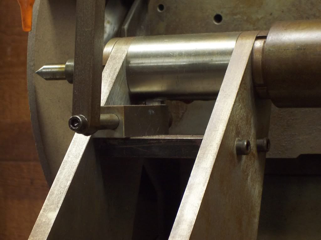
Heres a pic of the lever for retracting the center to install the part on the centers. On the back side of the mounting block that the lever shaft goes through is another lever that goes up into a groove in the tailstock spindle. Move the handle to the right and the center retracts.

102_1082.jpg
 
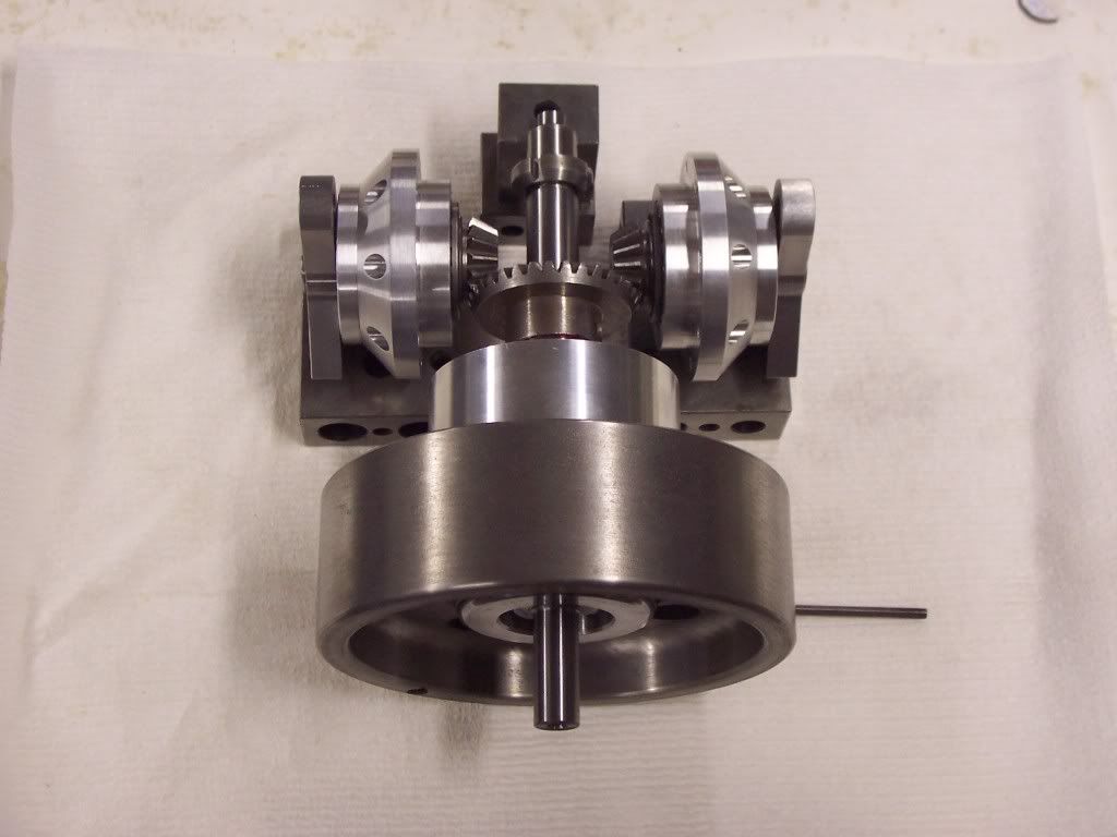
Back to the twin. Heres a pic of the 3 gearshafts with the bearing housings installed. They are placed where they should be. I have to make the spacer for the flywheel bearings yet and grind it to length to get the proper endplay. I also need to make a wrench for the bearing nuts. After that will be the gear housing which will be a weldment.

102_1083.jpg
 
Hi Dave
The quality of your work is amazing, really something to aspire to
:bow: :bow:
Pete
 
Perfect pictures and explanation Dave, thank you so much! If you don't mind I will "steel" this idea to transform my toolgrinder in a OD grinding machine.
Your engine project is going very well, looks good! Keep the progress coming, its a pleasure to follow your building steps!

Regards Jeroen


Thank you Pete, Your support is a big help in keeping me going on this project.

Jeroen, I am happy to help and steal all you want. Thanks for the support on my engine, building these things is always a challenge and its good when others take an interest. If anyone can benefit from the postings then that makes it all worthwhile.

I have a couple Christmas presents to make this week so the postings will probably be a little light until they're finished. One is for my new grandson and another for a good friend. I like to wait until the last minute, actually I don't like to wait until the last minute, it just happens that way. I have to make a stable for the Baby Jesus in my grandson's Nativity scene. I just hope he doesn't grow up thinking his grandpa made the stable that Jesus was born in. Dave
 
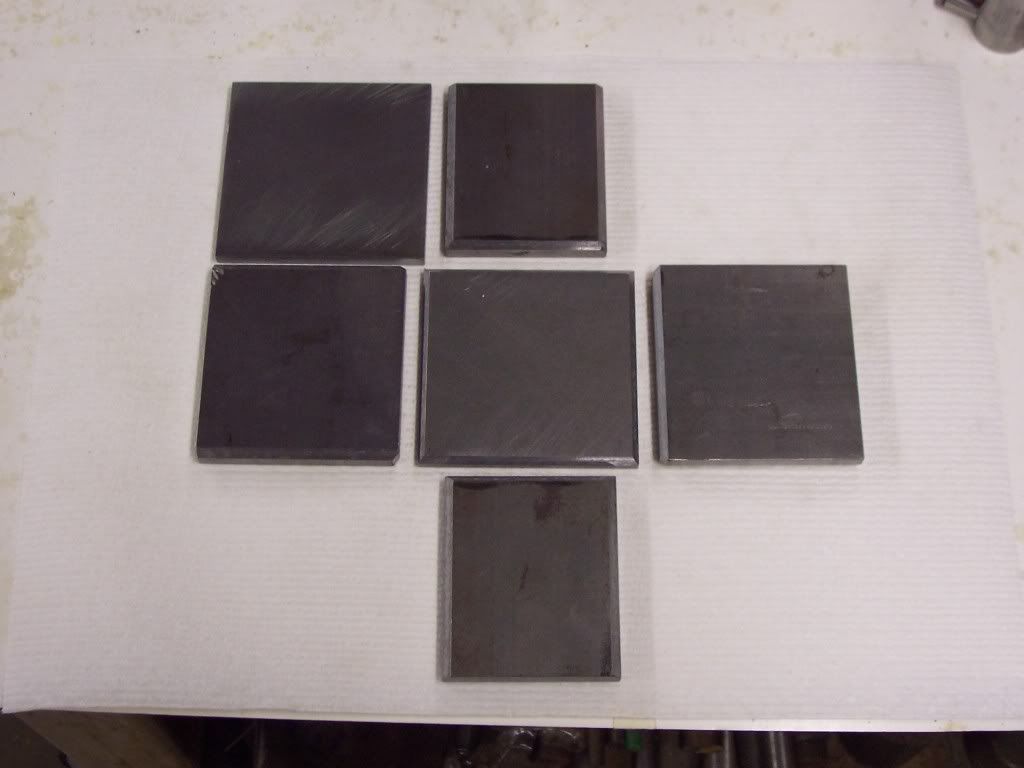
Lets get back at it. I have made the spacer for the flywheel bearings and have adjusted the endplay by grinding this spacer to the proper thickness. I have also made a wrench to tighten the bearing nuts. This pic shows the parts needed for the weldment of the gearcase.

102_1094.jpg


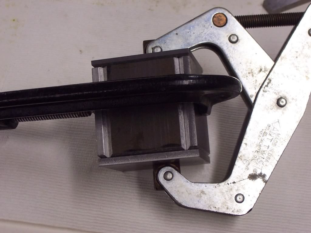
This pic shows the parts clamped and ready to be welded. A generous chamfer was machined on all the joints to help with penetration. I will bewelding with my Lincoln 175 amp Tig welder.

102_1095.jpg


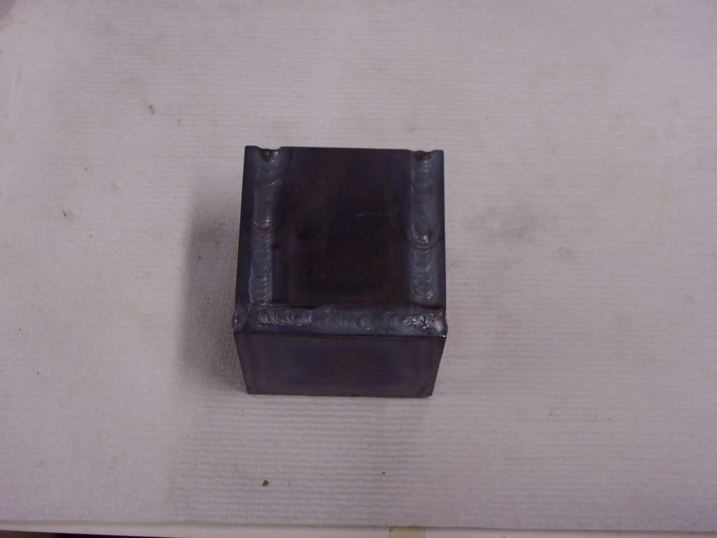
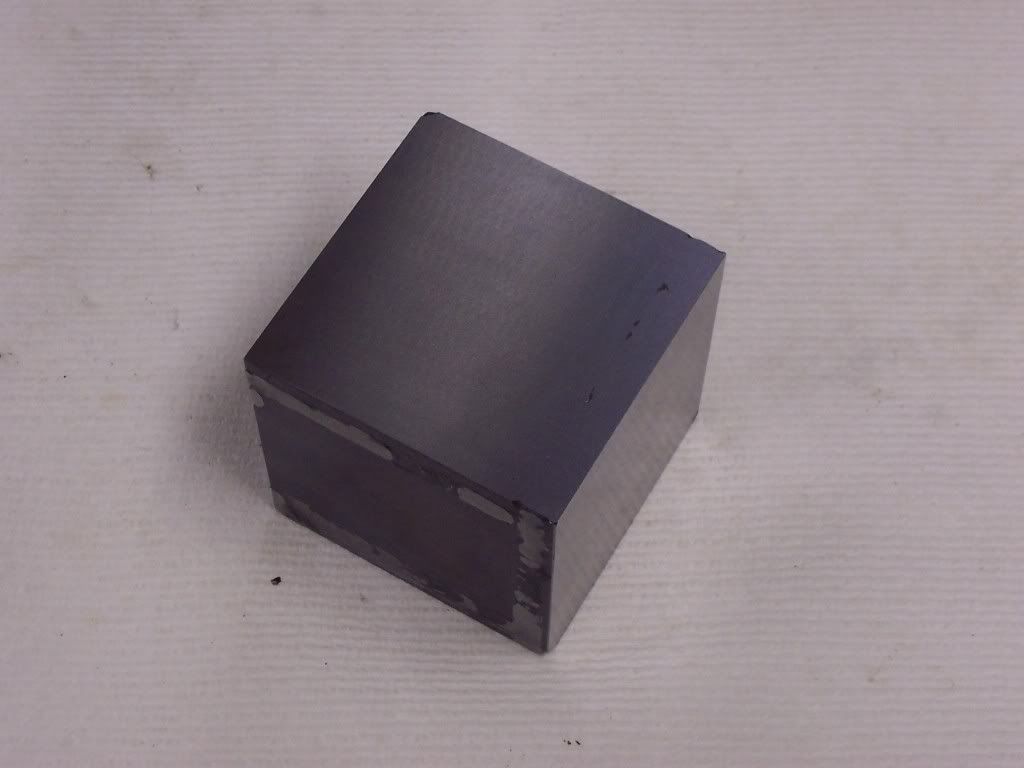
And now we have a welded up block of steel.

102_1097.jpg

 
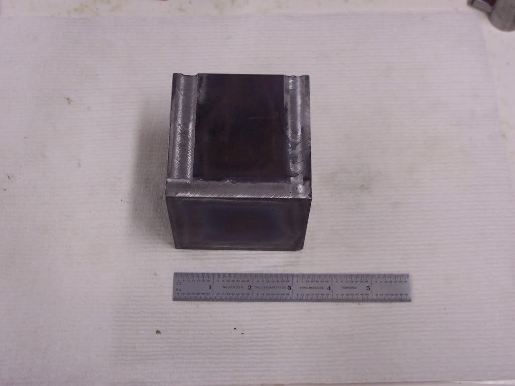
I took the liberty of removing some of the weld that was sticking up off the part by milling.

102_1098.jpg


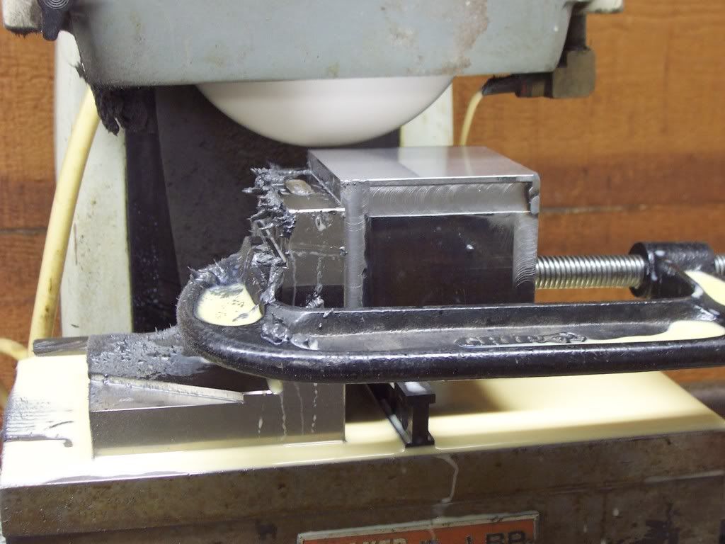
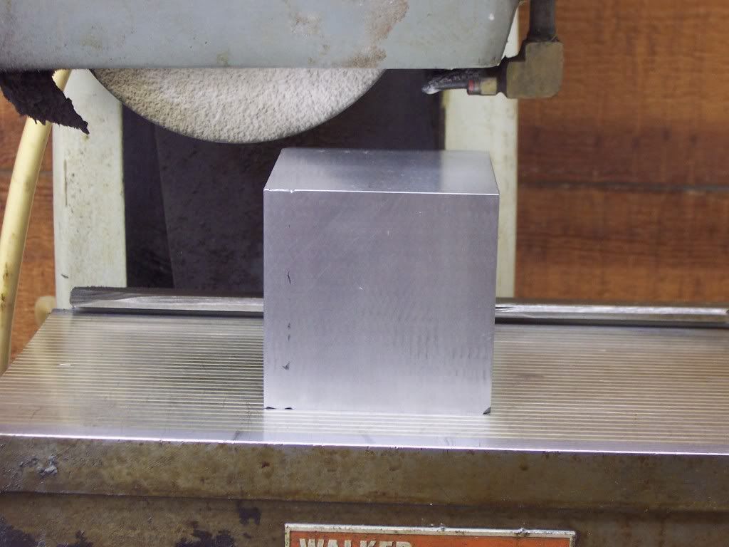
After welding and some mill cleanup the gearcase was deburred and placed on the surface grinder to clean up the top and bottom surfaces. This gave me 2 parallel surfaces to locate the other surfaces from.

102_1100.jpg
 
The gearcase is clamped to my angle plate to grind the 3rd surface. By clamping the bottom surface to the angle plate which is known to be square, we will now have the 3rd side square to the reference side which is the bottom.

102_1099.jpg


After grinding the 3rd side to cleanup it is unclamped and this side is placed down on the chuck and the 4th side is ground to clean up. Now we should have 4 sides ground and square and parallel to each other.

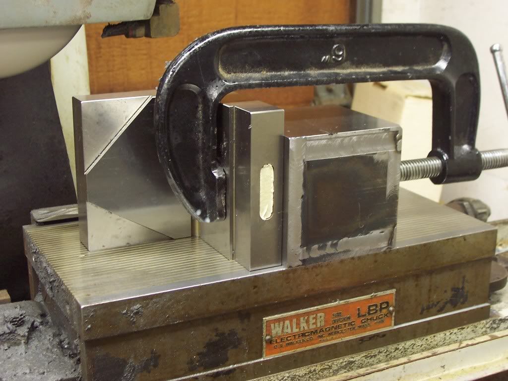
To grind the 5th side we will need to lay the angle plate on its side on the magnetic chuck of the grinder. I will place the bottom face of the gearcase up against the angle plate and the 3rd face I ground down on the chuck. The magnet is energized and then the part is clamped to the angle plate.

102_1101.jpg
 
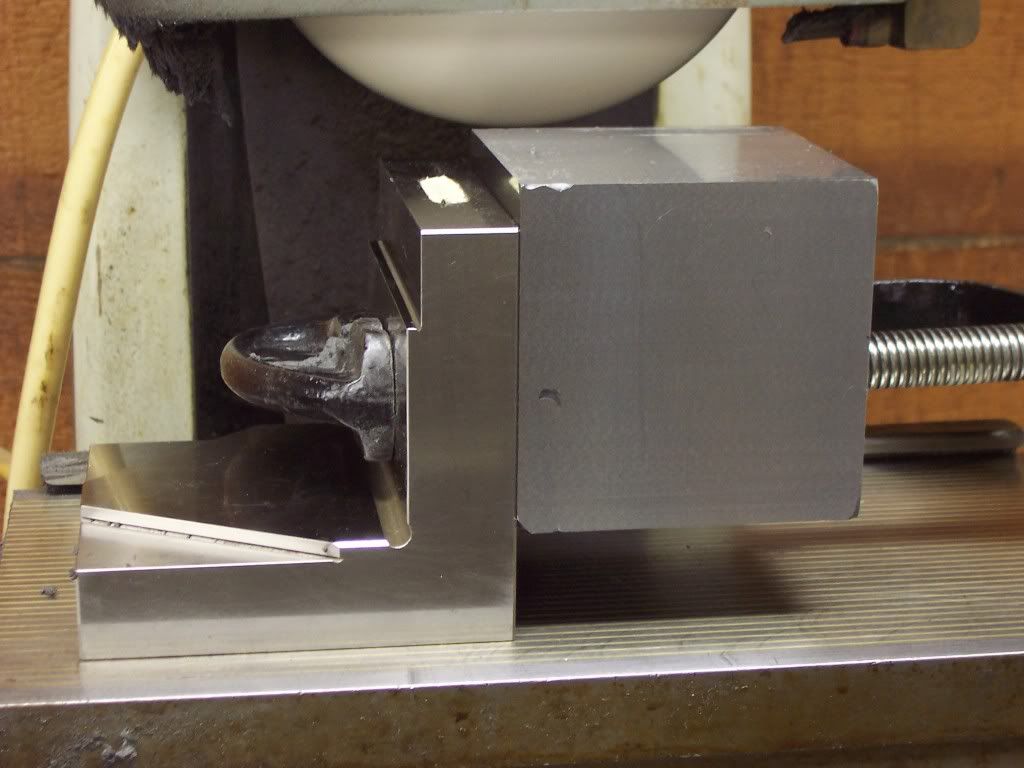
Once the gearcase is clamped to the angle plate the chuck is released and the assembly is rotated on the chuck to allow the 5th side to be ground.

102_1102.jpg


Once the 5th side is cleaned up the gearcase can be unclamped from the angle plate and then placed on the chuck with the 5th side down to be able to grind the 6th side.

102_1103.jpg
 
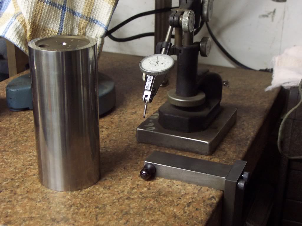
Now we should check to see how square our gearcase really is. I didn't grind any surfaces to dimension yet because I want to see how square the surfaces are to each other. It may need correction so it is best to check before sizing. For this I needed my granite surface plate, a .0001 indicator and base, a cylindrical square, and a gage ball stop.

102_1105.jpg


The indicator is placed above the ball stop and centered with it by eyeball as best that one can. The cylindrical square is pushed up to touch the ball stop and the indicator is adjusted to read zero when touching the square.

102_1106.jpg


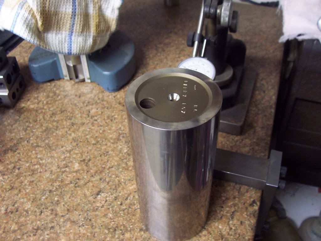
To check to see if the indicator stylus is in the center of the gageball the cylindrical square can be rotated side to side while still touching the gageball. The indicator needle should drop off the same amount on each side when rotated. Whats really neat about using a cylindrical square is you can now check the cylindrical square in many places by rotating the square. Any inaccuracies can be compensated by averaging.


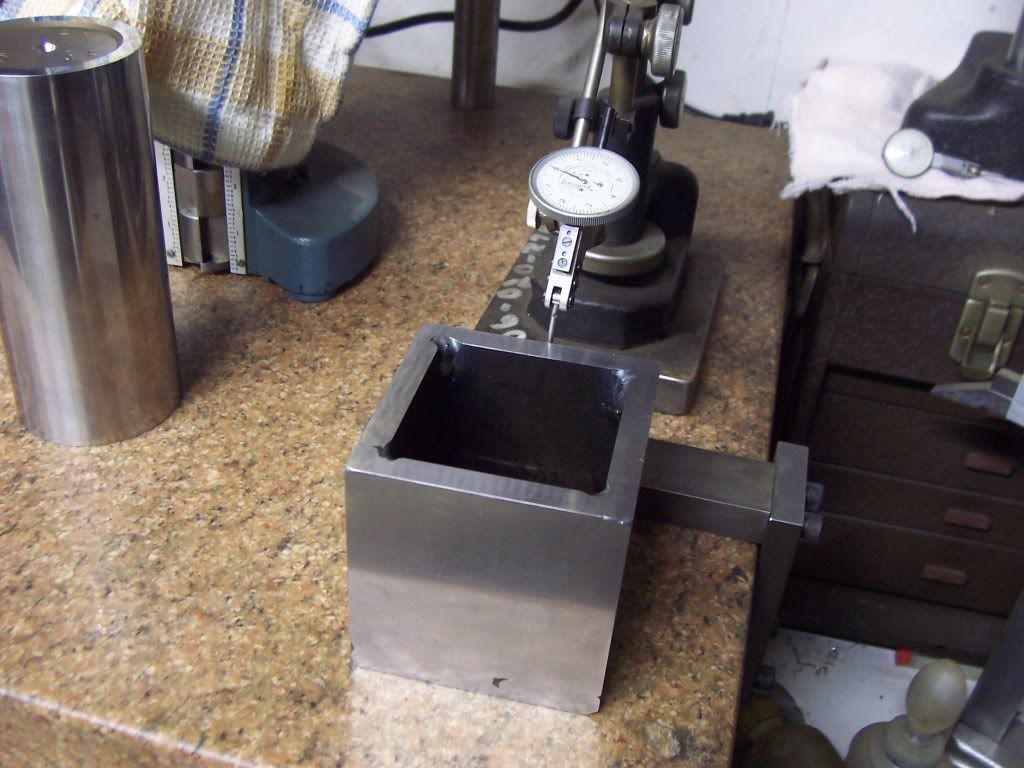
This pic shows the gearcase being checked for squareness.

102_1107.jpg


I found that the worst side was out by less than .0003". Most of the sides were within .00015" and I can live with that. Next I will make a cover for the gearcase and attach it and then I will grind the gearcase to the proper dimensions.
 
Thanks Steve. I spent 6 months in the metrology dept as an apprentice. We were well schooled in how to check things. When we had the opportunity to make an angle plate, as the one you saw in the pics, we would check the squareness as shown. Our goal was less than a .0001" per surface. The trick was to find a journeyman with an angle plate that was good enough to grind from.

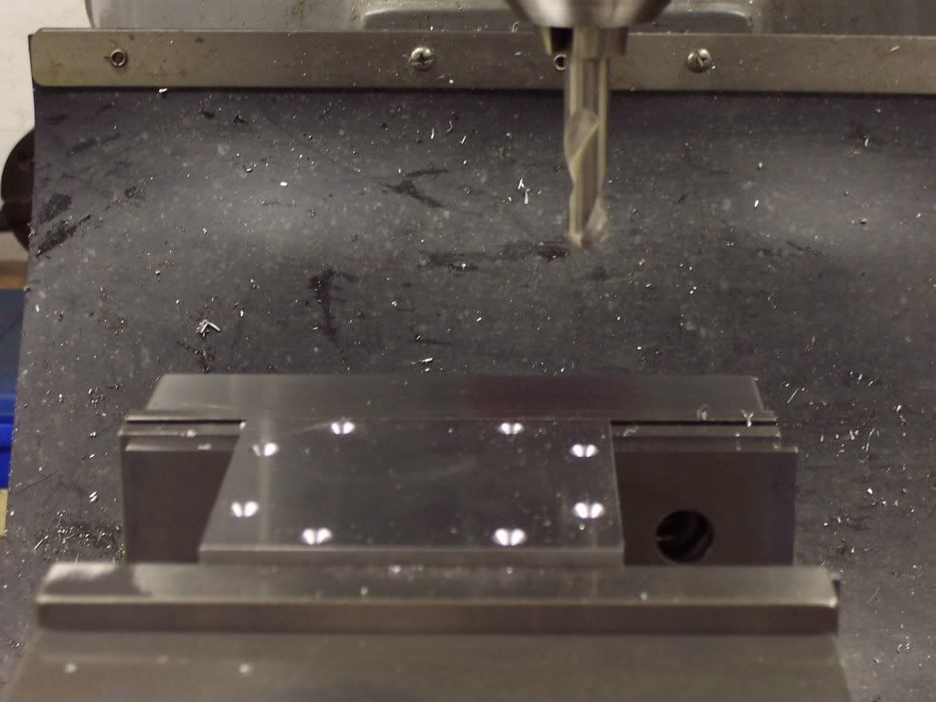
This pic is of the top cover of the gearcase. Here I am spotting the holes with a spotting drill.

102_1108.jpg


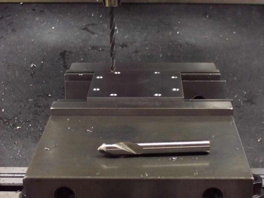
Now we drillthe holes. These holes are clearance for an 8-32 flat head.

102_1109.jpg


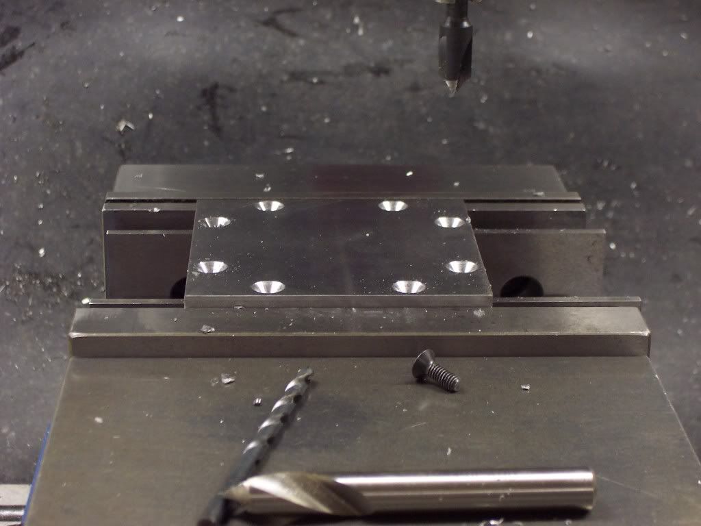
And now for the countersink.
102_1110.jpg


Latest posts

Back
Top