Thanks firebird.--Perhaps you or someome else can tell me--I have read on a post somewhere on this forum of a way to treat brass which will prevent silver solder from sticking to it. Its was something really simple that people used, but I can't remember what it was. I want to build up the side of the rocker arm without getting a ton of silver solder migrating to areas where I don't want it.
You are using an out of date browser. It may not display this or other websites correctly.
You should upgrade or use an alternative browser.
You should upgrade or use an alternative browser.
Brian Builds the Kerzel Hit and Miss I.C.
- Thread starter Brian Rupnow
- Start date

Help Support Home Model Engine Machinist Forum:
This site may earn a commission from merchant affiliate
links, including eBay, Amazon, and others.
mklotz
Well-Known Member
Typewriter "White-out" fluid or a soft lead pencil.
Thanks fellows.---Tel---How is your Kerzel build progressing?
- Joined
- Jan 19, 2010
- Messages
- 1,193
- Reaction score
- 41
Thats a pretty interesting rocker arm Brian. I can see there is a lot of work In that little part. Everything is looking real good, and your coming along very quickly. I cant wait to see all the little "Hit and Miss" parts. Those should be interesting.
Kel
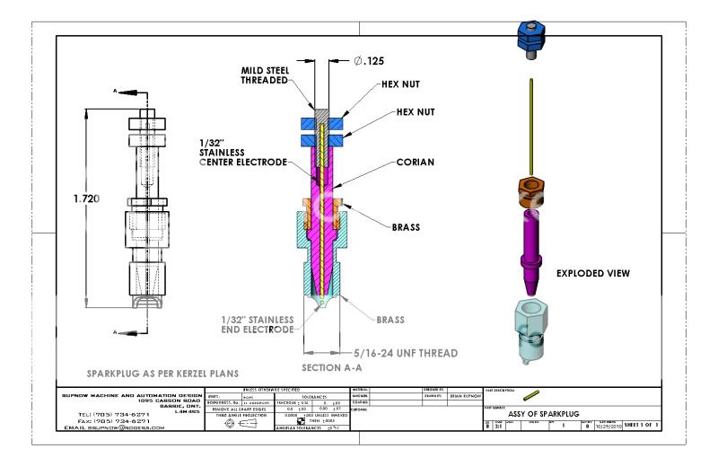
Oh ya, What's the skinny on the two piece spark plug? I cant figure it out.
Kel
Oh ya, What's the skinny on the two piece spark plug? I cant figure it out.
![DreamPlan Home Design and Landscaping Software Free for Windows [PC Download]](https://m.media-amazon.com/images/I/51kvZH2dVLL._SL500_.jpg)
$0.00
DreamPlan Home Design and Landscaping Software Free for Windows [PC Download]
Amazon.com Services LLC

$99.99
AHS Outdoor Wood Boiler Yearly Maintenance Kit with Water Treatment - ProTech 300 & Test Kit
Alternative Heating & Supplies

$171.00
$190.00
Genmitsu CNC 3018-PRO Router Kit GRBL Control 3 Axis Plastic Acrylic PCB PVC Wood Carving Milling Engraving Machine, XYZ Working Area 300x180x45mm
SainSmart Official

$599.00
$649.00
FoxAlien Masuter Pro CNC Router Machine, Upgraded 3-Axis Engraving All-Metal Milling Machine for Wood Acrylic MDF Nylon Carving Cutting
FoxAlien Official

$6.07
$19.95
Sheds & Garages: Building Ideas and Plans for Every Shape of Storage Structure
ZBK Wholesale

$40.02
$49.99
Becker CAD 12 3D - professional CAD software for 2D + 3D design and modelling - for 3 PCs - 100% compatible with AutoCAD
momox Shop

$25.34
$34.99
Peachtree Woodworking Supply Bowl Sander Tool Kit w/Dual Bearing Head & Hardwood Handle, 42 Pieces Wood Sander Set, 2 Hook & Loop Sanding Disc Sandpaper Assortment, 1/4 Mandrel Bowl Sander
Peachtree Woodworking Supply Inc
KCmillin---The sparkplug is being made to plans posted by Kerzel---there is a link to his drawings in my very first post in this thread. I have redone everything in 3D to clarify it for myself, and this is what it looks like. PatJ---I don't like it when it gets this small either. That rocker arm is right on the very ragged end of how small I can work.---Brian

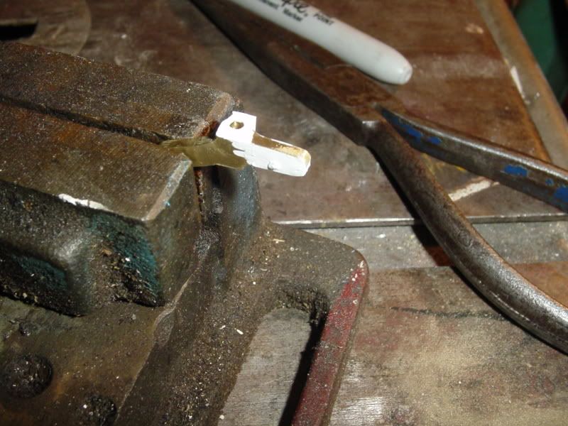
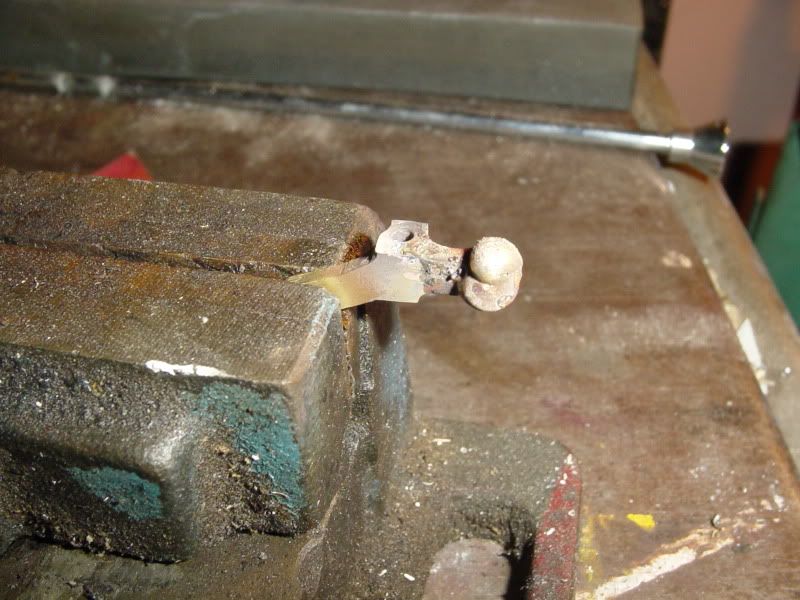
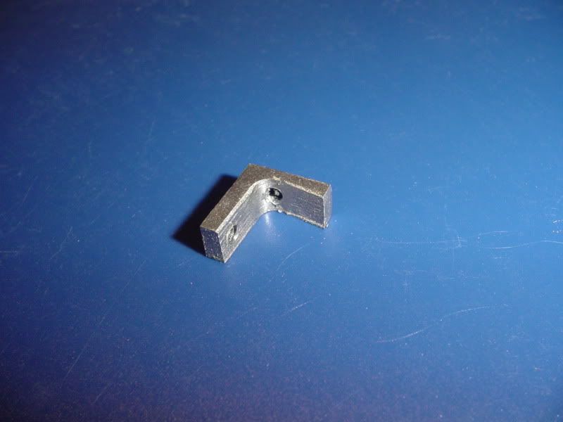
Okay---we gave the "Wite-Out" a try. Actually, it seems to work quite well. If you play the torch flame directly on it, it burns away, but in the areas just outside the torch flame, it seems quite effective in stopping the flow of silver solder. First pic shows the part set up in the vice, with everything coated in Wite out that I didn't want soldered. Pic #2 shows the solder in place, pic #3 shows the finished rocker arm with the excess silver solder filed away.--I think the operation went well. now my rocker arm is cenbtered on the push-rod.
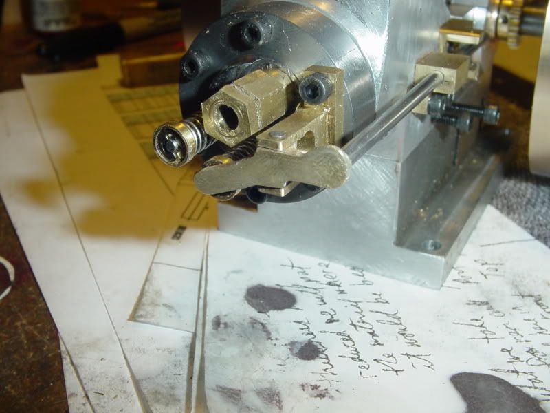


Hows that saying go, Chuck?---"If you can't be good, be innovative!!!" I think it looks better now than it would have if I had machined it correctly in the first place! ;D ;D
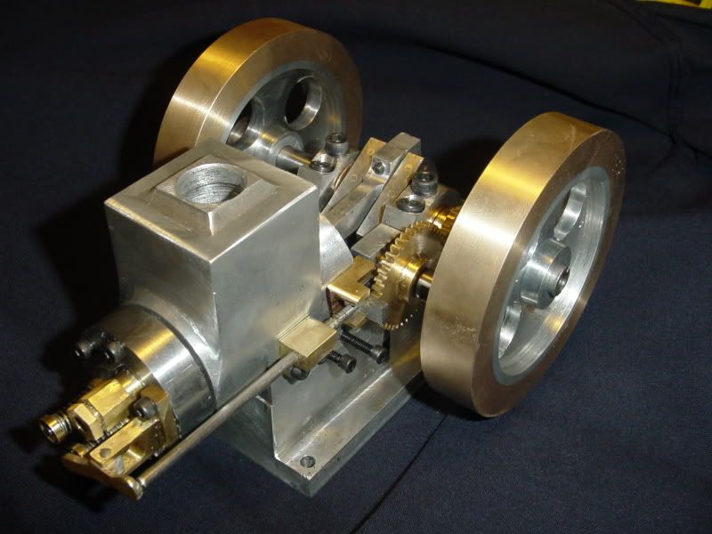
This little engine is taking over my life----Today I started the day by making the "Dog" that the "miss lever" engages with to hold the exhaust valve open. Of course the trick was to get everything to slide properly when its all put together without binding. On assembling all the parts, I found that the hole through the brass bit that the push-rod slides in was about .015" too close to the aluminum frame of the engine, thus putting a severe bind on the pushrod. After determining this by the old "cardbaord cereal box shim under the brass bit" trick, I cut a shim out of some brass .015" shim stock and Loctited it to the underside of the brass guide. While the loctite was setting up, I made the cam shaft stub that the cam gear and cam rotate on. After some esoteric exercises to determine what center to center distance would work with my gears, I drilled a hole in the engine side frame closest to the governor side flywheel and mounted the new camshaft stub, and installed the large cam gear. Then with much filing, sanding, and muttered incantations, I assembled the push-rod and guide and "Dog" and got everything sliding properly.---and that has pretty well eaten my Saturday!!! Wife is sick in bed with a cold and the weather outside is cold, wet, and dreadfull, so I didn't give up too much to work in my comfortable little shop.---And Oh Yes---The hole I drilled for the cam stub seems to be in the right spot. When I turn the engine over by hand, the gears mesh okay. There is one "sticky" spot, but I'm certain it will wear in rather quickly, as the gears are made from brass.


- Joined
- Aug 25, 2007
- Messages
- 3,890
- Reaction score
- 715
Brian Rupnow said:Hows that saying go, Chuck?---"If you can't be good, be innovative!!!" I think it looks better now than it would have if I had machined it correctly in the first place! ;D ;D
The saying that comes to my mind is, "If you can't be handsome, at least be handy!". Think that's from the Red Greene show.
Chuck
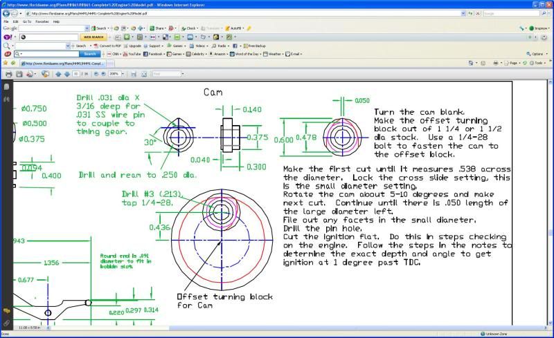
Tomorrow I am going to make the cam. Kerzel made his from brass, and that does not feel quite "right" to me. Brass is soft, and the cam follower bearing running on it will quickly wear a groove---I think. However, the cam rotates on a steel stationary shaft, so if I make it from steel it will have to have a bushing made for it. I have never made a cam using the method Kerzel outlines in his plans, but it seems like a very novel approach. I will make the cam from brass and then see how it holds up. Perhaps it will be fine. If not, I can always make one fro steel and put a bushing in it at a later date, if required.---Brian

tel
Well-Known Member
- Joined
- Feb 8, 2008
- Messages
- 3,293
- Reaction score
- 45
also drilled and tapped the hub on the small gear with four #4-40 threads at 90 degrees.
Lose two of those screws - just put in 2 at 90° - if you install opposing screws to you lose an incredible amount of 'grip' between the gear and shaft. BTW, the second (large) gear should not need any, it should freewheel on its pinion.
SWilliams---Yes, it is an evaporative system. Nick---Yes, its coming along. Tel--In Kerzels plans, the large gear has no setscrews, but is pinned to the cam, and yes, it does freewheel. I didn't know that bit about opposing setscrews not gripping as well---thanks.
Brian Rupnow said:I have never made a cam using the method Kerzel outlines in his plans, but it seems like a very novel approach.

The method has been around sence the late 30's - early 40's. I used it to make the cam for the V4 and it works great. I used a small diamond file to round over the nose of the lobe. If you go with 5 degrees per cut you will be able to polish out the flats very quickly with sand paper. It seems like a pain for one lobe but for 4, 8 ,16 lobes it really works great.
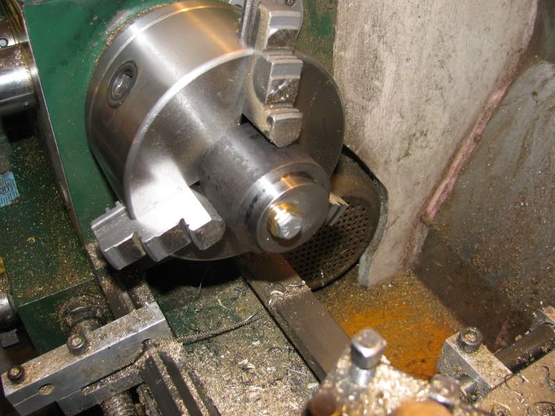
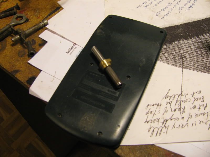
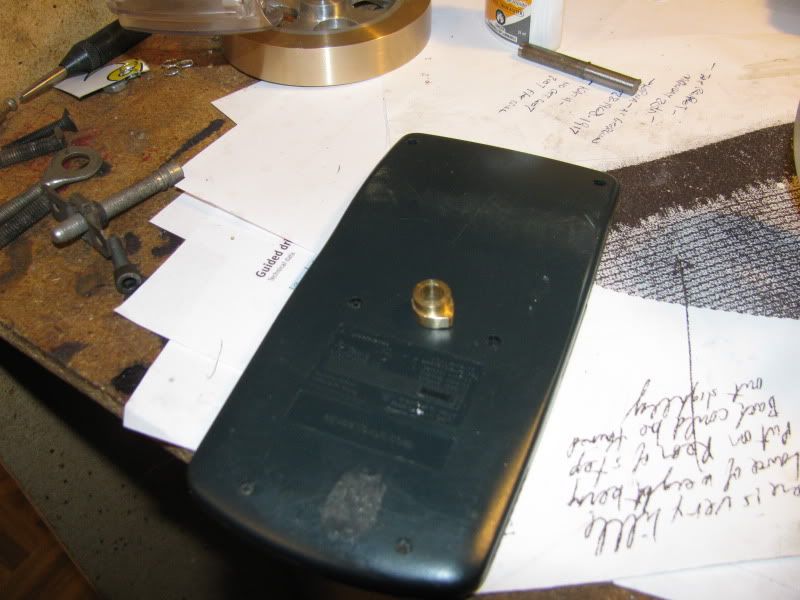
Well, I tried Kerzels method of cam grinding, and like my friend Shania says "That don't impress me much!!!!". For one thing, you can rotate the cam to what you believe to be 5 degrees, but when you go to tighten the bolt up, it grips the cam and rotates it to God knows where. I spent half an hour trying to adjust it to at least give me something that resembled a cam, then said #@%! and took it off the fixture, glued it to a 1/4" arbor, and eyeballed it on my 1" belt sander. I did end up with a cam which I'm sure will work. It only vaguely resembles the dimensions on Kerzels drawing, but it has a total lift of 0.074". Kerzels drawing shows a total lift of .061" I'm sure these little one lung engines don't care all that much, as long as the valve opens and closes at the correct time.


- Joined
- Dec 28, 2008
- Messages
- 1,731
- Reaction score
- 9
Brian. Your project is moving right along.
I don't know if this will help you any, but the few cams I made turned out well using my spin fixture (Spindex clone) to make the cuts, and blended them with a little careful filing. If I remember correctly I used a bevel protractor to check my progress. Can you adjust the lift with the push rod?
-MB
Similar threads
- Replies
- 413
- Views
- 67K
- Replies
- 356
- Views
- 67K


![MeshMagic 3D Free 3D Modeling Software [Download]](https://m.media-amazon.com/images/I/B1U+p8ewjGS._SL500_.png)


