Brian Builds the Kerzel Hit and Miss I.C.

Home Model Engine Machinist Forum

Help Support Home Model Engine Machinist Forum:

This site may earn a commission from merchant affiliate links, including eBay, Amazon, and others.
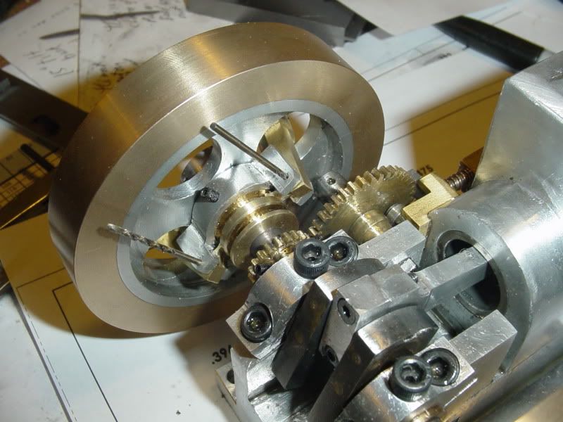
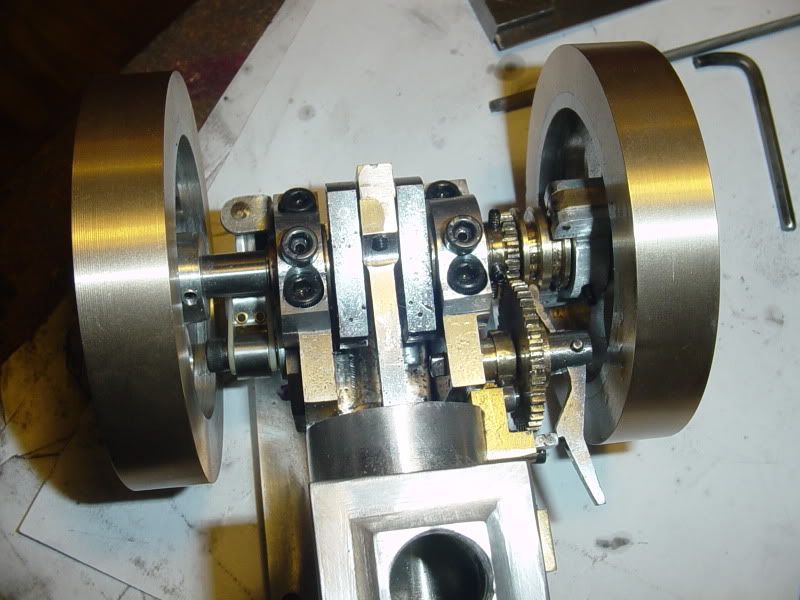
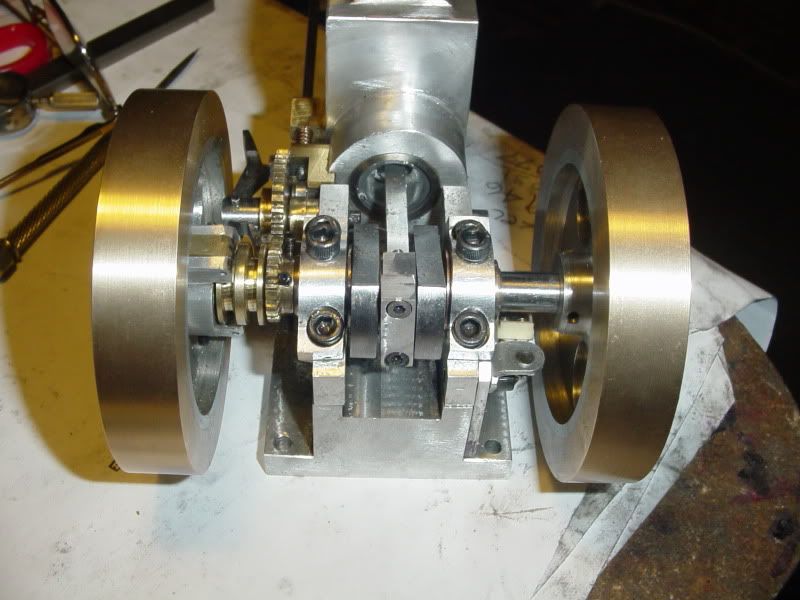
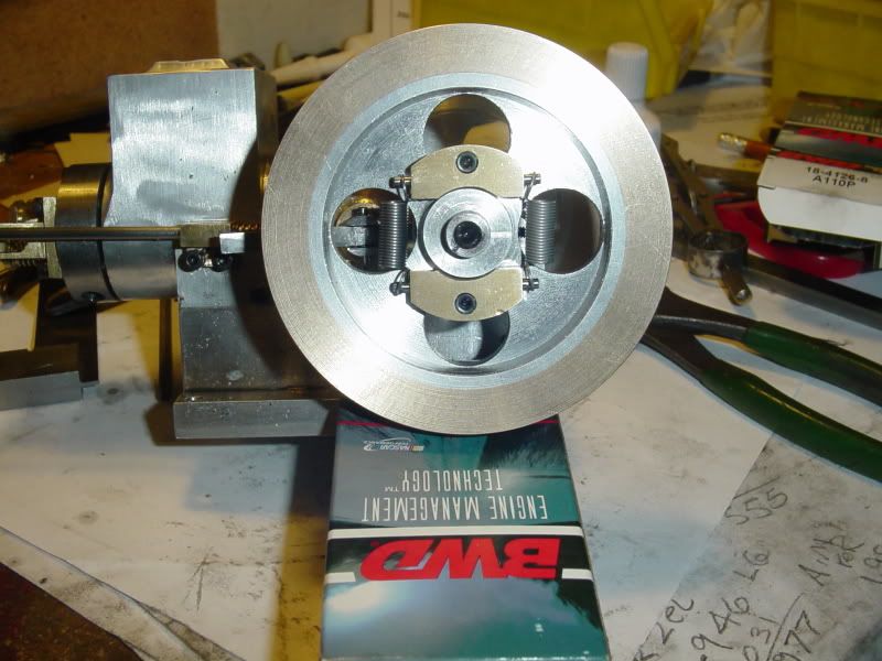
These pictures show the governor weights from both sides of the flywheel in "high speed" mode, where high engine RPM has caused them to fly out as far as they can from the center of the crankshaft, and consequently moved the spool. On this model engine, the spools total travel is only about 0.080".
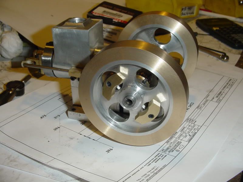
governoronengine001.jpg

governoronengine002.jpg
 
Looks good brian, these are the intricate little parts that I fear most I think. I can't quite see how it props the exhaust valve open on this design but I'm sure all will be revealed shortly.

Nick
 
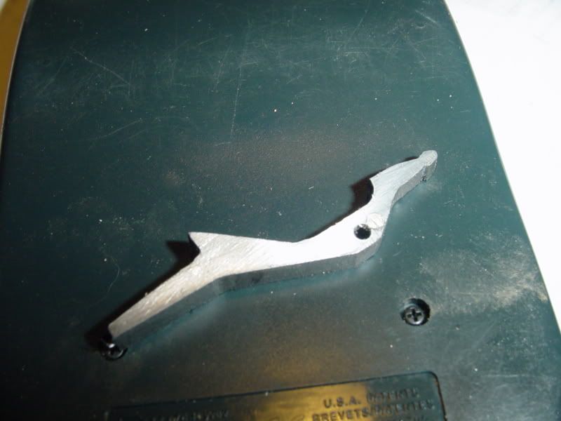
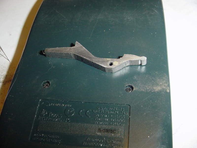
And here we have the govenor arm---Hereafter to be dubbed the "Kerzel Lever". An ugly looking damn thing, and even as ugly as it is I managed to drill the pivot hole in the wrong place. I filled the hole with silver solder and carried on. This is what rides in the other slot in the spool and pivots to hold the exhaust valve open. I will post a picture of it assembled---Brian
GOVERNORARM002.jpg

GOVERNORARM001.jpg
 
Brian Rupnow said:
An ugly looking damn thing, and even as ugly as it is I managed to drill the pivot hole in the wrong place.

I thought it was just me, but I had similar thoughts when I looked the plans over.

It's got more angles than a con artist! :big:

-MB
 
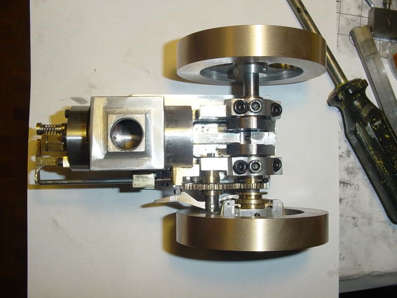
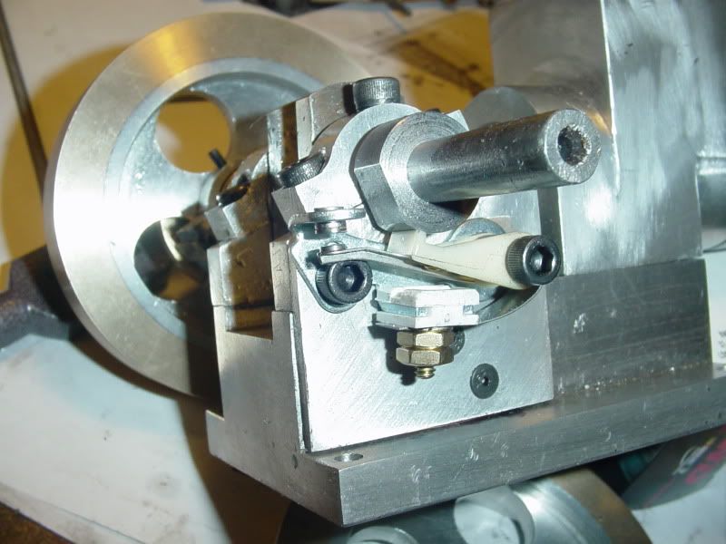
Well, after a day of assembling, disassembling, filing, grinding, cussing, and reassembling I have the Kerzel arm in place, doing its thing. Although the end closest to the cylinder head is much as Kerzel designed it, there were serious interferance issues on the end nearest the crankshaft. However, after spending all of today I have it working the way its supposed to. In the picture, the weights are in the "out" position, the Kerzel lever is tipped in at the cylinder head end and is caught under the cam follower bracket, thus preventing it from following the cam, and holding the exhaust valve open. I don't have the return springs on the weights yet, but by gently squeezing them together with finger pressure while rotating the flywheel by hand, they do force the spool in towards the engine centerline, thus tipping the Kerzel arm the other way, and this lets the cam follower follow the cam (under pressure from the spring you see on the pushrod), thus allowing the valve to close. Whew---Its almost as much work to describe it as there was involved in making it!!!
kerzelarminplace-2002.jpg
 
Any explanation what the extra length sticking out at an angle to the left of the push rod stop is for? I think the whole thing would look a lot better without it...

Chuck
 
Chuck---I wondered that myself, but I think I figured it out. It looks like something that can be activated/de-activated with your finger while the engine is running.
 
Thanks ever so much to Ken in Winnipeg, who sent me a nice peice of Corian. I could have swore that he said it was going to be blue, but its a nice porcelain white.--Might actually look like a real sparkplug!!! Can anybody suggest lathe RPM and cutting tool type for this stuff? Diameter of sparkplug will be about 3/8".---Brian
 
Actually I do have some speckled blue stuff, but it didn't seem appropriate some how.
 
It is sometimes helpful to override the governor while adjusting mixture.
Gail in NM
 
GailInNM said:
It is sometimes helpful to override the governor while adjusting mixture.
Gail in NM

Hmmm. I've tried overriding the governor on my hit n miss using my finger and it was altogether scary. I guess you could maybe speed up or slow down the engine by pushing or pulling on the lever.

Chuck
 
I was wondering exactly the same thing! Guess it makes sense, you're working with the springs so shouldn't be too hard to hold it back, the governor should be run with a wide open throttle shouldn't it, will this engine have a throttle brian, guess there's not much point?

Nick
 
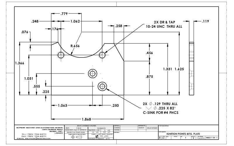
I made up a small aluminum adapter plate which allows me to install a set of automotive ignition points on the side of the engine opposite from the governor flywheel. The points are for a Chrysler product---not sure what year, but they are distributed by BWD Automotive in Long Island N.Y. I bought them at PartSource. Numbers on the box are 18-4126-8 A110P. these are the same ignition points I used on my Webster I.C. engine. This is the adapter plate, but it will not work on Kerzels engine as he designed it. I redesigned the base to be much deeper than Kerzels, so I wouldn't have to mount the engine on a wooden block like Kerzel did to let the flywheels clear.
IGNITIONPOINTSMTGPLATE.jpg
 
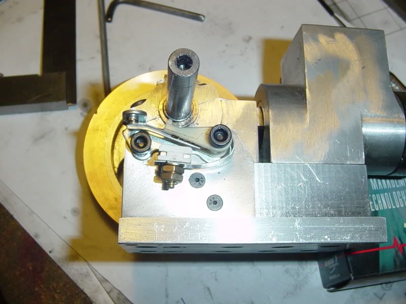
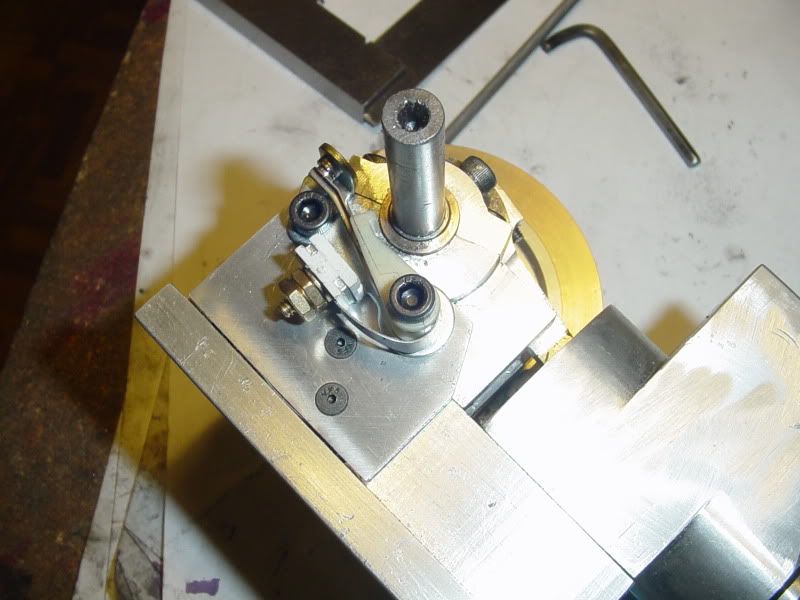
Here are a couple of shots of the adapter plate and the ignition points mounted on the engine. I will build the cam tomorrow---Its the same as the cam on the Webster, only with a 3/8" bore instead of the original 5/16".

ignitionpoints001.jpg

ignitionpoints002.jpg
 
I had to stop at Brafasco, my nuts and bolts store this afternoon to pick up the flathead capscrews that hold that adapter plate to the engine. While I was there, I noticed a whole bin full of springs that looked like they might work as governor springs on my engine. I grabbed a pair, and they are the correct length, but they may be too heavy---This is the kind of thing I can never tell about untill I get the engine running. If it goes into "miss" mode, I know the springs were right. If it doesn't, then they were too heavy.---Precise engineering, eh!!! I drove down to Brampton this morning and quoted a design job, and got a confirmation call giving me the go ahead at suppertime. Nice 4 week contract, retrofit design on a big rotary table machine making automotive parts.---I start it on Monday morning. Progress on the Kerzel engine may slow down dramatically. --I took a good look at the assembly drawing this evening, and it looks like the only things remaining are to finish the sparkplug and build a carburetor.
governorsprings001.jpg
 
Just about there... Do you have a part number for those points?

Chuck
 
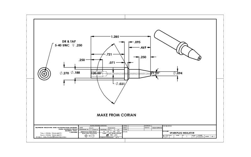
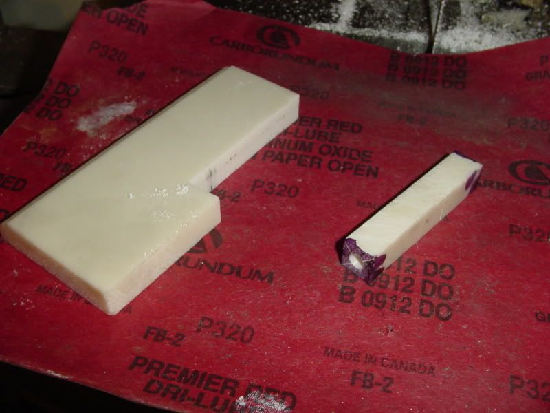
This is the saga of the $300+ sparkplug!!!!!!!!!!!! First off, here is what the insulator is supposed to look like, and the first step--Corian is cut into a peice 1/2" square x 2 1/4" , and the ends conterbored to accept lathe centers..
SPARKPLUGINSULATOR.jpg

CORIANSPARKPLUG-1001.jpg
 

Latest posts

Back
Top