You are using an out of date browser. It may not display this or other websites correctly.
You should upgrade or use an alternative browser.
You should upgrade or use an alternative browser.
Brian Builds the Kerzel Hit and Miss I.C.
- Thread starter Brian Rupnow
- Start date

Help Support Home Model Engine Machinist Forum:
This site may earn a commission from merchant affiliate
links, including eBay, Amazon, and others.
Chuck---It took me literally 5 minutes to think them up and draw them. It took the entire day to build them. This included time to go upstairs and change into clean underwear after that 9" chunck of bronze came flying out of my chuck at 920 RPM and went rickoshetting around my 7 foot square machine shop. I don't have a live tube center so I was trying to take VERY light cuts from the stuck out end to get the face squared up. DOESN'T WORK---Won't do that again!!!!
- Joined
- Aug 25, 2007
- Messages
- 3,890
- Reaction score
- 715
Yikes! You might have to fabricate a steady rest to hold the outboard end of such things. Or, as you say, a live bull center would work and they aren't very expensive.
(Hope you didn't booger up the bronze too much!)
Chuck
(Hope you didn't booger up the bronze too much!)
Chuck
Chuck---I have a beautifull new steady rest which I have never used. I did actually pull it out of the cupboard and adjust it to its greatest diameter, and found that it was still too small to fit over that peice of bronze. It didn't bugger up the bronze at all----one end had a counterbore about 1/2" deep that was no good to me, so I had the jaws INSIDE the counterbored end holding pressure on the part in expansion. I never stand in front of what I am machining. I always stand off to one side towards the tailstock. Its a damn good thing, or I would have a large nasty hole through myself. You're right--those bull centers cost about $80 and you only have to use them once every 5 years.
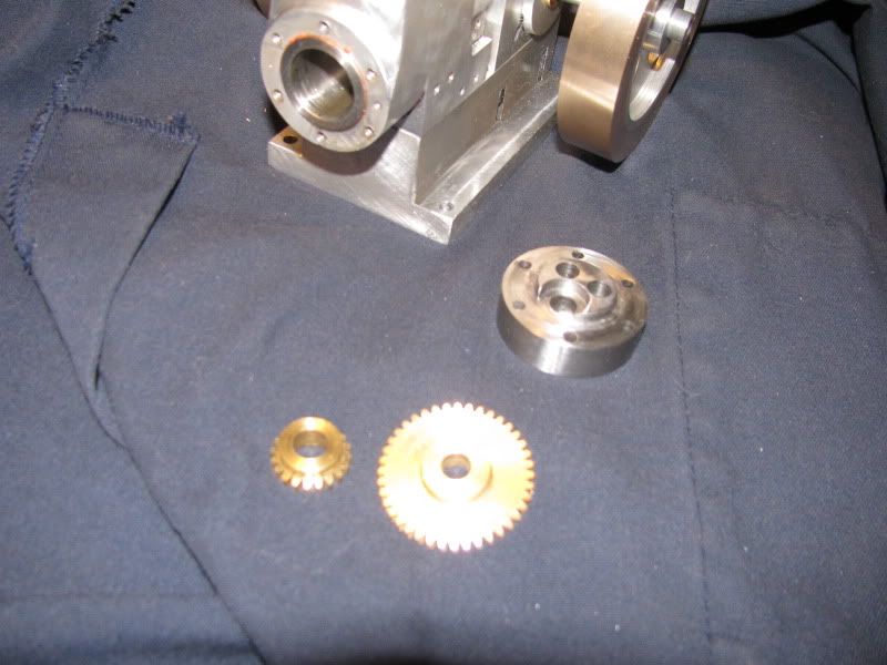
Great news!!! Way back about 3 weeks ago, when I started this engine, a kind gentleman from Perrysburg Ohio emailed me and volunteered to make the timing gears for me. This was indeed a great kindness, as I don't have a set of gear cutting tooling and would have had to buy either the tooling or the gears. He made them, sent them off, and they dissapeared into the black hole which resides at the center of the postal service universe. I had given up on ever receiving the gears, and he had even volunteered to make me a second set of gears to replace the first set. The original pair he sent arrived today, and they are beautifull. Of course, he machined the bore on the small gear to Kerzels drawing, which is wrong, but I can correct that. Thank you, Jim!!!


$45.99
Sunnytech Mini Hot Air Stirling Engine Motor Model Educational Toy Kits Electricity HA001
stirlingtechonline
![DreamPlan Home Design and Landscaping Software Free for Windows [PC Download]](https://m.media-amazon.com/images/I/51kvZH2dVLL._SL500_.jpg)
$0.00
DreamPlan Home Design and Landscaping Software Free for Windows [PC Download]
Amazon.com Services LLC

$599.00
$649.00
FoxAlien Masuter Pro CNC Router Machine, Upgraded 3-Axis Engraving All-Metal Milling Machine for Wood Acrylic MDF Nylon Carving Cutting
FoxAlien Official

$25.34
$34.99
Peachtree Woodworking Supply Bowl Sander Tool Kit w/Dual Bearing Head & Hardwood Handle, 42 Pieces Wood Sander Set, 2 Hook & Loop Sanding Disc Sandpaper Assortment, 1/4 Mandrel Bowl Sander
Peachtree Woodworking Supply Inc

$40.02
$49.99
Becker CAD 12 3D - professional CAD software for 2D + 3D design and modelling - for 3 PCs - 100% compatible with AutoCAD
momox Shop

$99.99
AHS Outdoor Wood Boiler Yearly Maintenance Kit with Water Treatment - ProTech 300 & Test Kit
Alternative Heating & Supplies

$171.00
$190.00
Genmitsu CNC 3018-PRO Router Kit GRBL Control 3 Axis Plastic Acrylic PCB PVC Wood Carving Milling Engraving Machine, XYZ Working Area 300x180x45mm
SainSmart Official
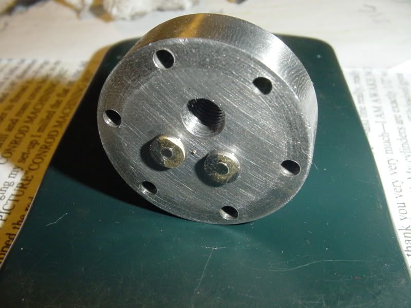
This afternoon we have a couple of brass valve guides, machined and loctited into place. They will be reamed to size tomorrow, in place, and the valve seats cut in the head at the same time to maintain concentricity. These were easier to build than they were to photograph. I am not a very good photographer, and it took my 3 tries with 2 different digital cameras to get this rather lousy picture.
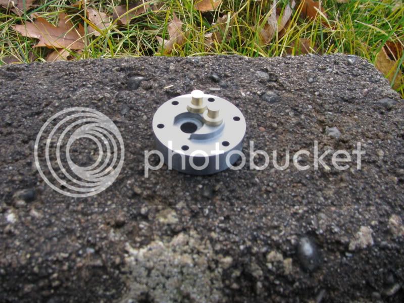

......... I am not a very good photographer, and it took my 3 tries with 2 different digital cameras to get this rather lousy picture.
Good thing you did not quit your other job then Rof} Rof} Rof}
sorry Brian, I had to. :hDe:
Looking good so far.
BC1
Jim
Question----The valve guide has to be drilled and reamed "in place" in the cylinder head, and the valve seat (which in this case is machined into the cylinder head) has to be machined at the same time to guarantee concentricity. Okay---not a big problem---I set the cylinder head up in my mill upside down, indicate off the reamed hole for each guide to find the center, and then drill and ream the guide. But what do I then use to cut a 45 degree taper for the valve seat in the cylinder head? All I can think of at the moment is a 90 degree metric countersink tool. And no, I don't want to make a special one time only peice of tooling. Any suggestions, or do I go with the metric countersink?
Maryak
Well-Known Member
- Joined
- Sep 12, 2008
- Messages
- 4,990
- Reaction score
- 77
Brian,
The countersink sounds OK to me, just be wary of chatter. The other easy option is to grind an ordinary jobbing drill to 90o included angle using the inside corner of an engineers square to get the angle.
Hope this helps.
Best Regards
Bob
The countersink sounds OK to me, just be wary of chatter. The other easy option is to grind an ordinary jobbing drill to 90o included angle using the inside corner of an engineers square to get the angle.
Hope this helps.
Best Regards
Bob
doc1955
Gone
- Joined
- Aug 26, 2009
- Messages
- 1,261
- Reaction score
- 168
A metric counter sink tool only refers to the diameter as metric the angle is still the same as ant other. The counter sink tool you have is it a single flute or multiple flute? I have found the single flute c/sink tools have less chance of chatter.
Brain your build is looking good!!!
I know what you mean with the camera I'm not to good with the beasts either and it's pure luck if I get a good shot.
Brain your build is looking good!!!
I know what you mean with the camera I'm not to good with the beasts either and it's pure luck if I get a good shot.
- Joined
- Aug 25, 2007
- Messages
- 3,890
- Reaction score
- 715
Brian, I've used a 45 degree milling cutter which should work the same as a 90 degree counter sink. You could also mount the head in your 4-jaw chuck with the valve seat side facing out. Then use a drill and reamer in the tailstock to drill the hole for the valve stem. Finally, cut the 45 degree valve seat with a tool bit on your compound set at 45 degrees.
Chuck
Chuck
Chuck---I laid in bed with my head on fire for 4 hours last night, and came to the same conclusion as you.--The dreaded 4 jaw chuck in the lathe approach. Actually, that might not be so bad, because I do have a reamed hole to line up on. If I put a 3/16" stub shaft in the tailstock chuck, and adjust the cylinder head in the 4 jaw untill the stub will slide smoothly into the hole in the cylinder that I want to cut the valve seat on, that should do it.---Thanks
doc1955 said:A metric counter sink tool only refers to the diameter as metric the angle is still the same as ant other. The counter sink tool you have is it a single flute or multiple flute? I have found the single flute c/sink tools have less chance of chatter.
Brain your build is looking good!!!
I know what you mean with the camera I'm not to good with the beasts either and it's pure luck if I get a good shot.
British Imperial countersinks are 82 degrees. Metric countersinks are 90 degrees.
doc1955
Gone
- Joined
- Aug 26, 2009
- Messages
- 1,261
- Reaction score
- 168
In the US a 82 degree c sink is used mostly for flush head cap screws 82 and 90 both used here. I guess I'm not sure why it would be any different in British imperial. So if you lay a square over a metric 90 degree c sink it isn't 90 degrees that would be odd I'm not saying you are wrong because I don't work with British imperial I'm just trying to understand why that would be.
Have you ever wondered to yourself "Gee---I wonder what a crude, ugly, lash-up looks like?" Well, wonder no longer Bunky---This is what it looks like!!! As my old electrical engineer used to say "TEFC"--Totally Effective, Fantastically Crude. However, it did work great for putting the 0.020 anular groove at the end of the valve stems for the retaining circlips. I decided that before I part the valves off from the main chunk of 5/16" mild steel round bar they are a part of, I should put the groove in. Those 3/32" valve stems are uber fragile. After twice trying to turn the 5/16" stock down to 3/32" and twice having it twist off, I machined the valve head only on each end, then drilled and reamed for a peice of 3/32" cold rolled in each end---then cut half way through the 5/16 round bar just 1/32" above the head of the valve and silver soldered thru the sawcut. my goal is to end up with two valves with "handles" about 2" long on each big end, so that I have something to hold onto when I lap the valves into the cylinder head valve seats (which I haven't machined yet.) After I have attained an air tight seal on each valve, I will cut the handles off and be left with a normal looking valve.
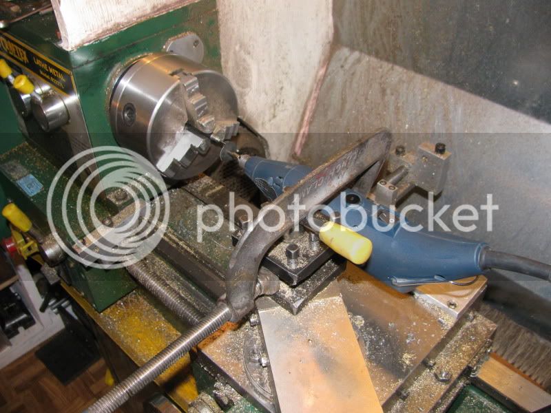
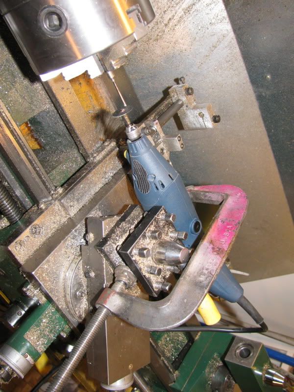


Like this---
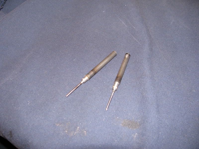

The valve seat cutting adventure was a success!!! I did use the 4 jaw chuck on the lathe, and it went very well. I put a 3/16 peice of cold rolled in the tailstock chuck, and used it as an alignment spud to get the cylinder head where it needed to be, then VERY carefully brought the individual jaws up untill they just touched the cylinder head, then tightened them all incrementally. When it was plain that I had not induced a bind on the alignment spud, I drilled and reamed the brass bushing in place, and then without moving any of my set up I set the compound rest over at 45 degrees and chamfered the individual valve seats. The second one was harder to get a perfect no bind alignment on than the first, but after 2 or 3 trys it too came out very well. Visually, the chamfers are very concentric. The picture shows the two valves in place (with "handles" still attached). I will lap them tomorrow by hand with a fine valve grinding compound, then cut the "handles" off.
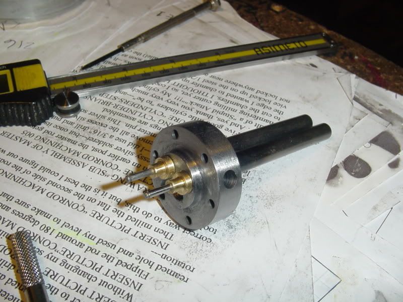
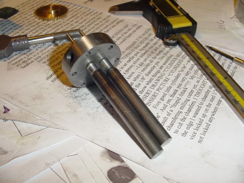


We have functioning, non leaking valves.-(As verified by "Put your mouth over the cylinder exhaust and intake ports one at a time and blow till you start to feel dizzy!!!"--If no air is escaping unless you manually push the valve stem down, its okay.) The hardest part of the whole thing was A--Finding a place that sold retaining clips this small, and B--Trying to hang on to the darn things to install them!!!
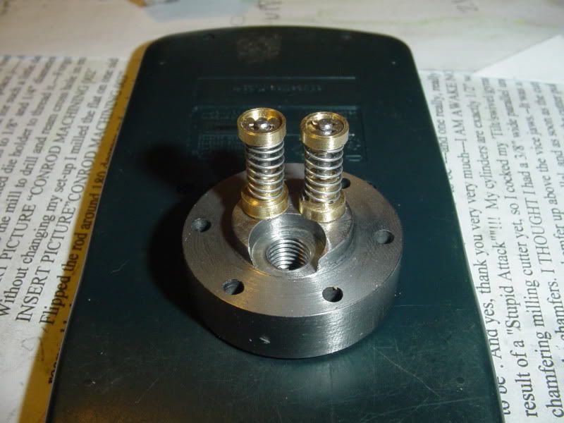


Gloom, despair, and agony on me---With everything assembled and gasketed, I have no compression. In order to find out WHY not, I machined an adapter to screw into the sparkplug hole and put 20 psi of air on it, with a spoonfull of light oil going in first. The valves are leaking at the seats. Obviously my lung powered test was just not enough puff. Its going to be a bugger to lap them now, because with the "handles" trimmed off the stems aren't much bigger than a mouses dick!!! I went to my local hardware stores tonight to see if they had any small neoprene tubing that would "compression fit" over the stems to give me a bit of handle for more lapping, but nobody carries anything that small. I may have to resort to reaming a 3/32 hole into a peice of 1/4" brass rod and put a set screw in to make a handle for lapping.
Similar threads
- Replies
- 413
- Views
- 67K
- Replies
- 356
- Views
- 67K


![MeshMagic 3D Free 3D Modeling Software [Download]](https://m.media-amazon.com/images/I/B1U+p8ewjGS._SL500_.png)


