Brian Builds the Kerzel Hit and Miss I.C.

Home Model Engine Machinist Forum

Help Support Home Model Engine Machinist Forum:

This site may earn a commission from merchant affiliate links, including eBay, Amazon, and others.
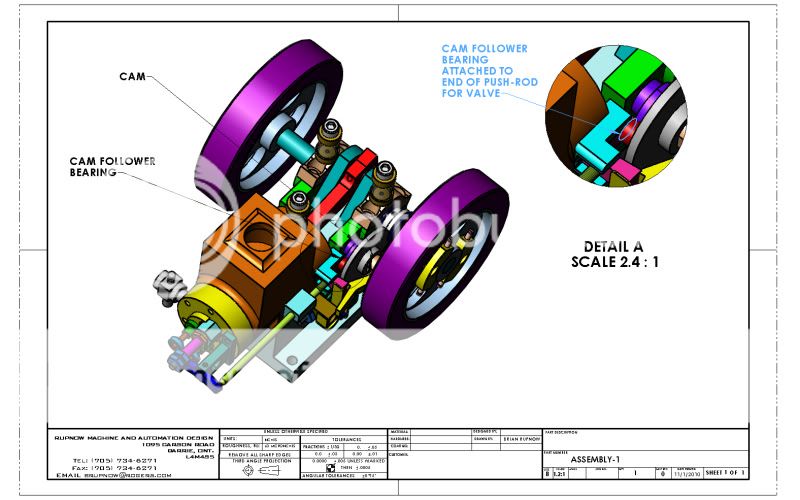
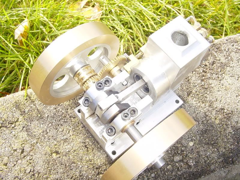
Todays efforts produced the cam and the spool which the arms on the governor weights and the "miss lever" ride in. The pushrod can be adjusted---This doesn't change the lift of the cam, but what you want to achieve is a few thou clearance between the end of the pushrod and the rocker arm when the valve is closed---just to be sure its closing on the valve seat and not being held partially open by the pushrod riding on the non-lobe part of the cam. If I want to adjust the cam for less lift, will simply sandpaper a little bit off the high point of the lobe.
camandspoolfinished001.jpg

 
Nice shot there Brian!
You've got some very good looking parts.
(Well, I mean the whole engine looks great!)
 
Just had a very pretty witch and Scooby-doo show up at my door looking for candy!! My grandkids---Hannah the witch and Makayla the Scooby.
Halloween-2010005.jpg
 
Ain't grandkids just the greatest thing in the world?

By the way, I guess the horse is already out of the barn, but, there is a similar method for making a cam in the mill where you you mount the blank on a rotary table, off center as you did with the lathe. Then you use a boring, cutting on the inside. You make a vertical pass to cut off one side, then you rotate the rotary table 5 degrees, and make another pass. Repeat until you are all the way around except for the lobe.

Look at reply #52 here where I made the cam for my plumbing parts engine using this method...

http://www.homemodelenginemachinist.com/index.php?topic=6352.150

Chuck
 
Thanks Chuck---Greatest thing in the world, and I'm getting our first grandson sometime in February!!! I remembered seeing your post on cam making in the mill when you posted it, but I couldn't really understand it. Now after todays effort and rereading your post, it makes perfect sense. I like your method much better, because it gives you great control over how many degrees the cam is rotated each time. I found my attempt in the lathe today to be absolutely asinine!!! If I have to redo the cam,I will use your method. I will be setting up my rotary table tomorrow morning to make the part on which the counterweight arms pivot.---Brian
 
That picture is priceless. Truly one of the nicer things in life and certainly the best thing about Halloween are the youngsters in their costumes. The younger kids just seem to make the outfits have a life all their own.

BC1
Jim
 
Brian, just to give credit where it's due, the cam cutting method using a milling machine and rotary table came from Randall Cox and his Open Column Six engine which was published in Model Engine Builder, Issues 1 & 2.

Chuck
 
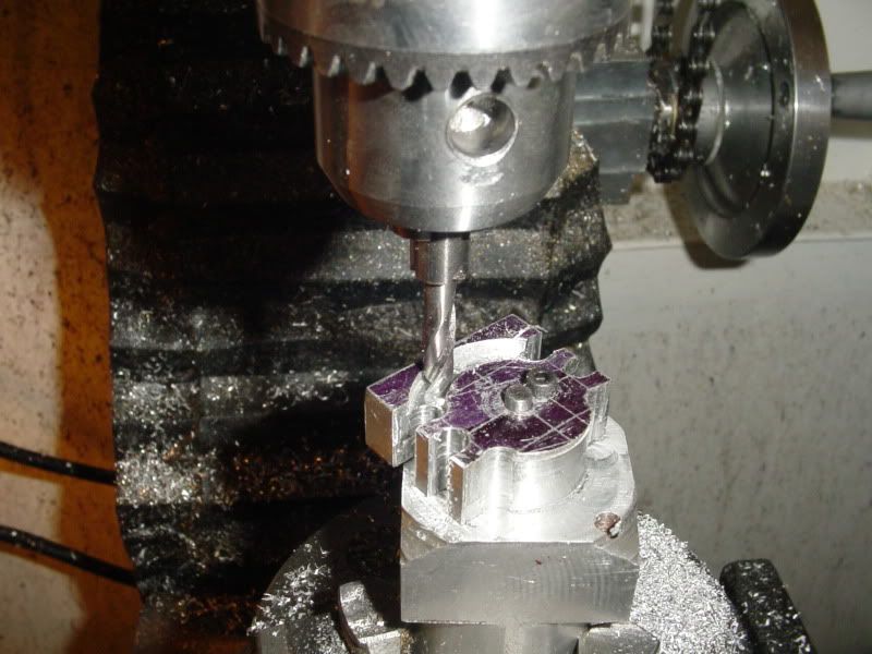
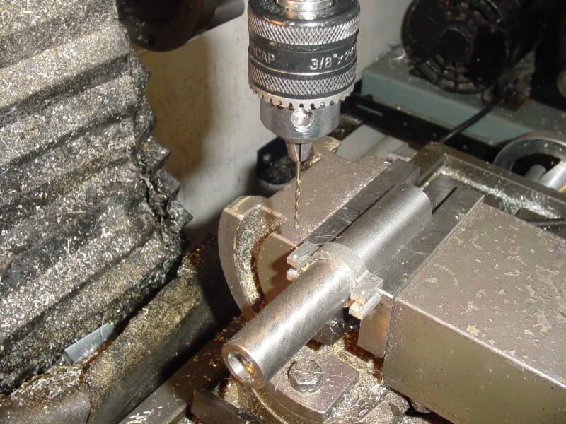
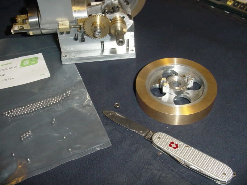
Today was spent building the "Yoke"---This is the part which rides on the inside hub of the governor side flywheel and provides a place for the counterweight arms to pivot from. Nothing really exotic here, but some nice rotary table and 4 jaw chuck work. After I had finished machining it, I had no real good way to hold it for drilling the pivot holes, so I loctited it to a peice of shaft, then leveled it in my mill vice both horizontally and rotationally to drill the two 1/16" dia. pivot holes. Then a bit of heat from the torch was applied to make the loctite let go, and I pulled it off the shaft with my gloved hand. In the last picture, you will see it mounted on the flywheel. Also in the picture is the worlds smallest sealed ball bearing to become my cam follower (Roto-Precision part Number SI-418ZZ07) It is 1/8" i.d. x 1/4" 1.d. x 3/32" thick----(I couldn't buy a thicker one in that bore and o.d. range). While I was at Canadian Bearings picking the small bearing up, I bought a bag of 100 steel bearing balls, 1/8" diameter. I needed 2, so will have 98 left over---If you need any for your Kerzel build, let me know and they're yours---.
collarforctwtarms003.jpg

collarforctwtarms005.jpg

collarforctwtarms006.jpg
 
I'm considering a change to Kerzels ignition system. Although his probably worked fine, I find the idea of soldering bits of tungsten to spring steel to make a set of ignition points and combining the valve timeing cam with the ignition timeing cam just a tad hoaky. On my Webster engine I used a set of ignition points and a condenser out of an older Chrysler product, and they worked just find. I've got tons of room on the non governor side of the engine, where I can put a cam between the flywheel and the engine body and sneak a set of points in there too.
 
Looking good Brian,

I think I'll need to pay special attention to these tiny governor parts if I'm ever to do a hit & miss. I know you've done this sort of thing before.

I think using some commercial points is a good idea as you know they'll work and for this application should last forever.

Nick
 
I like your locktite trick Brian. I need to keep that in mind when funny situations arise.

What are the ball bearings for? I cant for the life of me figure it out.

I dont mean to rain on your parade, but I think this bearing is a tad smaller.

http://www.globalspec.com/pix/VerticalNewsletter/med/Dynaroll_v4i9med.jpg

http://www.globalspec.com/FeaturedProducts/Detail/Dynaroll/Precision_Ball_Bearing_Diameter_20mm/99675/1?isPastIssue=true&id={id}&email={email}&md=090618&mh=ee4c12&Vol=Vol4Issue9&Pub=35&LinkId=444089&keyword=link_444089&vid=159499&frmtrk=newsletter


Kel
 
GUYS, GUYS--I was being facetious!!! I know its not the smallest bearing in the world. but ya gotta admit, its pretty damn small.---And here's where it goes---
CAMFOLLOWERBEARINGONENGINE.jpg
 
Yeah, I knew where the little ball race was going, but I haven't figured the two 1/8" balls - non-return valve in the fuel line?
 
I think the balls will be soldered to the ends of the governor arms and run in the spool grove.

J
 
On Kerzels detail of the rocker arm there are two 1/8" dia. steel balls loctited into the underside of the rocker arm where it bears against the pushrod and the stem of the valve. I just clicked on his site this morning and it isn't working. I hope it hasn't dissapeared off the internet, but no fear, I have all the drawings copied and transcribed into Solidworks if they have.---Brian
 
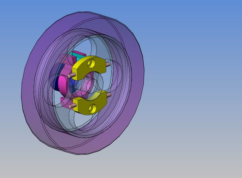
Today I worked on the little bits and peices that are the heart of a hit and miss system. I didn't take any "in process" shots, because its only normal milling and turning and tapping---very finicky milling turning and tapping, mind you, but nothing really picture worthy. For those of you who are curious about the mechanism, this solid model shows all the bits in relationship to each other. Centrifugal force makes the weights fly out away from the crankshaft centerline. The weights are attached to arms which pivot, and the pivoting motion causes a spool to slide in a linear motion along the central axis of the crankshaft. A lever is trapped in the OTHER groove in the spool (its not shown here) and this lever is what props the exhaust valve open, causing the engine to "miss" untill it slows down and a pair of springs (again, not shown) pull the weights back in close to the crankshaft. This slides the spool back to its original position and the lever "unprops" the exhaust valve, causing the engine to fire and repeat the cycle.
SUBASSEMBLYGOVERNORANDFLYWHEEL-1.jpg

.
 
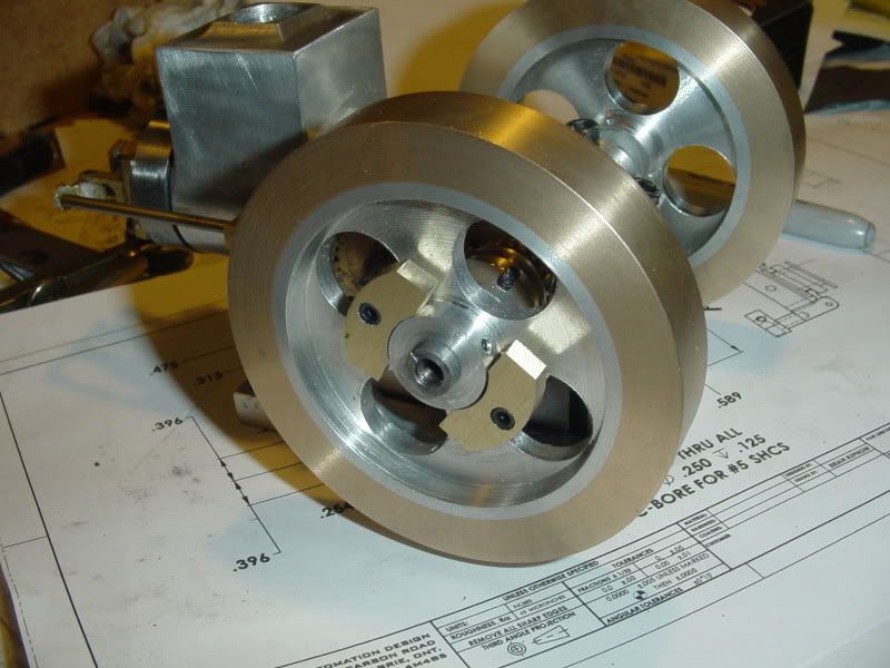
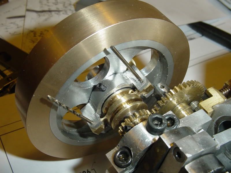
These pictures show the govenor weights from both sides of the flywheel in the "low speed" mode, in which the engine would be able to fire.
governoronengine003.jpg

governoronengine004.jpg
 

Latest posts

Back
Top