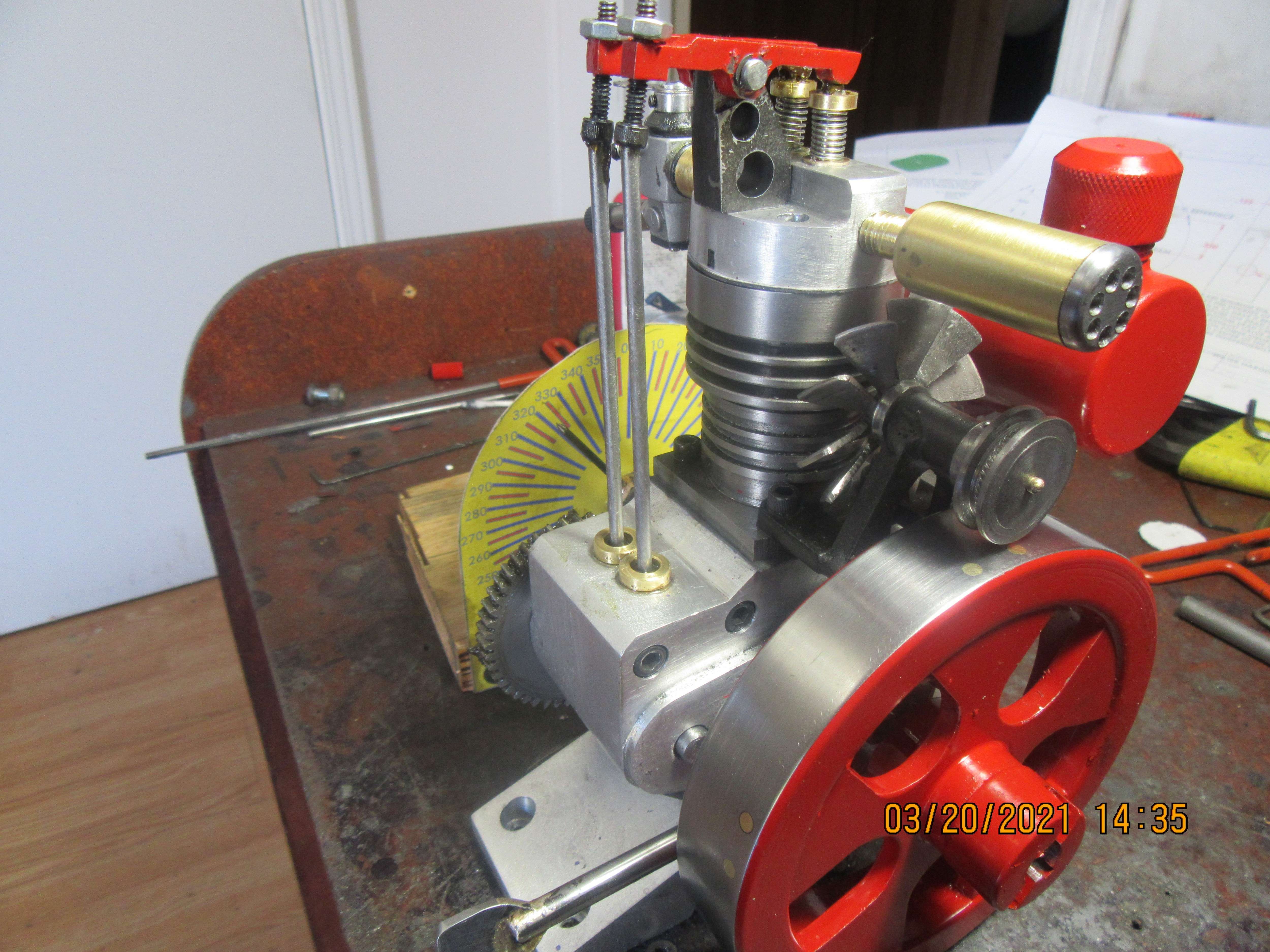
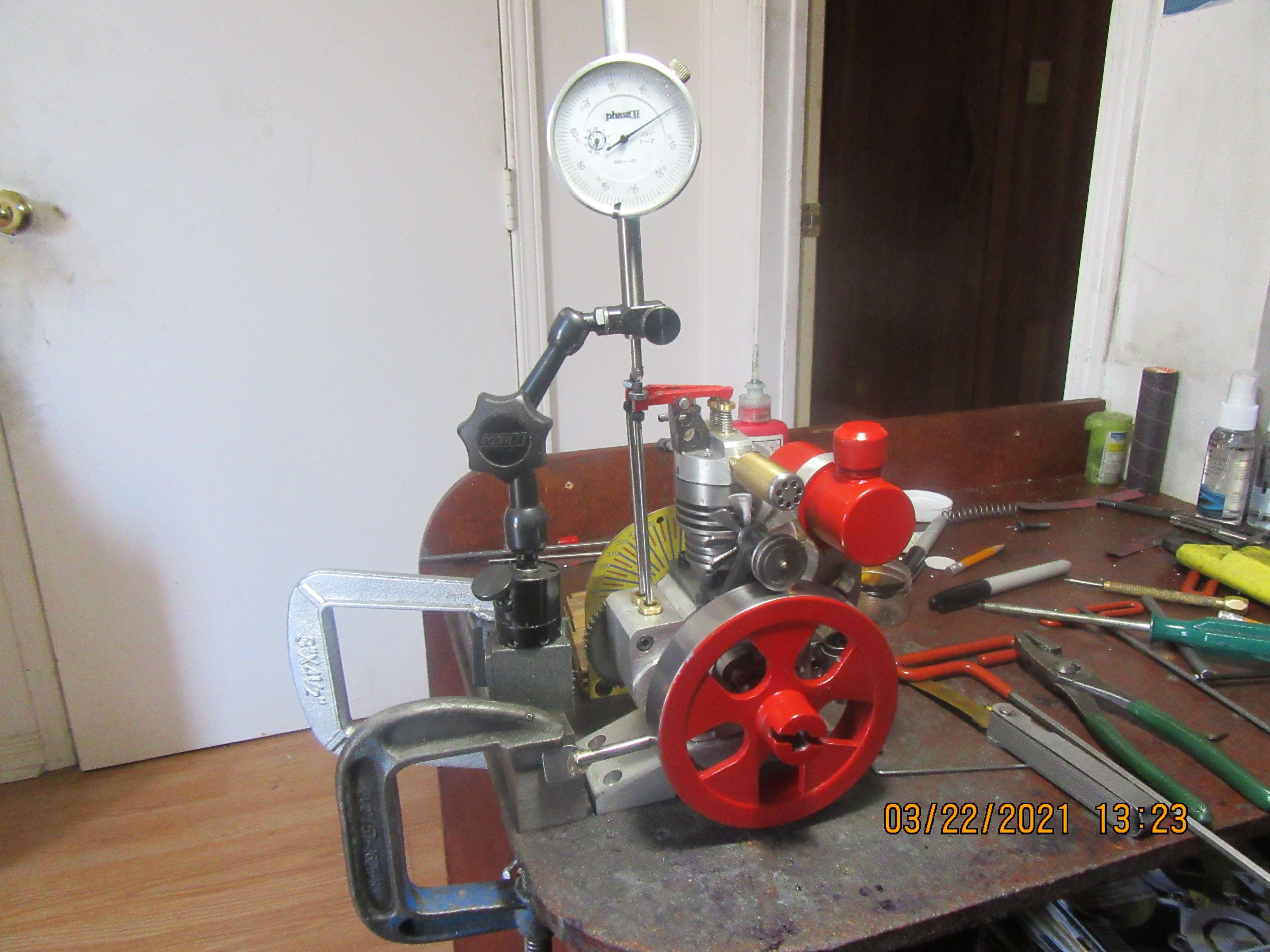
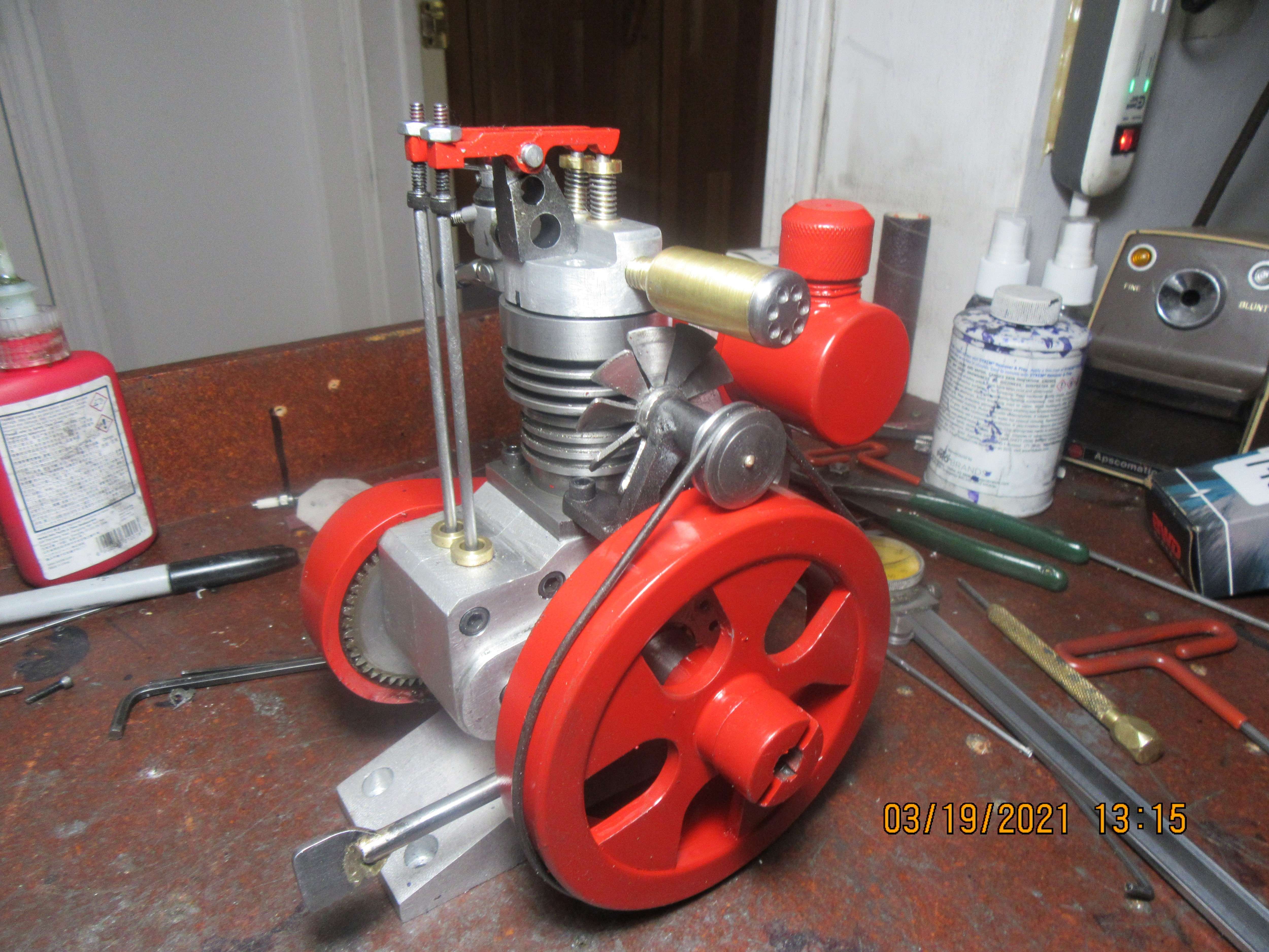
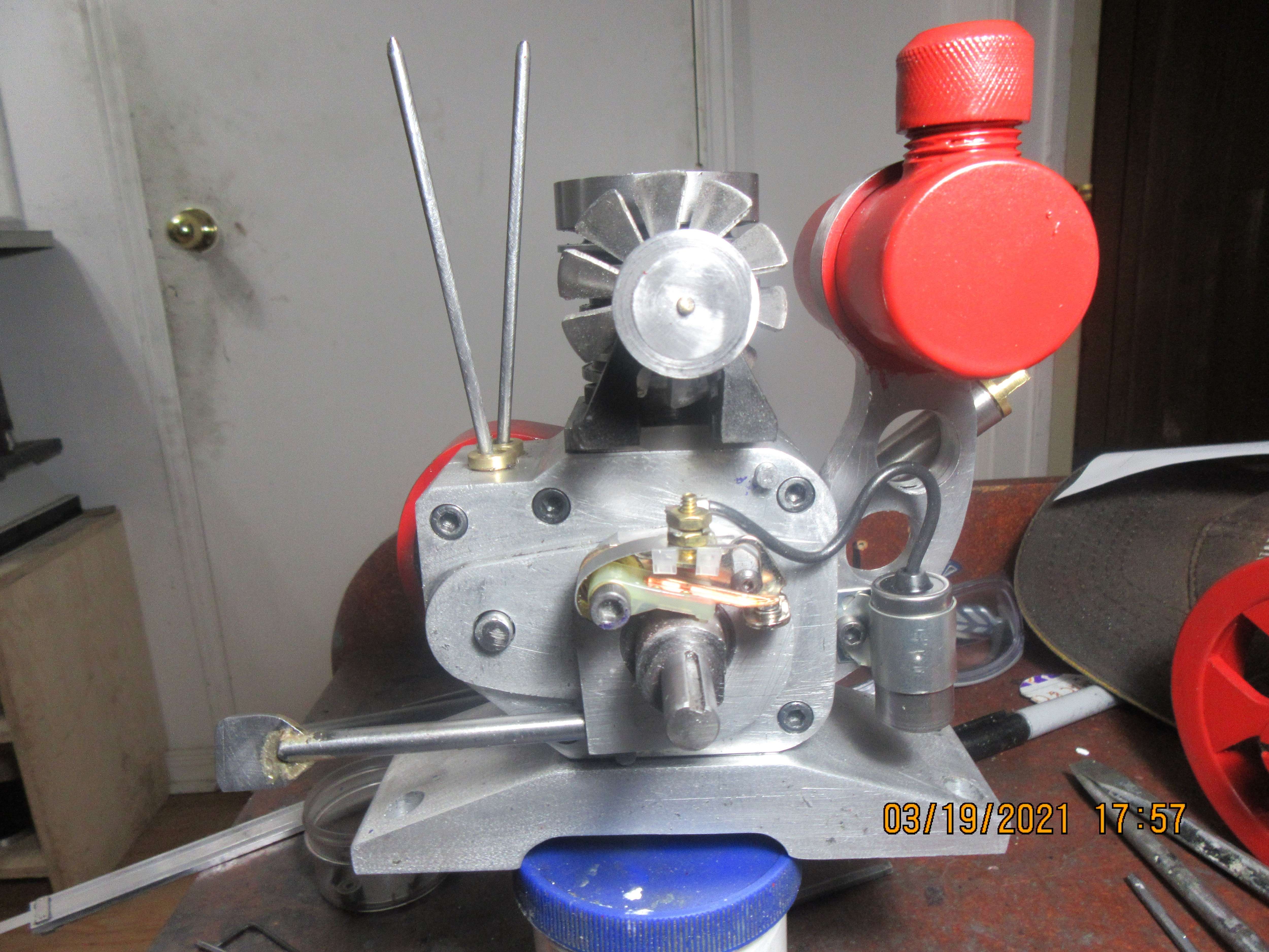
Okay, working with the cams I have made, (which have 120 degrees of angular contact ) that means that it affects 240 degrees of crankshaft action. so, I begin to open the intake 15 degrees before top dead center and it closes 45 degrees after bottom dead center. the exhaust begins to open 30 degrees before bottom dead center and closes 30 degrees after top dead center. The angular difference between the cam lobes is approximately 100 degrees when fixed in place on the cam shaft. The following bit of arcane knowledge is something i researched and read about a few years ago when I built my opposed twin i.c. engine.
Now let me see if I can get my head around this. The piston is moving from top dead center to bottom dead center on the power stroke, with both valves closed. 30 degrees before bottom dead center, the exhaust cam which is leading begins to open the exhaust valve. Since there is a 1:2 relationship between crankshaft revolution and camshaft revolution, that translates to 15 degrees of camshaft rotation.
As the piston reaches bottom dead center and begins to travel up on the exhaust stroke, the exhaust valve stays open during the full upwards travel of the piston which represents 180 degrees of crankshaft rotation, or 90 degrees of camshaft rotation. Then as the piston reaches top dead center on the exhaust stroke, the exhaust valve stays open for 30 degrees of crankshaft rotation (15 degrees of camshaft rotation) during the intake stroke before it fully closes. This adds up to a total of 240 degrees of crankshaft rotation, or 120 degrees of camshaft rotation.
So—Let’s back up a little bit to where the piston is coming up to top dead center on the exhaust stroke with the exhaust valve wide open. 15 degrees of crankshaft rotation (7.5 degrees of camshaft rotation) before the piston reaches top dead center, the intake valve begins to open. It stays open thru the full intake stroke of the piston (180 degrees of crankshaft rotation, 90 degrees of camshaft rotation, and then as the piston reaches bottom dead center on the intake stroke and begins to move upward on the compression stroke, the intake valve stays open for an additional 45 degrees of crankshaft rotation, (22.5 degrees of camshaft rotation.)
This adds up to a total of 240 degrees of crankshaft rotation, (120 degrees of camshaft revolution).
So---we see that the exhaust cam and the intake cam must in this case have the same profile, since they must both be “active” an equal number of degrees of rotation. We also see that there is a total of 45 degrees of overlap at top dead center where both intake and exhaust valves are open at the same time.---this is typical of a “mid-range power/speed” engine. Hi speed/ hi-performance engines can have a greater overlap, while slower running engines must have a smaller overlap.
Now, there is a marvelous calculation used to position the intake and exhaust cams rotationally in respect to one and other. I have read this calculation enough times to make my head explode, and will repeat it here:
“Take the total of the valve open periods, divide by 2, subtract the total valve overlap and divide the result by 2”
So—the total of the valve open periods is 480 degrees of crankshaft rotation, divided by 2= 240 degrees.
240 degrees -45 degrees of overlap=195 degrees. Then 195 divided by 2=97.5 degrees of rotational separation between the intake and exhaust cam lobes.
This information was gleaned from a number of sources, but primarily from information found in “Model Four Cycle Gasoline Engines” by C.L. Mason and in “Miniature Internal Combustion Engines” by Malcolm stride.
I laid this out in 3d cad, independently, and came up with a lobe separation of 97.43 degrees, which confirms the long winded mathematical approach.




![MeshMagic 3D Free 3D Modeling Software [Download]](https://m.media-amazon.com/images/I/B1U+p8ewjGS._SL500_.png)


![DreamPlan Home Design and Landscaping Software Free for Windows [PC Download]](https://m.media-amazon.com/images/I/51kvZH2dVLL._SL500_.jpg)


