1" Bore x 1" Stroke Vertical i.c. Engine

Home Model Engine Machinist Forum

Help Support Home Model Engine Machinist Forum:

This site may earn a commission from merchant affiliate links, including eBay, Amazon, and others.
Thankyou Brian, for sharing this. I haven't got the gear nor the need - nor bottle - to try gear cutting. But I do enjoy and appreciate your honesty in sharing your mistakes and all the guys who jump in to help and advise. This is a humbling but enjoyable experience witnessing kindness in text to help you resolve your problems. (I didn't ever expect you to have any such issues - it is like finding out that Teacher is a normal person!).
Hope the hands are getting better?
K2
 
Brian,
I realize that. I believe whats important to you is the description on page 4 and 5 relating to the number of holes to be included in the set up of the span of the shear / sector arm to indicate how many number of holes should be included when setting up the sector arm for the correct number of holes. The way you went about, you included one hole to much and should have done 15 holes plus the one the pin was in, i.e. the span of the sector arm would have included 16 holes total - 15 open holes and one hole where the locator pin is in. You weren't sure about that and I hoped the Little Machine shop article would help with that.
Peter J.
Peter, what you are describing would be correct if he needed to move 15 holes at a time, but that would result in the ratio of 1-15/20 = 1-3/4, which would give 51.4 teeth. He needs to move 16 holes at a time, so 16 + 1 for the pin between the sector arms.
 
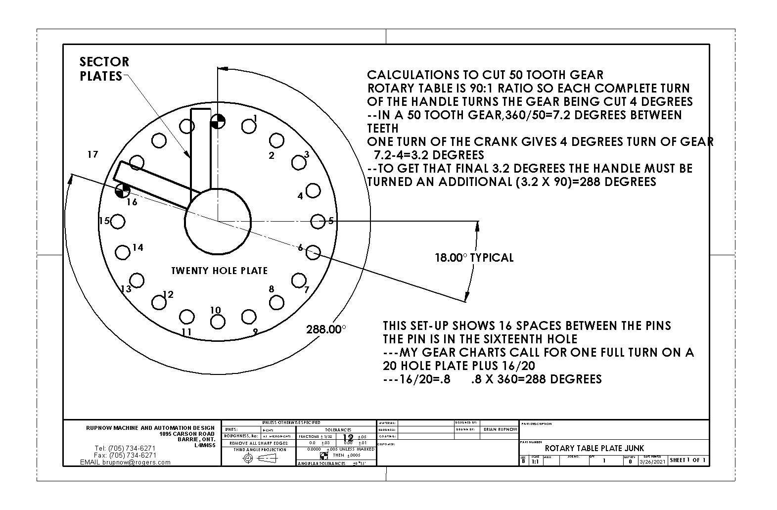
After much head scratching and reading the responses on three different forums, I come up with this. The math appears to be correct. On the first gear I cut which ended up with 48 teeth and not the 50 I was aiming for, I was going one space too many before each cut.
What I have shown here is what the correct set-up should have been to get 50 teeth.
r0GfB1.jpg
 
I don't want to beat this horse to death, but I can't resist one more post.

The problem with relying on charts has been described above: the charts are based on a table with a certain ratio in the worm gear. If your table doesn't match that ratio, the charts will be completely, utterly wrong. A secondary issue is that you may or may not have the same set of indexes as are covered in the chart.

That is why I depend on the math rather than on any charts - that, and because the math is really rather simple. Let's take a dividing head with a worm gear ratio of 60:1. None of the charts mentioned above cover this table ... but not to worry. I want my gear to have N number of teeth in one complete revolution. How many complete turns of the handle will it take to achieve one complete revolution of the gear blank? 60 - because the worm ratio is 60:1. So I need to divide those 60 turns by the N teeth that I need to cut: 60/N. This tells me exactly how much I need to turn the handle for each tooth.

Let's say that my goal is 32 teeth. If I plug 60/32 into the calculator, I get 1.875 - but this is a place where fractions are better than decimals, so let's do it the old fashioned way; 60/32 = 1 remainder 28, or 1-28/32, which can be simplified to 1-7/8. Now I just need to find an index circle based on a multiple of 8 - 16, 24, 32 ... any of these will do. For whatever index circle I use, I will convert 7/8 to match: 14/16, 21/24, 28/32. So if I use a 24 hole index, I will need to turn the handle 1 full revolution plus 21 holes.

As discussed above, that means I need to set the sector arms up to span 22 holes - one for the current location of the index pin, and then 21 more to achieve the desired 21/24 ratio.

Okay, describing it like this above, I have to admit it may sound complicated. But really, the key is to remember that you want N teeth out of R revolutions of the handle, where R is the ratio of your dividing head.
 
There is also the problem of a couple of charts that come with the imported R/Ts have one or two errors in them
 
So just put a bigger flywheel* on it, stick your nose in the air, and explain to people that it's a 4800 stroke engine. An external valve that swaps the exhaust with the intake when the cam is exactly 180 degrees out of what it should be might be a good idea, but then it'll be a 2400 stroke engine.

* much, much bigger.
 
Or throw in the towel, use a 1:1 gear ratio, and put pen clickers in your lifters: Engineers Explain How Click Pens Work - Pen Vibe

(And if the facetiousness irritates rather than amuses -- say so and I'll try to stop. It's just that you've gone and made exactly the kind of mistake that I might have, so I'm abusing you with exactly the kind of humor that I'd aim at myself in a similar situation).
 
As far as I know, I made this gear using exactly the same math inputs as all my other gears. I didn't end up with any half teeth or unusually thick teeth. That's why it is such a puzzler. I have made many, many gears and never had a problem. I made this exact same gear for the Rockerblock engine and it has the correct number of teeth. If I made any mistakes with this gear it was probably from using one space to many on the divider plates. I'm going to make it again this afternoon using the information in the drawing I posted. I will let you know how that turns out.---Very, very weird!!!
 
Don't beat yourself up over this one Brian. Use the "age" excuse and say " can't remember what I did". It gets sympathy as well as the help everyone is providing. I am now old enough to get away with that one, and I assume you are my Senior?
Whatever, this has been a most interesting thread because things didn't come out right first time. And very educational for amateurs like me!
Thanks,
K2
 
Quadrant should be set to have 17holes between the fingers. 1 for the pin and the 16 you need to move

If you set the quadrant to one hole too many you would have moved 4deg + (17/20) x 4 = 7.4deg spacing which gives about 48.5 teeth so you may have had some slip an the arbour too.

here is a Video I did to go with my "Milling for beginners" book/articles you can see there are the 6 holes required plus the one the pin goes into between the fingers.


One note that I would add to this video for the sake of beginners: don't forget that rotary tables and dividing heads have some backlash. As a result, you never want to "back up" to the desired position; always move forward so that the backlash is taken up. (If you overshoot, move backwards far enough to go past the backlash, then come "forwards" to the desired position.)
 
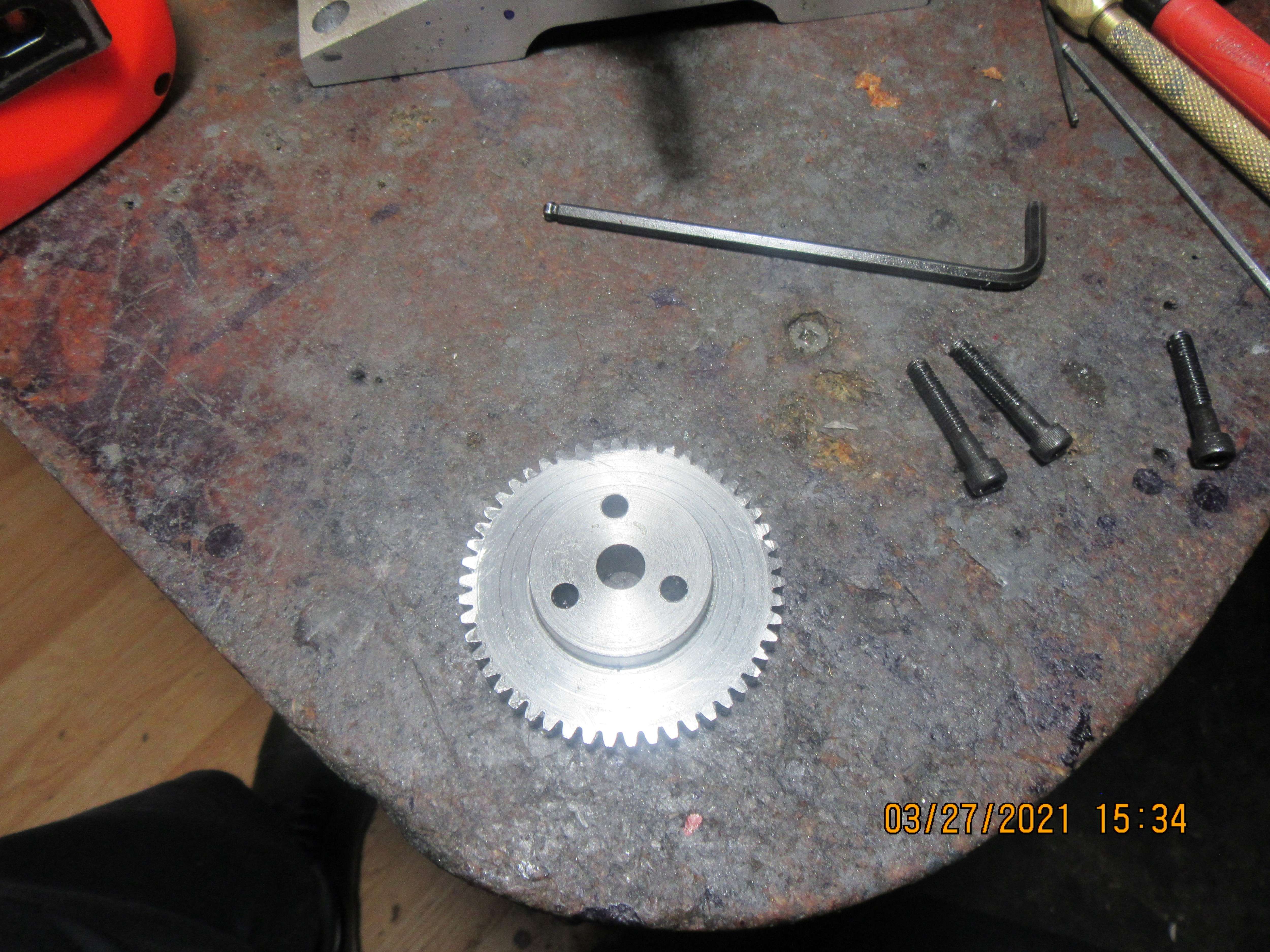
Okay--Here we go, second time around!!--And this time it has 50 teeth, and it meshes fine with the 25 tooth gear on the engine, at the correct centers for a 25 tooth and a 50 tooth gear. Why did the other (first) 50 tooth gear end up with 48 teeth?---I have absolutely no idea. The blank size was the same, the material was the same. I must have set the sector arms at one hole more than they should have been set at on the 20 hole divider plate. That is the very first gear that I've made that didn't come out right---I've cut about 40 gears prior to the bad one. We'll remember that gear forever now, and double check my machine settings before I make any more gears.
LHhpoO.jpg
 
No, that gear is too weird to keep around. If I keep it, sooner or later I will use it and then not be able to figure out what happened to my gear ratios. Into the garbage with that sucker. I have a hard enough time remembering the things I do right without having to remember the things I did wrong.
 
No, that gear is too weird to keep around. If I keep it, sooner or later I will use it and then not be able to figure out what happened to my gear ratios. Into the garbage with that sucker. I have a hard enough time remembering the things I do right without having to remember the things I did wrong.
Why not just mark on it with indelible ink the number of teeth and hang it on the wall?
 
Bury it Brian and mount it on the cross. Those fairies at the bottom of the garden are the culprits they sneak around at night and change settings. they have been to my place too, sometimes often. John
 
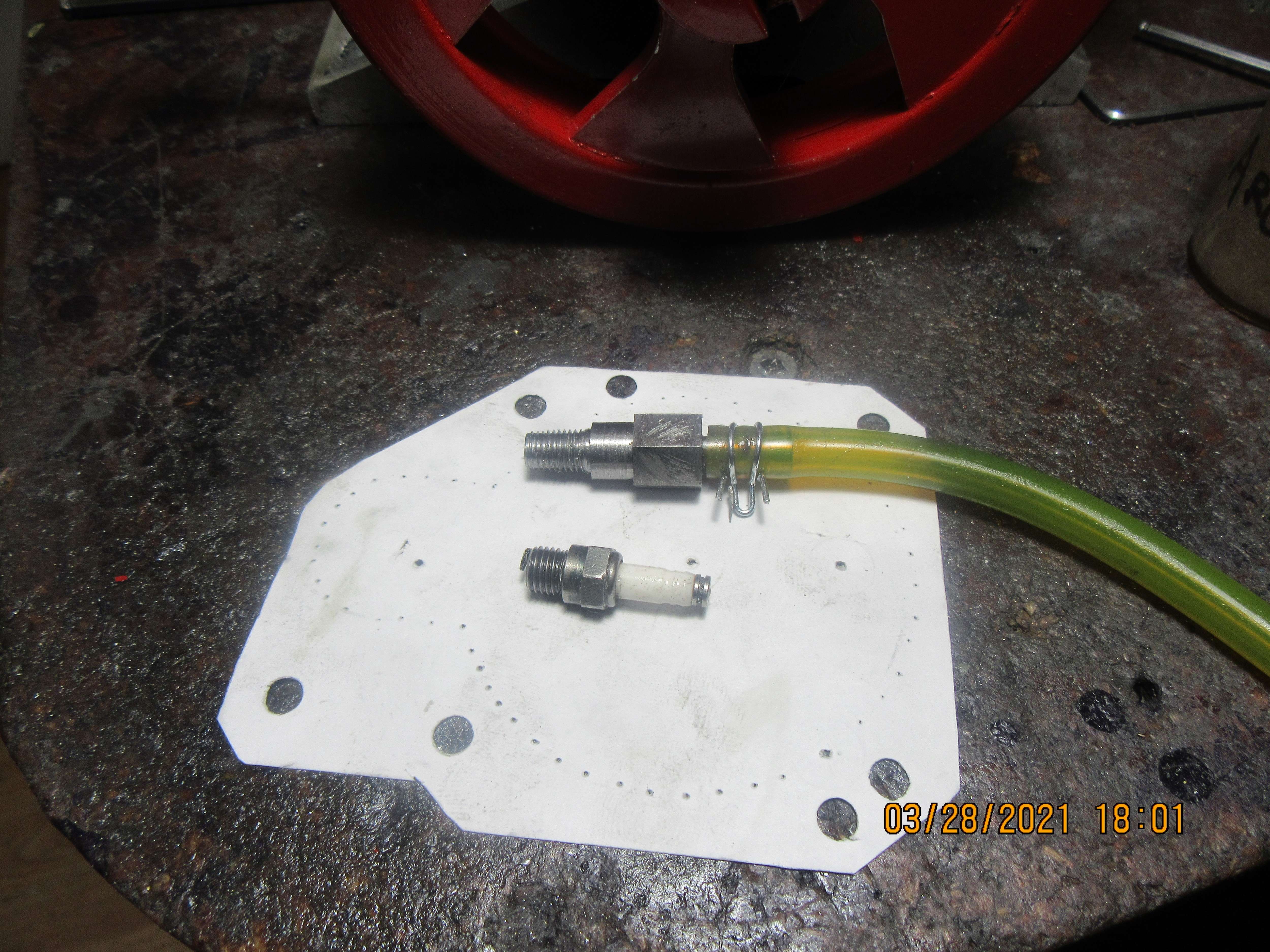
Engine is reassembled and almost ready to go. Today I took a bit of time and made an adapter with 1/4"-32 threads on the end, which will screw into the sparkplug hole. It is hollow, and has an airline attached to it. I will screw it into the sparkplug hole tomorrow and hook a regulator onto it and apply some air pressure. This will let me see if I have any leaks in the intake or exhaust valve or around the ring.
BMeqCj.jpg
Brian did you single point that thread?
 
This morning I screwed my new adapter into the sparkplug hole and cranked up the pressure on the air regulator. This pressurized the cylinder, and immediately showed a massive head gasket leak. There is a ring of material about 0.080" thick on the cylinder head that fits into the top of the cylinder to locate it accurately, and somehow when I tightened the head bolts I had the cylinder head "cocked" enough that it didn't squeeze the head gasket evenly all the way around. This was remedied by removing the head and trimming away a bit of the gasket, then reinstalling the cylinder head and tightening the bolts properly so that the head gasket was held tight all the way around. Next thing that showed up was that I didn't have enough clearance between the exhaust rocker arm and the pushrod, so the valve was never closing. A bit of adjustment fixed that. That was the only major air leaks that were showing up on that test. Next, I filled the gas tank with Coleman fuel and turned on the ignition, and cranked the engine over with my variable speed drill. It did suck the fuel up thru the transparent fuel line, and it gave a few rather anemic blasts of smoke from the exhaust and was firing, somewhat erratically. Okay---I'm good with that for preliminaries. Going to eat some lunch now, and hope for better results this afternoon.
 

Latest posts

Back
Top