Verical hit and miss engine

Home Model Engine Machinist Forum

Help Support Home Model Engine Machinist Forum:

This site may earn a commission from merchant affiliate links, including eBay, Amazon, and others.
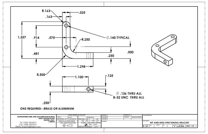
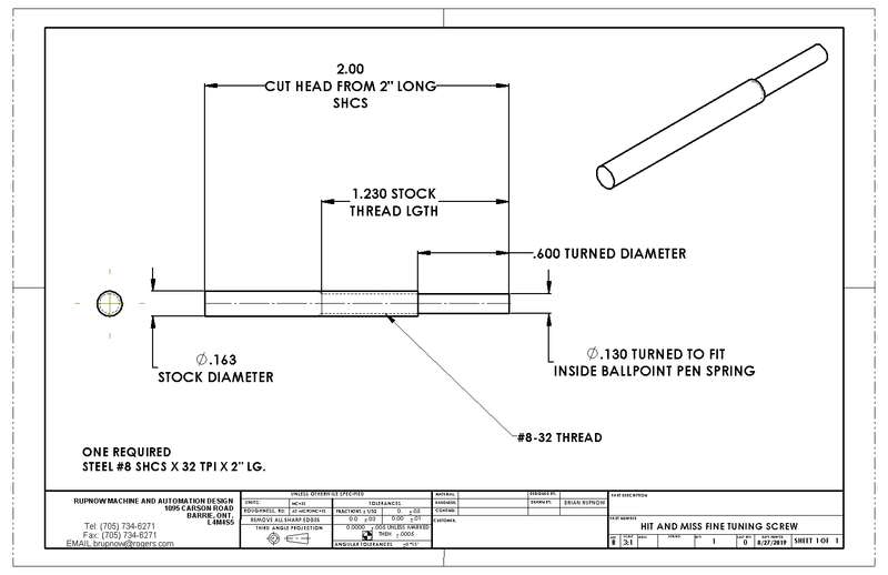
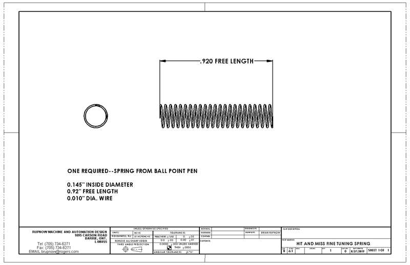
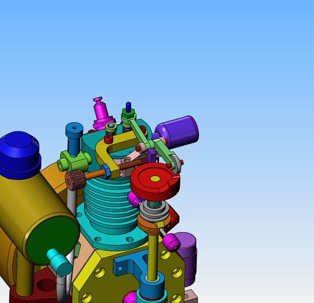
I'm in thinking cap mode this afternoon. As the engine sets right now, there are only two ways to adjust the speed at which the engine kicks in and out of "hit and miss" mode. One is by changing the weight of the governor balls, and the other is by changing the strength of that light green spring on the vertical cam shaft. I think the governor balls are very close to the correct weight right now. The light green spring is a real pig to change, requiring almost complete disassembly of the cam shaft and brackets. However--If I were to add a third factor into this, I believe I could fine tune the kicking in and out of "hit and miss" mode. The way the engine works right now is that once the engine reaches a certain speed, centrifugal force makes the balls fly outward away from the cam-shaft (as it is shown in the model). The cams on top of the governor arms force the grey governor thimble upwards, compressing the light green spring and in turn makes the dark blue "hit and miss lever" rotate and end up underneath the rocker arm, which prevents the exhaust valve from closing. It works great, but I have no control over when this happens. If I were to make the yellow bracket which bolts in place with two of the head bolts, then I could tap a hole in it, and add the bronze colored adjustment screw and lock nut. The spring from a ball point pen would be Loctited to the bronze threaded adjustment screw, and the other end would bear against the dark blue "hit and miss lever". Any pressure applied to the "hit and miss lever" by the spring would counteract the force applied by the light green governor spring. This should give me the ability to fine tune the rpm at which the engine kicks in and out of "hit and miss" mode.
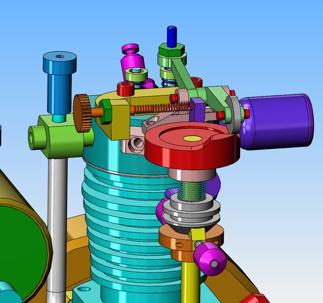
G7fhM5.jpg


Why not just add a collar with set screws on top of the green spring? Just leave enough room above it for height adjustments.

Or if you know the spring is too strong, pull out the top or bottom winding enough to snip off 1/2 to 1 coil at a time. When it is right, just stop. Disadvantage to this method no ability to easily reverse a change. The movable collar is an easy and adjustable solution.
 
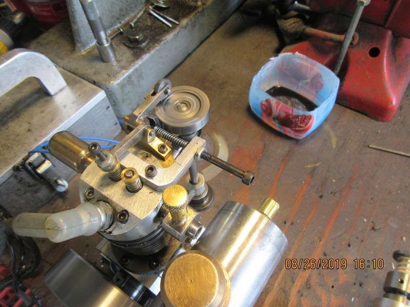
It works!!! I have attached a still picture and a video showing my "fine tuning adjustment screw" that affects the rpm at which the engine kicks in and out of hit and miss mode.

qsNEbT.jpg
 
I've never had a real problem getting engines to run fast. I like my engines to run slow, and it takes more fiddling to get them to run slow than fast. In a perfect world, I'd like the hit and miss engines to fire once, then coast for seven or eight revolutions, then repeat. I have came to the conclusion that although Viton rings seal extremely well, the penalty for using them is that they create more drag on the piston than cast iron rings. This drag has a rather dramatic effect on how many coast cycles a hit and miss engine will have before it hits again. This engine has a pair of cast iron rings that purchased, and it does seem to have an improved coast cycle. The only thing wrong with having them run as slow as I like is that they lose the ability to take over and keep running when a load is applied.
 
I think it would be worth your time to make another piston with some small amount of clearance with the bore. You know your cast iron rings are sealing now, so you don't need the piston to be lapped in tight. I believe removing the drag the lapped piston is generating will further improve the number of coasts you get between misses, as well as increasing engine power at low RPM. I know it's a pain to do but I think it'll provide the results you're looking for.
 
Brian,

Kudos for continuous experimentation and the resulting improvement on this engine. I certainly like the way it operates and sounds now, even though I was impressed with this one quite a few posts ago.

I am also mesmerized watching the governor-weight arc change in response to the hits and misses, proving that is working very well. I have been following all of your projects with fly-ball governors and I am always entertained by them.

Thanks again for your contributions to these forums,

--ShopShoe
 
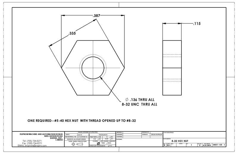
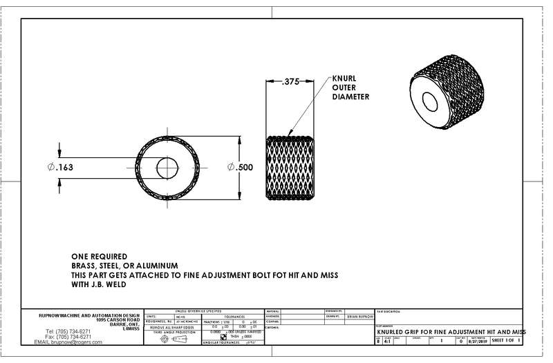
The people who have purchased this engine plan set will be interested in details of this fine tuning adjustment for the hit and miss function. Rather than email every individual, I will post it here.
d7kGjt.jpg

0mCWWQ.jpg

XgkhS8.jpg

qx1hD3.jpg

SeQhct.jpg

ssbBKQ.jpg
 
That's a nice solution Brian & seems to work very well.

Being a CAD "junkie", I have to ask how you modeled the knurl on the screw. A revolved/patterned cut? Or does solidworks have a better & more elegant solution?

Sweet engine Brian,

John
 
Johnmcc--Solidworks doesn't have a "good way" to add a knurled surface. I modelled the round blank with the hole in the center on the front plane. Then I started a sketch on the front plane, drew a circle the same diameter as the blank, then went to annotations and added a helix while still in the sketch. then I flipped it over to the top side and started a sketch. I drew a very small rectangle, and used the pierce command to attach it to the helix. Then I used the "swept cut" command to chase the small rectangle around the helix. Then I used the pattern feature to pattern that cut 10 times around the diameter. Then I repeated all of the steps, only I chose the "reverse rotation" feature. It gives a rather strange looking knurled pattern, but it shows up well on the part and on drawings.
 
I'm still thinking about a mechanism which would automatically give a variable load to the hit and miss engine. The idea of an offset weight mounted on the end of a rotating arm is great, except for one thing. When lifting the weight against the pull of gravity, the engine would be forced to actually "work". However, once the weight went "over center" and began to drop, that force would feed back thru to the engine, which is what I want to avoid. I could use a one way clutch bearing so the drive wouldn't feed back to the engine while the weight was swinging down under the force of gravity, but there is no way to predict when it will stop swinging. A few years ago I was messing around with worm gears. I had read about making your own model sized worm gears, and wanted to try it for myself. I was impressed by how well it worked, and created the following thread.
http://bbs.homeshopmachinist.net/threads/63038-Fun-with-Worm-Gear-Drives?highlight=worm
The interesting thing about a worm gear, is that once you get beyond a 40:1 ratio, they won't feed back to the driving shaft. This feature has been successfully used on many small hand winches. I still have the worm drive created back in 2014, and I may do something with it.
 
I could use a one way clutch bearing so the drive wouldn't feed back to the engine while the weight was swinging down under the force of gravity, but there is no way to predict when it will stop swinging.

It won't stop swinging. Well, it eventually will but that could take hours.

Other than a mechanical brake, which would be tricky, it's just not stopping.
 
Just to let you know I've made a start Brian and I will start my own thread when I actually get going . This is about 2 and a 1/2 hours cutting with my
little 6x4 horizontal band saw .Got the bevel gears also.IMG_20190901_135550.jpg
Cheers
John
 
John--I'm glad you were able to get the gears. I am looking forward to someone starting a thread on their build.---Brian
 
CFL Bob-it will stop swinging, but I don't know where. Once the arm has reached the top of it's arc and began to fall under the influence of gravity, it will "free swing" 180 degrees, then it's momentum will carry it past the bottom of it's arc and that is the circumstance where I "don't know". I have no way of knowing how far past the bottom of the arc it will swing. As soon as it stops "free swinging" the engine will pick up the load again because the engine is still running--it never stopped. I have an arrangement set up in the garage which I hope to finish today using a worm gear. If it works I will post a video. If it doesn't work, I may buy an one way clutch bearing.---Brian
 
A very important milestone reached today. You have all heard me making reference to my "Fat mans walk" which I started after getting a "too high" blood sugar report on a blood test. I have been walking a mile a day since then, and forgoing my regular intake of chocolate bars, donuts, soft drinks, and any other sweet things. As of this morning I have lost 30 pounds. I find that fact amazing. After three months of such extreme dieting and exercise, I'm finding it more and more difficult to stay on such a monastic diet. I have already told my wife months ago that if I ever lost 30 pounds, I was going to go down to the Dairy-Queen and have a banana split. Today could be the day!!!
 
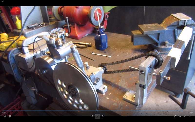
This morning I ran the engine with my worm drive varying load. It worked, but not as well as I wanted it to. I made a video, but I'm not happy with the results. The big weight (two pieces of flatbar taped together) did make the engine run in the miss cycle at a very brief angle near the top and bottom of its swing, but when the offset weight went over the top of it's arc, it still resisted turning easily. So, while the engine should have been popping and missing thru the full 180 degrees of swing as gravity pulled the weight down, it kept on hitting trying to overcome the worm gear and worm binding. Engine was supposed to miss under no load condition for 180 degrees of arc while gravity pulled the arm down and then work without missing while the weight was lifted up thru 180 degrees. It didn't work out that way. I have just ordered a one way clutch bearing, and when it gets here we will try things again.
z3xKxP.jpg
 

Latest posts

Back
Top