Verical hit and miss engine

Home Model Engine Machinist Forum

Help Support Home Model Engine Machinist Forum:

This site may earn a commission from merchant affiliate links, including eBay, Amazon, and others.
Johno--The plans are for sale now.--Brian
Brian
Please let me know how i can get a set of drawings for you hit and miss
Tks
Jerry McCracken
PS Here is a pic of my car. 5 year build started driving it last year. 34 Ford
 

Attachments

  • 2173B5E9-A3CD-4F6E-99FD-AB499E774063.jpeg
    2173B5E9-A3CD-4F6E-99FD-AB499E774063.jpeg
    171.3 KB
I am curious to here how your cylinders and rings worked out. I saw in your build that you lapped the cylinders. Did you leave them that way or did you need to rough them up a bit to seat the rings.

I had my eyes fixed as you did and it was life changing. I can see perfectly far but need readers for up close. 1.25 power for general use but when at the lathe or mill I keep a pair of 2.5 and 3.5 power readers.

Thanks for another informative build.


Dnalot
 
Aostling and others wanted to see how this engine reacted under load/no load conditions. I don't have any machinery designed to have a varying load, but I did want to show him and others how a varying load affects these model hit and miss engines. So--Turn up your speakers, click the video link, and set back and listen.---Brian

GJoyM6.jpg
 
I lapped the piston into the cylinder and made no other change to either, other than to add the cast iron rings. Engine has extremely good compression. I think the engine would have ran equally well if I had given about.001" radial clearance. The rings work great. Anyone wanting plans, go to Paypal and put $25 Canadian funds into my account under [email protected] and be sure to send me an email giving your name and which engine you want plans for. As soon as Paypal notifies me that the funds are there, I will send you a package of drawings as .pdf files. there are about 70 drawings, and some of them are multiple sheets.---Brian---Jerry McCracken your car is beautiful!!
 
I just listened to my video, and noticed that I spoke in error. The engine under load hits every other stroke, same as any four cycle engine, not on every stroke.
 
Brian,

You probably remember this, too: When I was a kid and the farmers were elevating square bales of hay up to the haymow with the old farm elevator, the engine running it would sound like that whether working or idling. Of course, the "newer" farmers had a PTO driven elevator, or one with a Briggs and Stratton engine.

--ShopShoe
 
Actually, no. I don't remember, but that's mainly because there weren't all that many farms where I grew up. Once I moved away from home and went "down south" to Belleville, Ontario, the farmers were using electric motors on their bale elevators.
 
I am now in that "post building slump" that always follows a successful build. The engine worked great, started and ran almost the first time I tried it, and ran well. I did manage a video showing the engine running under load conditions while lifting a weight. Rather crude, but it did the job. I have had numerous ideas for making a machine to drive that has a variable load, but that is not as easy as you would think. It would have to cycle in and out of the "load" side automatically, but can not transfer any load back into the engine when being ran in the "no load" situation. --In other news, I got stung by a damned bee yesterday. I was mowing my lawn with my garden tractor, when I felt a small "***" in my right hand. I looked down at my hand and seen a big yellow and black bee, and immediately gave my hand a shake to knock it off. The bee drilled me, and damn, did it ever hurt. I haven't been stung by a bee since before my dad died, so it had to be over thirty years ago. I'm not allergic to bee stings so finished cutting the grass and came in the house and held an ice cube against the sting for an hour until it finally quit hurting.
 
If I do build something with a variable load. I want it to be fully automatic. The problem is that when you slow something down enough that it can be easily seen, the motor gains a great deal of torque advantage. When the motor gains a great deal of torque advantage, then you need an even heavier load. And whatever it is, I don't want it to be much larger than the motor. I also don't want the machine to "feed back" to the engine when the engine is in it's "no load" side of the sequence.---thinking---thinking--
 
If I do build something with a variable load. I want it to be fully automatic. The problem is that when you slow something down enough that it can be easily seen, the motor gains a great deal of torque advantage. When the motor gains a great deal of torque advantage, then you need an even heavier load. And whatever it is, I don't want it to be much larger than the motor. I also don't want the machine to "feed back" to the engine when the engine is in it's "no load" side of the sequence.---thinking---thinking--
How about an air compressor with an air operated clutch. Build up pressure and the clutch disengage. Bleed off some pressure and the clutch reengages. An air compressor is just an engine.
 
maybe some sort of grain grinder or mill. when you drop a hand full of hard dry corn kernels in it puts a load on the engine until it s ground through it? then enjoy a pan of cornbread afterwards?
 
Here she is boys, my mother 99 years old today. That handsome (slimmer) fellow with her is myself, turned 73 in July. Drove up north and had a little birthday party at the senior citizens manor where she lives. Good time was had by all, my back is sore--driving 400 kilometres will do that.
TBh4BP.jpg
 
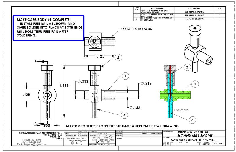
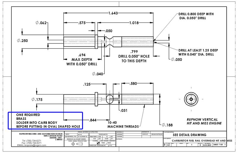
ElGringo--After the tube is soldered into the carb body, set the carb body up in your milling machine vice and after picking up the center of the main air passage in the carb body use an endmill of the specified size, plunge cut a circular hole thru the tube . Then just offset the spindle in one direction and plunge cut thru again. Then offset in the other direction and plunge thru again. That will give the oval hole.---Brian
hR7Un5.jpg

WaaAfq.jpg
 
Last edited:
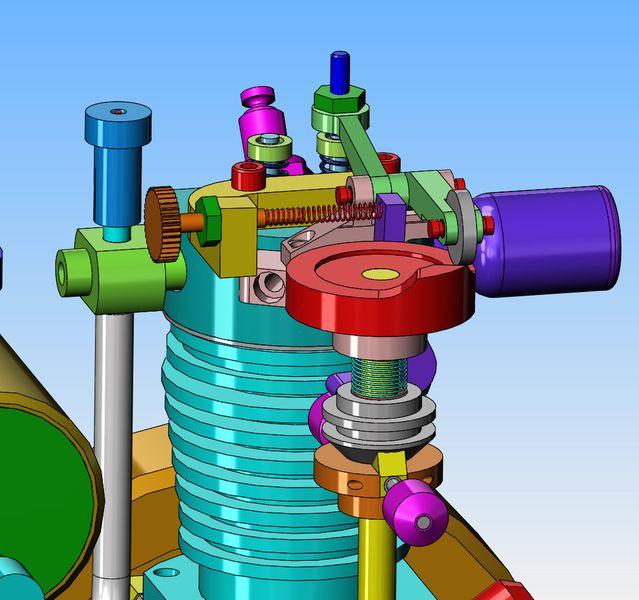
I'm in thinking cap mode this afternoon. As the engine sets right now, there are only two ways to adjust the speed at which the engine kicks in and out of "hit and miss" mode. One is by changing the weight of the governor balls, and the other is by changing the strength of that light green spring on the vertical cam shaft. I think the governor balls are very close to the correct weight right now. The light green spring is a real pig to change, requiring almost complete disassembly of the cam shaft and brackets. However--If I were to add a third factor into this, I believe I could fine tune the kicking in and out of "hit and miss" mode. The way the engine works right now is that once the engine reaches a certain speed, centrifugal force makes the balls fly outward away from the cam-shaft (as it is shown in the model). The cams on top of the governor arms force the grey governor thimble upwards, compressing the light green spring and in turn makes the dark blue "hit and miss lever" rotate and end up underneath the rocker arm, which prevents the exhaust valve from closing. It works great, but I have no control over when this happens. If I were to make the yellow bracket which bolts in place with two of the head bolts, then I could tap a hole in it, and add the bronze colored adjustment screw and lock nut. The spring from a ball point pen would be Loctited to the bronze threaded adjustment screw, and the other end would bear against the dark blue "hit and miss lever". Any pressure applied to the "hit and miss lever" by the spring would counteract the force applied by the light green governor spring. This should give me the ability to fine tune the rpm at which the engine kicks in and out of "hit and miss" mode.
G7fhM5.jpg
 
Here she is boys, my mother 99 years old today. That handsome (slimmer) fellow with her is myself, turned 73 in July. Drove up north and had a little birthday party at the senior citizens manor where she lives. Good time was had by all, my back is sore--driving 400 kilometres will do that.
TBh4BP.jpg
well happy birthday and many more my mom is 99 and will be 100 april 12.
 
Back
Top