Tiny Inline 4 Cylinder IC
- Thread starter kcmillin
- Start date

Help Support Home Model Engine Machinist Forum:
This site may earn a commission from merchant affiliate
links, including eBay, Amazon, and others.
- Joined
- Jan 19, 2010
- Messages
- 1,193
- Reaction score
- 41
Alexandre, I am still thinking everything through. I have been busy in the shop on other projects though. I hope to get back to this soon, I still have quite a bit of design work to get everything in place, and some significant parts to be made.
I am currently doing an extensive search for a CNC solution. Alot to grasp the old noggin around there. I am about to go mad trying to decide on what to do.
Kel
I am currently doing an extensive search for a CNC solution. Alot to grasp the old noggin around there. I am about to go mad trying to decide on what to do.
Kel
- Joined
- Jan 19, 2010
- Messages
- 1,193
- Reaction score
- 41
UPDATE:
Milestone achieved.
Been working on the crankshaft this past weekend.
Started Saturday morning off with some milling to get the blank to size, after three crank journals things were going great until BAM pretzel time. So I quietly shut down the shop, went upstairs to contemplate what went wrong. Still not sure as everything was identical with the previous two, so I brushed it off as a fluke.
Sunday came, I decided to have another crack at it. This time was much better and I managed to make the entire crank.
Now the moment of truth. I checked it with a DTI and the three middle main journals were 5 thou out, and the end mains were 2 out.
So, I managed to screw it up again, but this time much less. So I tried to fix it.
I mounted it between centers on the lathe again and decreased the journals size from .250 - .240". Not much different, this would mean that I would now have to bore a bushing instead of using a reamer, but that is no big deal.
So again, the moment of truth, I checked it and all the journals are now within .001 TIR. Good enough for me.
Now that I have finished what is probably the most difficult single part of the engine, I am getting the motivation back to finish the little guy. I am also considering changing the bore from .375" - .5" but am not too sure yet. This would almost double the displacement and give me a square bore and stroke. (a little secret for those who read, I have made two of each part so far, except the crankshaft. So I can use the second block to experiment with a bigger bore. I also have 16 valves and rocker arms, 20 some keepers, and a bunch of springs.)
Also, I tested the distributor and it indeed 'distributes' the spark without any stray sparks. Horray!!!! I was worried about it for awhile.
A few more worries.
The Head. The ports are quite small, .094", but I have no room for bigger holes, so I might end up redesigning the head to 1/2" thick instead of 3/8"
Thanks for lookin in. Now I suppose I should get to work figuring out the camshaft design and mapping out a machining chart.
Kel

$39.99
$49.99
Sunnytech Low Temperature Stirling Engine Motor Steam Heat Education Model Toy Kit For mechanical skills (LT001)
stirlingtechonline

$54.46
Amana Tool - 46280 CNC 2D & 3D Carving 6.2 Deg Tapered Angle Ball Tip x 1/32 Dia x 1/64
Express Tool Supply
![DreamPlan Home Design and Landscaping Software Free for Windows [PC Download]](https://m.media-amazon.com/images/I/51kvZH2dVLL._SL500_.jpg)
$0.00
DreamPlan Home Design and Landscaping Software Free for Windows [PC Download]
Amazon.com Services LLC
$99.90
$109.90
5PCS/Lot ISO30 ER32-60 Balance Collet Chuck G2.5 30000rpm CNC Tool Holder Stainless Steel Nickel plated With Pull Stud Woodworking Machine
david PA system

$38.26
$49.99
Becker CAD 12 3D - professional CAD software for 2D + 3D design and modelling - for 3 PCs - 100% compatible with AutoCAD
momox Shop

$519.19
$699.00
FoxAlien Masuter Pro CNC Router Machine, Upgraded 3-Axis Engraving All-Metal Milling Machine for Wood Acrylic MDF Nylon Carving Cutting
FoxAlien Official

$53.00
$59.99
Keetopteep Hot Air Stirling Engine Motor Education Model Electricity Power Generator LED Lights Kit Teaching Stirling Engine Kit for Adults Desktop Educational Toy Gift for Engineers (KTP01)
wanrongxianzhisuojiatingnongchang

$443.98
TM NEXDYNAMI AT29618 Water Pump Compatible With/Replacement For John Deere 1020 1520 2020 300 301 400 401 440 440A 480 AT29618
VIVID MARKET CORPORATION
Lakc
Well-Known Member
Way to go Kel, crankshafts are the hardest part.
- Joined
- Jan 19, 2010
- Messages
- 1,193
- Reaction score
- 41
Thanks for the comments guys.
I have been working on this motor quite a bit recently.
I was not able to get many 'in process' shots of a few of the parts, but I just copied what I seen on this website.
All I had left to build was
connecting rods and pistons.
The bushings for the crank.
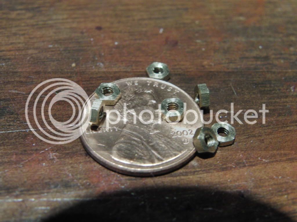
Some really tiny nuts for the valve adjustment.
Pushrods
Intake manifold
I still have yet to make
a carb,
water pump and radiator
a stand
But................................IT RUNS!!!!! IT RUNS!!!!!!! IT RUNS!!!!!!!!!
I just had to get her on the test stand (vise) and see if I could get her to pop. It took some tweaking, and I still don't think I am running on all cylinders, but I am getting about 5-6000 rpm out of her before I shut her down. EXCITED I AM
I think the neighbors are wondering what is happening, I yelled at the top of my lungs WOOOOOOOOOOO HOOOOOOOOOOOOOOOOOOOOOOOOOOOO repeatedly. :big:
I used a carb from the tiny IC I made last year, I really need to get a better carb with a good throttle.
Anyway, I am curently downloading the pics and VIDEO (No, I did not forget to pick up the camera)
More to come!!!
A very Happy,
Kel
- Joined
- Jan 19, 2010
- Messages
- 1,193
- Reaction score
- 41
THanks Ian!
The vid is still uploading.
Here are some pics of the connecting rods and pistons connected to the crank.
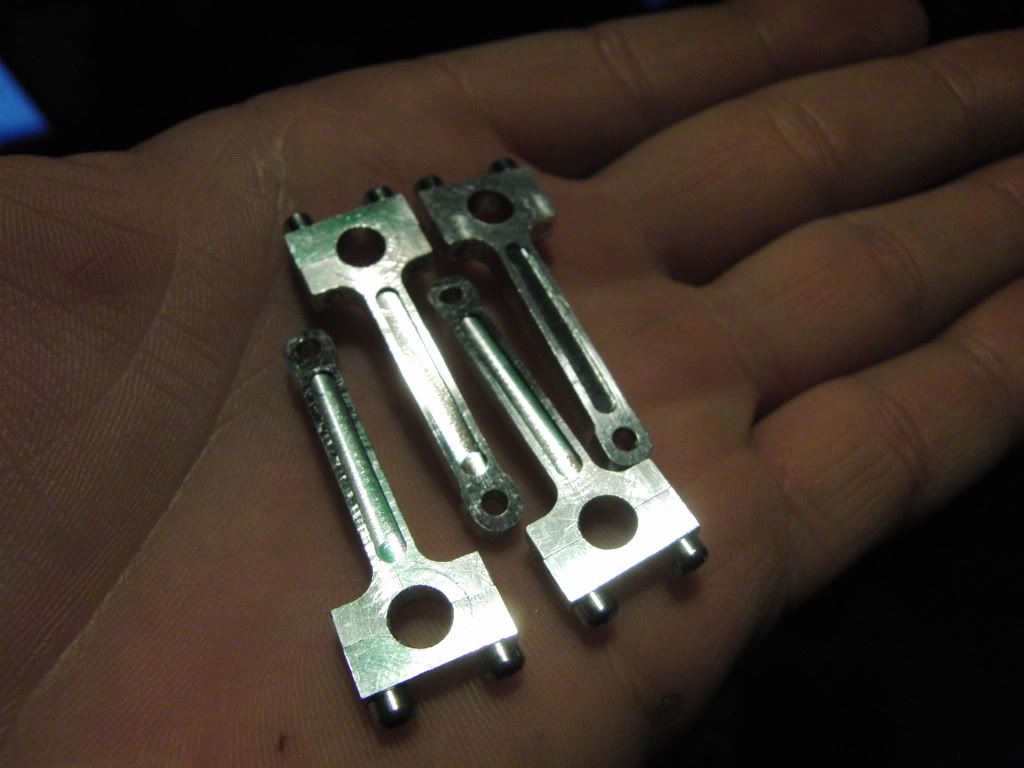
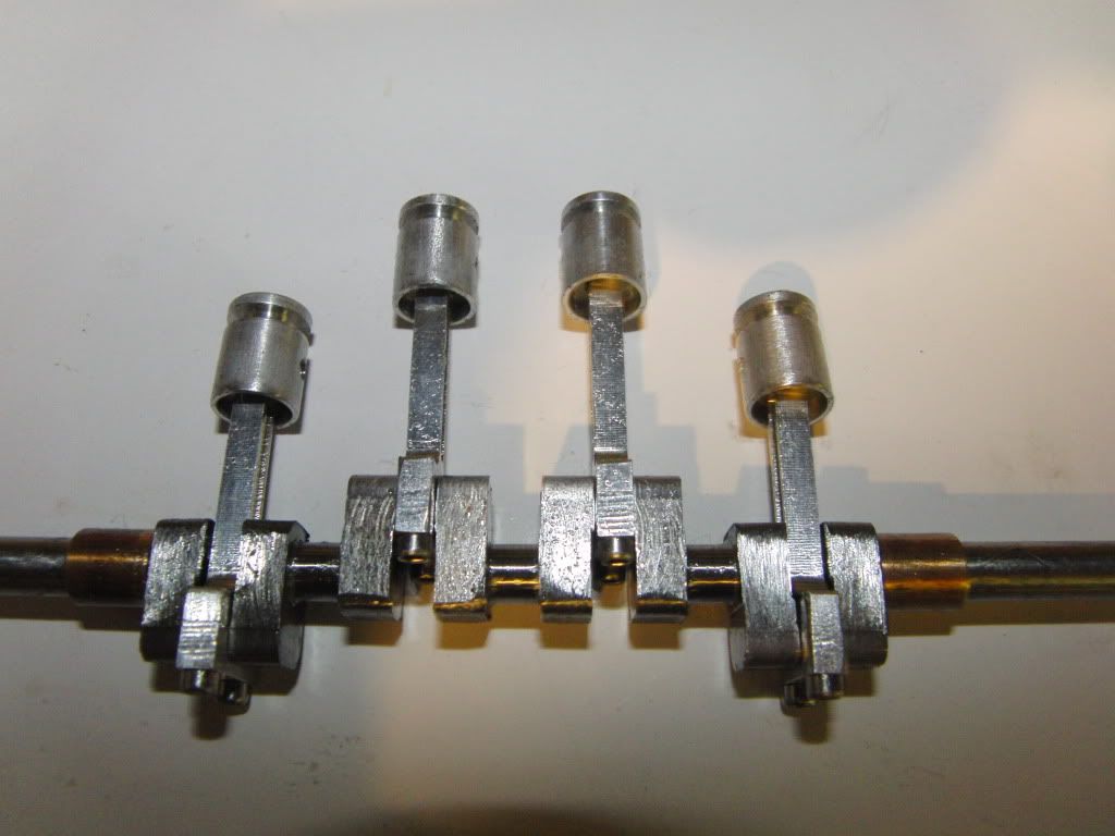
I also forgot to mention I made the Cam. But most of you may have figured it out.
I did manage to photograph the process.
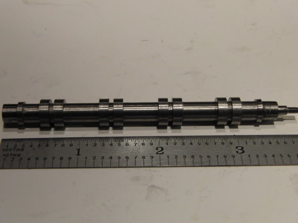
I started with a 3/8" bar of drill rod.
I made it to the correct length and made the threads and register for the gear.
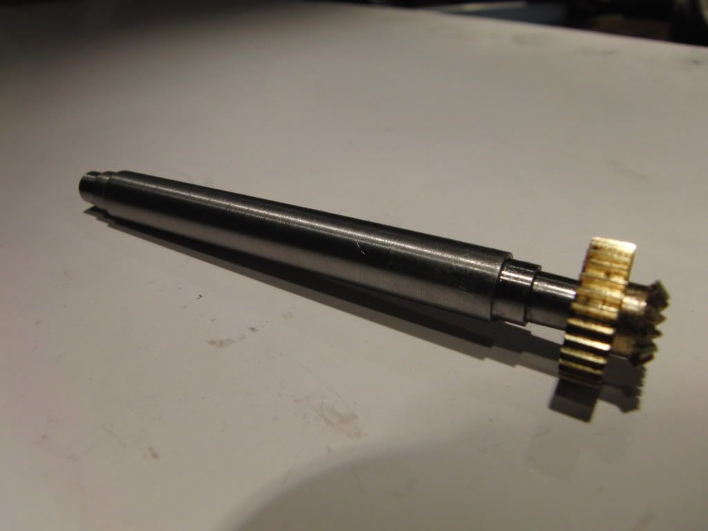
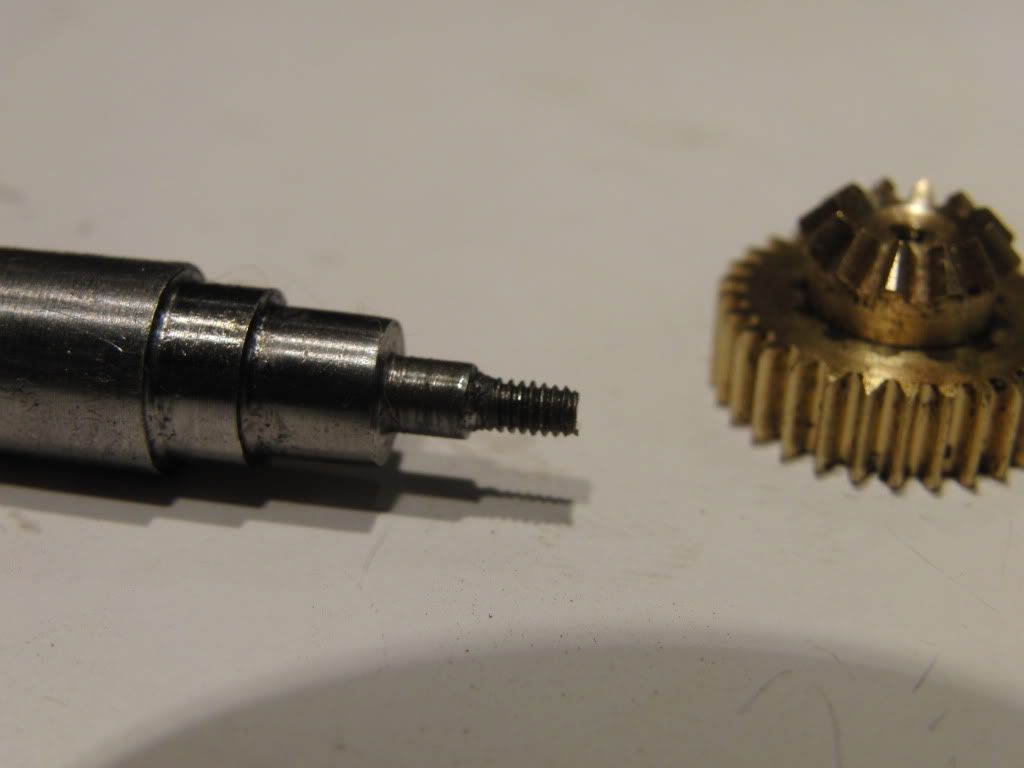
Then I turned out the lobe blanks on the bar.,
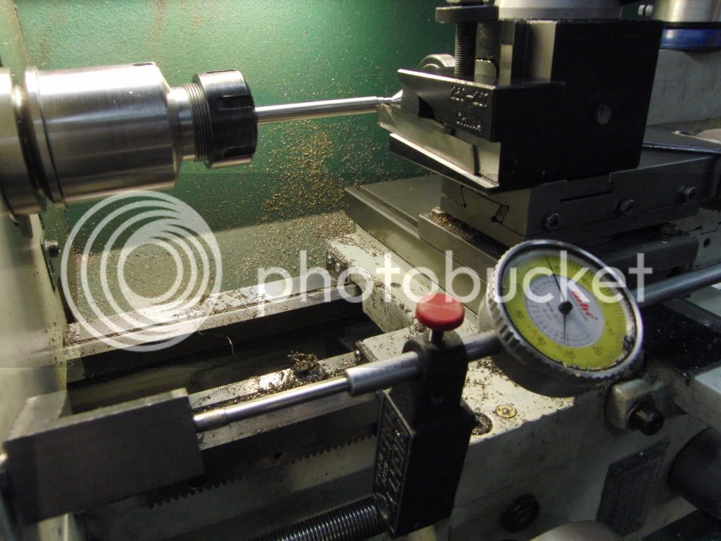
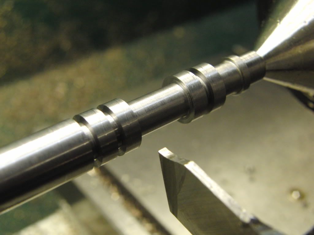
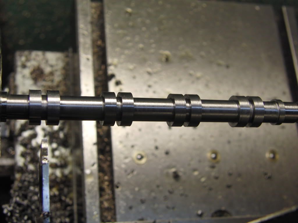
Then it was off to the mill to make the lobes to shape.
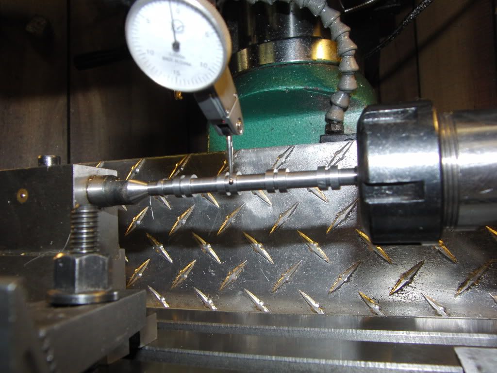
I though I had it all figured out but the number 2 and three cylinders got swapped somewhere along the line. Luckily these two cylinders are in phase. I am not to sure what happed though.
So, I milled both flats on the lobe
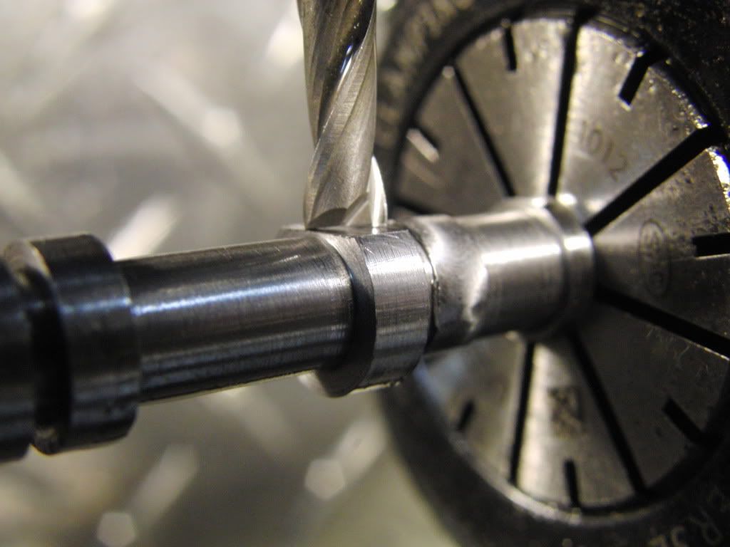
Then I set the cutter on the center line and turned the rotary table. this milled out the bottom side of the lobe, and created the necessary radius.
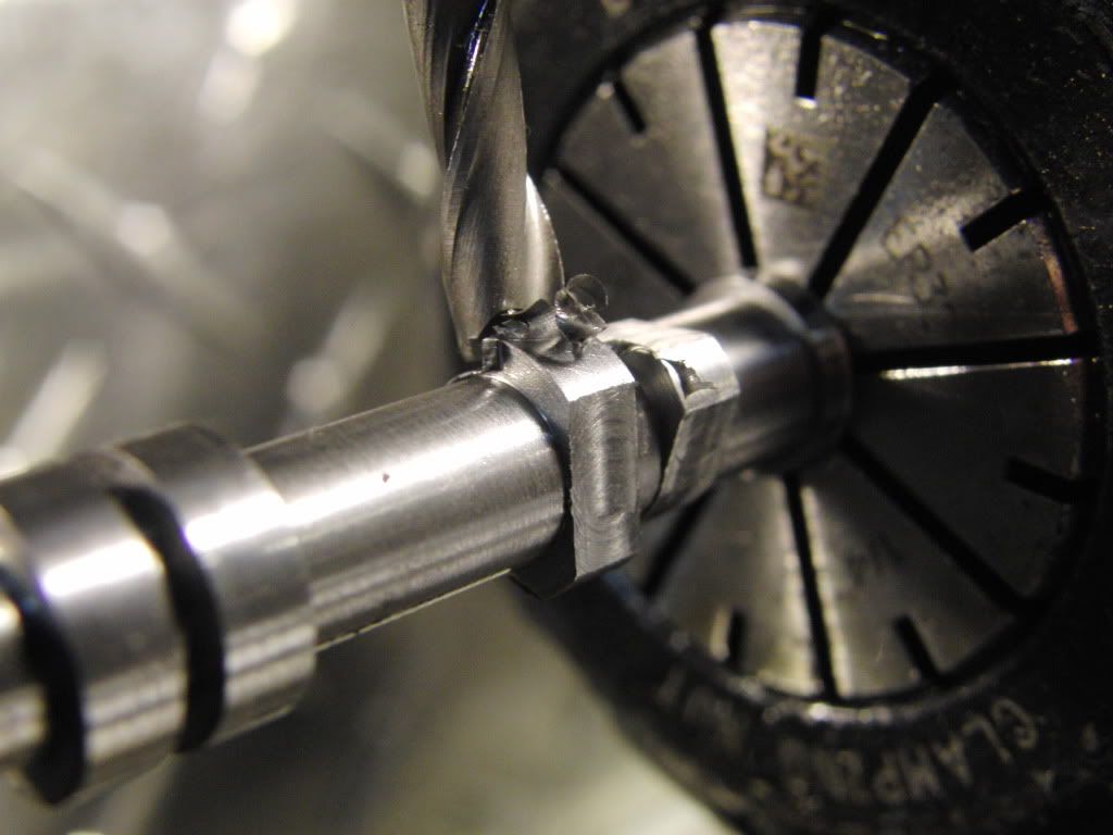
Here it is finished.
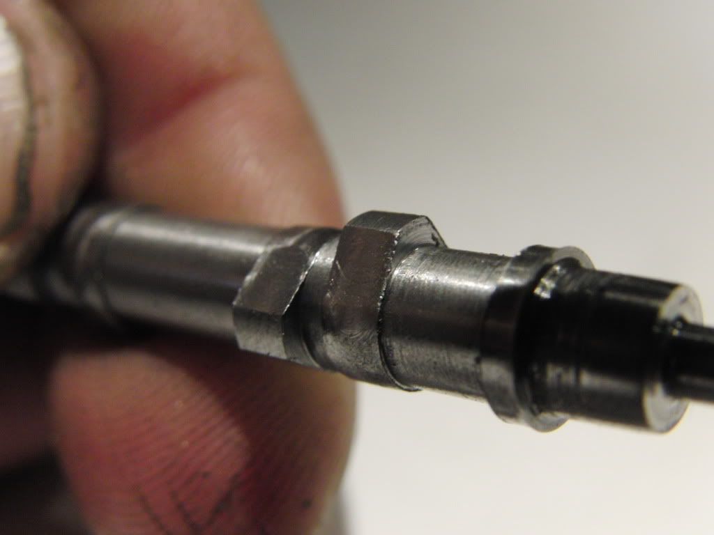
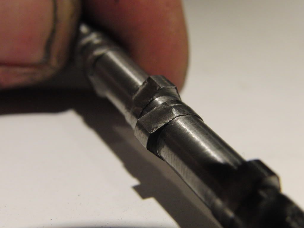
Here are a few more pics.
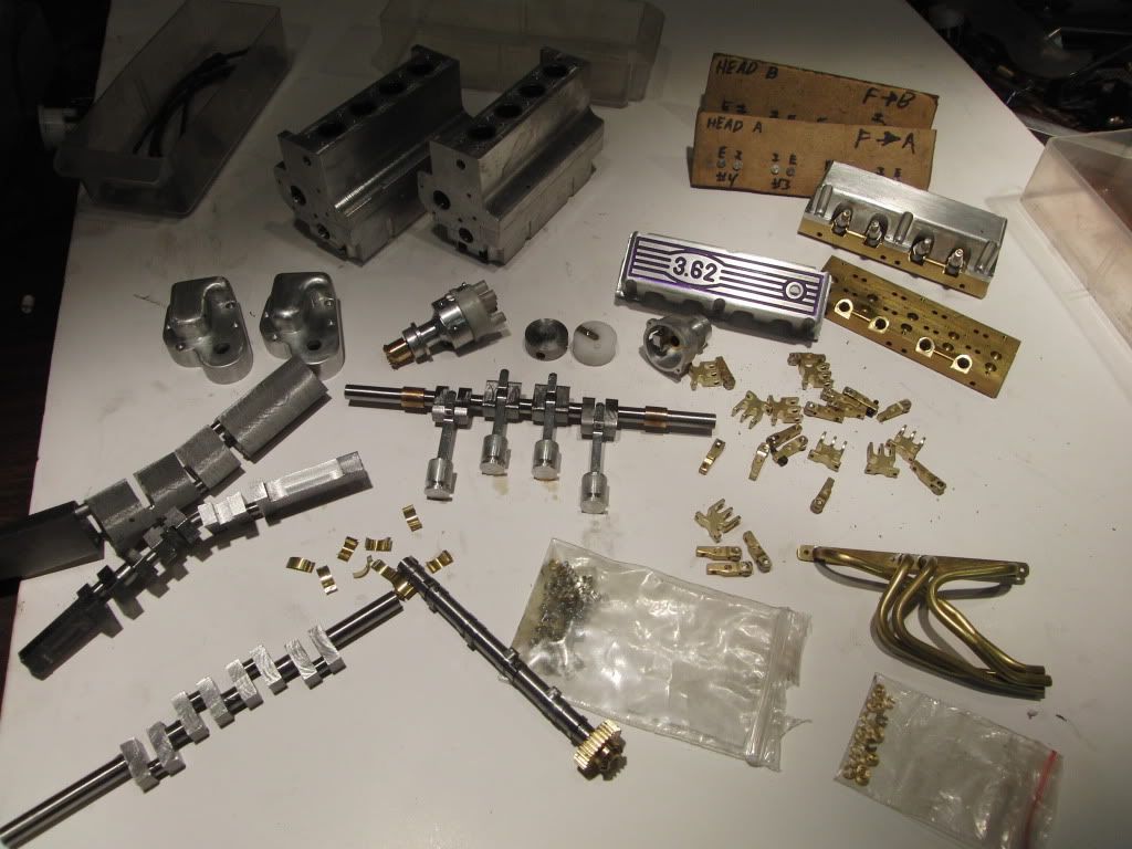
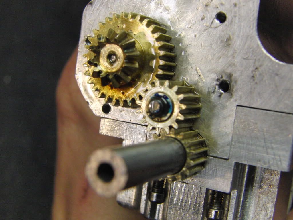
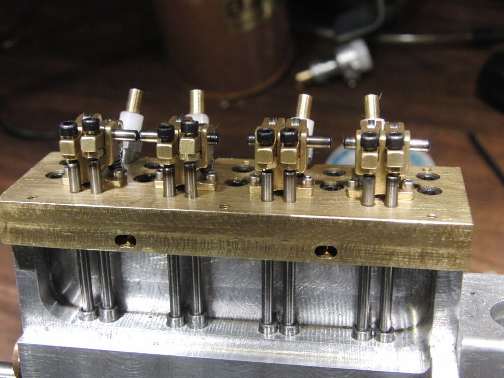
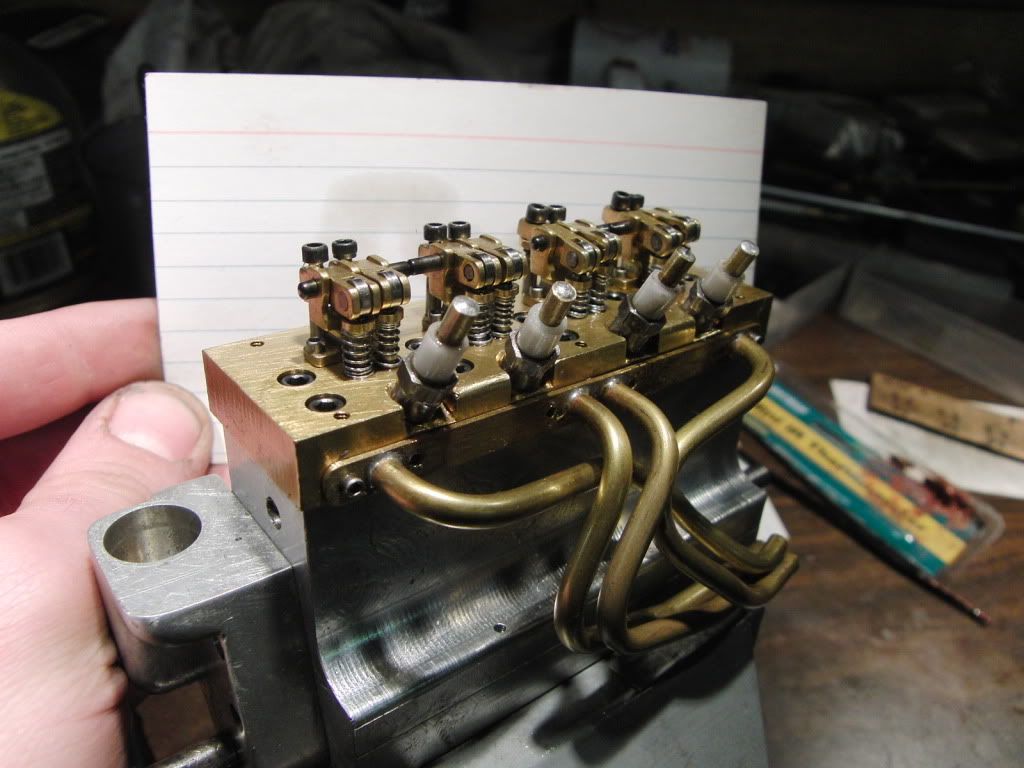
Here are the valve adjustment nuts.
this video sure is taking awhile to upload.
Coming soon though.
Kel
The vid is still uploading.
Here are some pics of the connecting rods and pistons connected to the crank.


I also forgot to mention I made the Cam. But most of you may have figured it out.
I did manage to photograph the process.
I started with a 3/8" bar of drill rod.
I made it to the correct length and made the threads and register for the gear.


Then I turned out the lobe blanks on the bar.,


Then it was off to the mill to make the lobes to shape.

I though I had it all figured out but the number 2 and three cylinders got swapped somewhere along the line. Luckily these two cylinders are in phase. I am not to sure what happed though.
So, I milled both flats on the lobe

Then I set the cutter on the center line and turned the rotary table. this milled out the bottom side of the lobe, and created the necessary radius.

Here it is finished.


Here are a few more pics.


Here are the valve adjustment nuts.

this video sure is taking awhile to upload.
Coming soon though.
Kel
- Joined
- Jan 19, 2010
- Messages
- 1,193
- Reaction score
- 41
And the video
<object width="480" height="390"><param name="movie" value="http://www.youtube.com/v/ngaGpyR6v8Q?fs=1&hl=en_US"></param><param name="allowFullScreen" value="true"></param><param name="allowscriptaccess" value="always"></param><embed src="http://www.youtube.com/v/ngaGpyR6v8Q?fs=1&hl=en_US" type="application/x-shockwave-flash" allowscriptaccess="always" allowfullscreen="true" width="480" height="390"></embed></object>
Kel
Congratulations!! The little critter really sounds good.
Regards,
Chuck
Regards,
Chuck
Great job man!! I see you like to make more than one like me. Pair of the little buggers would look awesome in a little boat of some kind.
Congrats!!!!!!!!!
Congrats!!!!!!!!!
- Joined
- Jan 19, 2010
- Messages
- 1,193
- Reaction score
- 41
Thanks for the Great Comments guys! It really Means a lot.
Ray, the build of your Tiny IC is what litl the fuse on this project, and provided some necessary information. Thanks you for that.
Steve, I learned it from watching you :big:. The second engine will be bored out to .5". I figure why not, I got the room. I am also contemplating making a turbo, but I think that will do funny things with the small carb.
I plan on tearing down the little guy, cleaning everything up, adjusting the bevel gears, make a new carb, polish the valve stems, and re-lap with jewlers rouge. Among other things.
Thanks again everyone.
Kel
Similar threads
- Replies
- 95
- Views
- 12K


![TurboCAD 2020 Designer [PC Download]](https://m.media-amazon.com/images/I/51UKfAHH1LL._SL500_.jpg)


