Gordon---That sounds very interesting. I will have to try that method.----Brian
You are using an out of date browser. It may not display this or other websites correctly.
You should upgrade or use an alternative browser.
You should upgrade or use an alternative browser.
T head engine by Brian
- Thread starter Brian Rupnow
- Start date

Help Support Home Model Engine Machinist Forum:
This site may earn a commission from merchant affiliate
links, including eBay, Amazon, and others.
Gordon, your method if fine for cams with flat flanks but the other method is needed for radiused flanks or use something like CamCalc if the cam has to be held horizontally ( long multiple cam shaft) as you can only reach down so far with it held vertically.
The method was described in Model Engine Builder and I first used it on the Hoglet cams, now its a doddle on the CNC which also does the nose radius
The method was described in Model Engine Builder and I first used it on the Hoglet cams, now its a doddle on the CNC which also does the nose radius
Great stuff!
I learn such a lot from these discussions.
I learn such a lot from these discussions.
- Joined
- Jan 4, 2011
- Messages
- 1,443
- Reaction score
- 405
First, you poke a hole in one end of the egg, then ...Awake---You're teaching your granny to suck eggs. The axis of the workpiece is vertical.
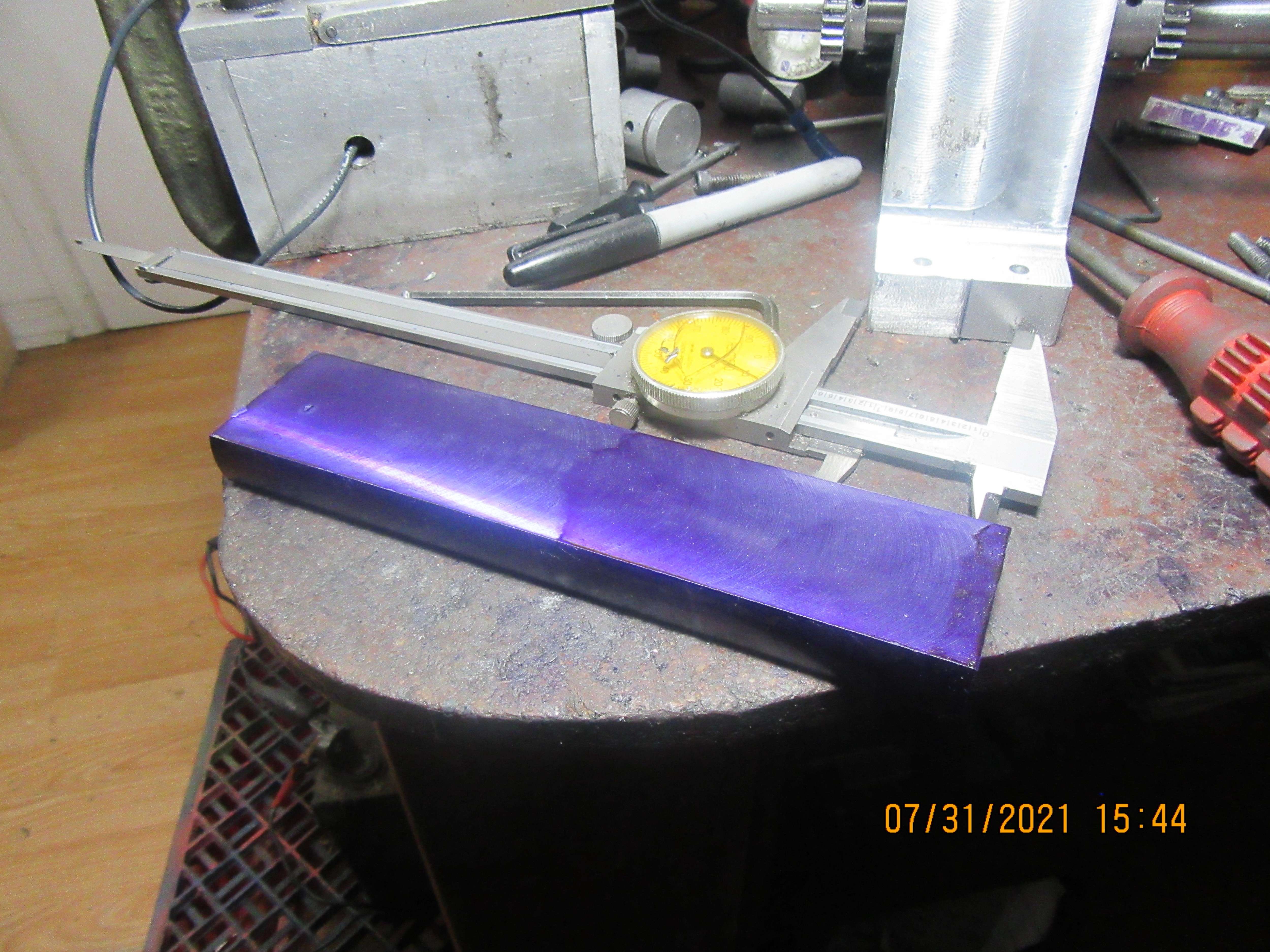
Having a lazy day today. When I was reducing the 1144 roundstock for my crankshaft from round to flat the other day, I noticed that the cut was different in one direction than the other in the X axis. This is a sure indicator of a mill being out of tram. I tore down my set-up and got out the steel brake disc that I use for tramming the mill. Using my coaxial indicator I trammed the mill, then replaced the mill vice and part being worked on. Then I used a 2" face mill to mow away the other side of the round stock, and ended up with a flat bar of 1144 stress proof steel to make a crankshaft from. Not a lot of actual progress, but now I have the material to go ahead and start machining a crankshaft tomorrow.


$171.00
$190.00
Genmitsu CNC 3018-PRO Router Kit GRBL Control 3 Axis Plastic Acrylic PCB PVC Wood Carving Milling Engraving Machine, XYZ Working Area 300x180x45mm
SainSmart Official

$45.99
Sunnytech Mini Hot Air Stirling Engine Motor Model Educational Toy Kits Electricity HA001
stirlingtechonline

$49.95
$55.99
DjuiinoStar Hot Air Stirling Engine Assembly Kit: Spend 30 Minutes to Build Your Own Stirling Engine
djuiinostar

$599.00
$649.00
FoxAlien Masuter Pro CNC Router Machine, Upgraded 3-Axis Engraving All-Metal Milling Machine for Wood Acrylic MDF Nylon Carving Cutting
FoxAlien Official

$38.70
$49.99
Becker CAD 12 3D - professional CAD software for 2D + 3D design and modelling - for 3 PCs - 100% compatible with AutoCAD
momox Shop

$99.99
AHS Outdoor Wood Boiler Yearly Maintenance Kit with Water Treatment - ProTech 300 & Test Kit
Alternative Heating & Supplies

$19.15
$29.95
Competition Engine Building: Advanced Engine Design and Assembly Techniques (Pro Series)
MBC Inc.

$9.99 ($1.00 / Count)
$13.99 ($1.40 / Count)
10 Pcs Carbide Burr Set Bits 1/8" Shank Compatible with Dremel Milwaukee Rotary Grinder Tool Kit Accessories Drill Rasp File Attachment Wood Metal Stone Carve Grind Cut Sand Engrave Polish Porting
SworkerDirect
![DreamPlan Home Design and Landscaping Software Free for Windows [PC Download]](https://m.media-amazon.com/images/I/51kvZH2dVLL._SL500_.jpg)
$0.00
DreamPlan Home Design and Landscaping Software Free for Windows [PC Download]
Amazon.com Services LLC

$26.89
$34.99
Peachtree Woodworking Supply Bowl Sander Tool Kit w/Dual Bearing Head & Hardwood Handle, 42 Pieces Wood Sander Set, 2 Hook & Loop Sanding Disc Sandpaper Assortment, 1/4 Mandrel Bowl Sander
Peachtree Woodworking Supply Inc
I'm about half way done with the crankshaft. So far, so good. I nailed the center diameter right on, and I'm about 0.001 oversize on the one end thats been turned. That last 0.001" will come off with a 220 grit sanding strip. Now I turn the part end for end, put my "lathe dog" on the finished end, and turn the remaining end to 1/2" diameter. I always triple check myself when I'm about to start carving on a crankshaft. I've heard far too many "Cut off the wrong piece" stories, and believe me, it's easy to do.
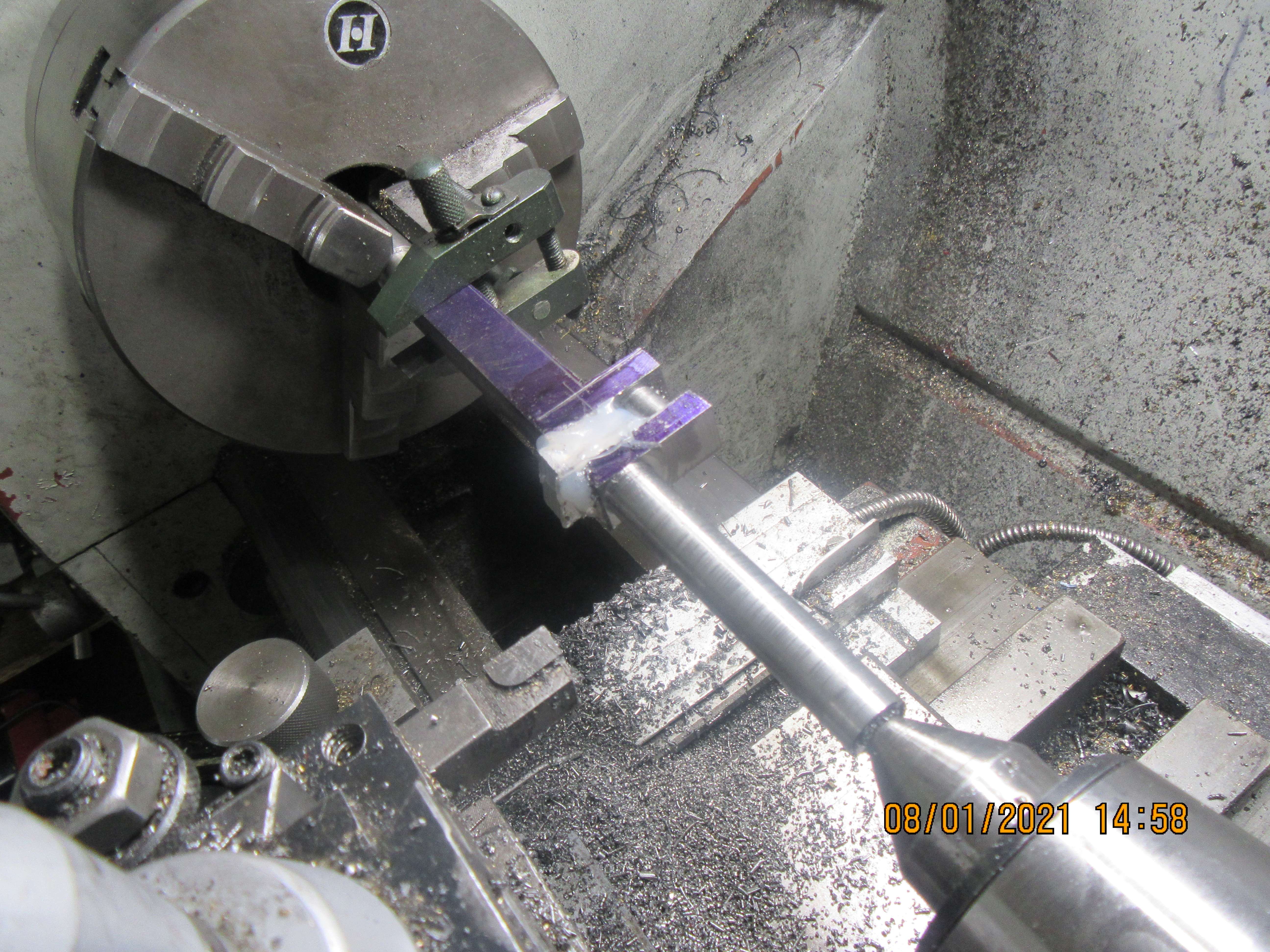

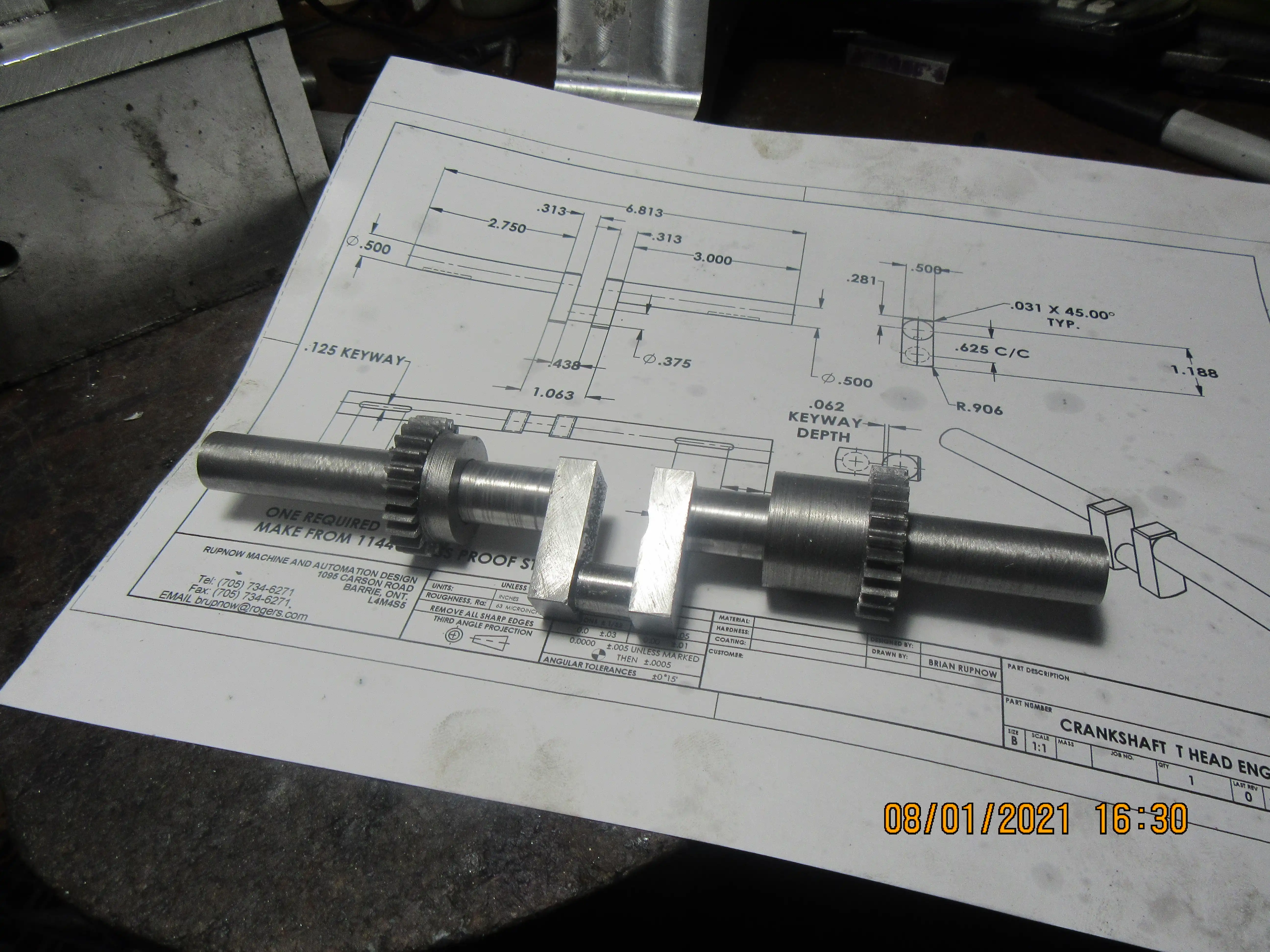
It's suppertime, and I have a finished crankshaft. It needs a couple of keyways, and I will add them tomorrow.

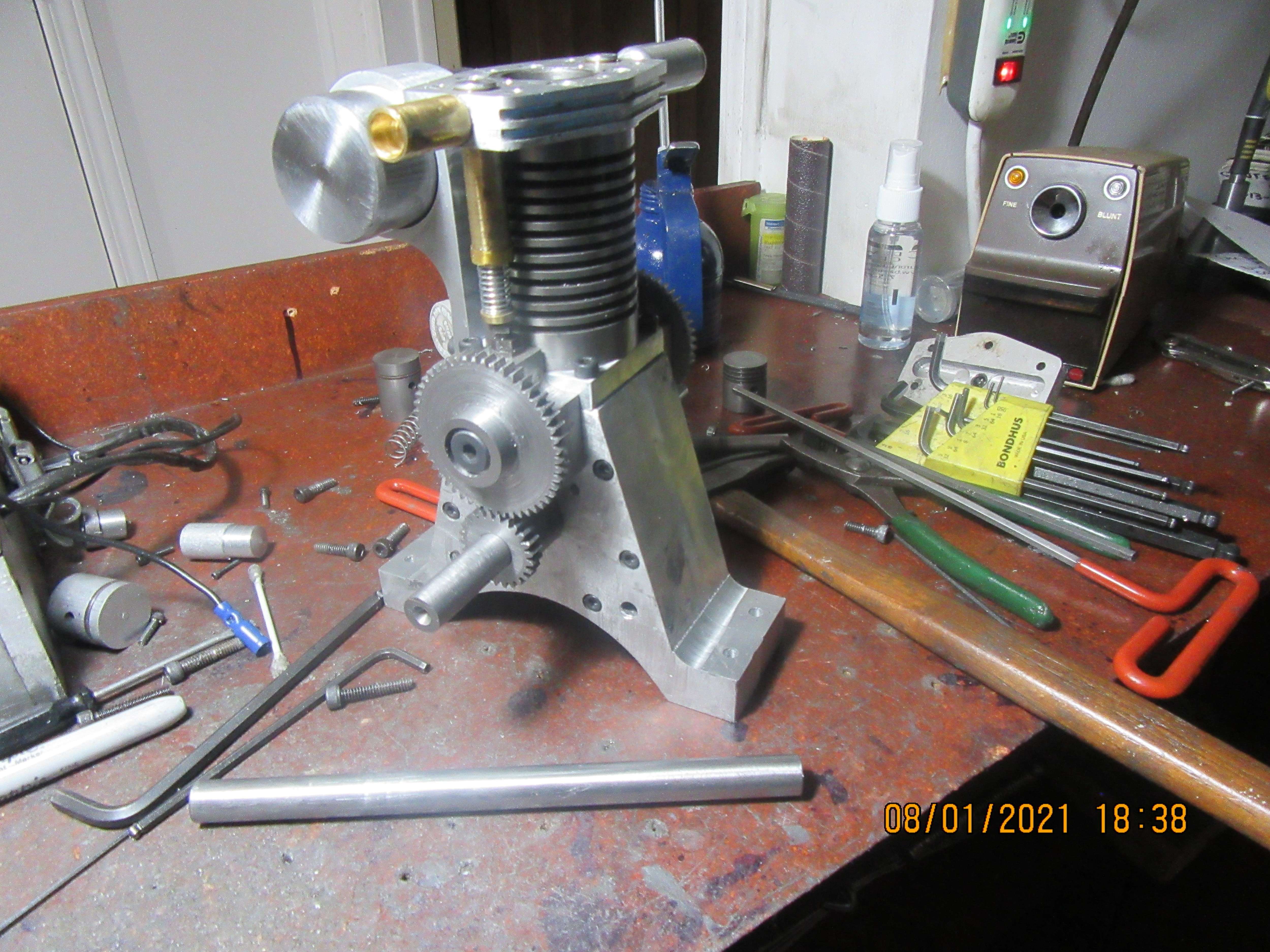
Crankshaft is in, dummy shaft is out. Crankshaft turns easily, nothing crashes. This is always a milestone event for me, because there are so many tolerances that can add up to cause some kind of internal interference with the crankshaft. I'm not going to put keyways in until I'm absolutely sure what I'm doing for flywheels. If I was rich instead of good looking, I'd buy a pair of flywheels, but at $35 each American, plus the difference in our dollars, plus tax, plus shipping, I'd be paying $100 for two flywheels.

Richard Hed
Well-Known Member
- Joined
- Nov 23, 2018
- Messages
- 2,799
- Reaction score
- 757
Geez, Brian, We all know you are good llooking but it's the rich women that DON'T know you are. You need to find one and SHE will pay for it, I'm sure.Crankshaft is in, dummy shaft is out. Crankshaft turns easily, nothing crashes. This is always a milestone event for me, because there are so many tolerances that can add up to cause some kind of internal interference with the crankshaft. I'm not going to put keyways in until I'm absolutely sure what I'm doing for flywheels. If I was rich instead of good looking, I'd buy a pair of flywheels, but at $35 each American, plus the difference in our dollars, plus tax, plus shipping, I'd be paying $100 for two flywheels.

Brian, do you know of a tutorial on making a crankshaft that way?
I've seen bits and pieces but not enough to know how start from a steel bar and end up with a usable part.
I've seen bits and pieces but not enough to know how start from a steel bar and end up with a usable part.
Bob---Here's your tutorial.---Brian
https://www.homemodelenginemachinis...om-1144-stress-proof-steel.33366/#post-363837
https://www.homemodelenginemachinis...om-1144-stress-proof-steel.33366/#post-363837
Richard Hed
Well-Known Member
- Joined
- Nov 23, 2018
- Messages
- 2,799
- Reaction score
- 757
Joe Pie also has a vid on this.Brian, do you know of a tutorial on making a crankshaft that way?
I've seen bits and pieces but not enough to know how start from a steel bar and end up with a usable part.
Bob---Here's your tutorial.---Brian
https://www.homemodelenginemachinis...om-1144-stress-proof-steel.33366/#post-363837
Thanks, Brian!
I sure didn't mean for you to write one today, but it sure seems like you did.
Today I am going to make an aluminum piston. Nothing exotic here, maybe the skirt is a bit longer than usual, but other than that it's a plain old piston. We are going to run cast iron rings on this piston, and this time we are going to make the rings a bit thicker at 0.045" to be an exact match with what George Trimble did in his article on how to make piston rings. The ring radial width will stay at 0.039" same as the rings I made earlier in the summer.
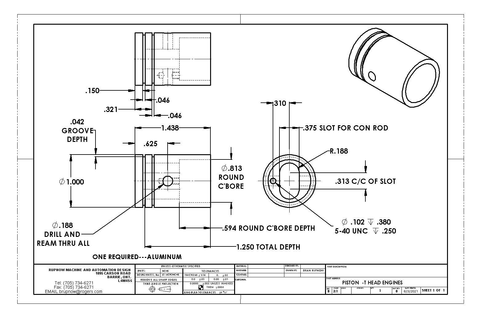

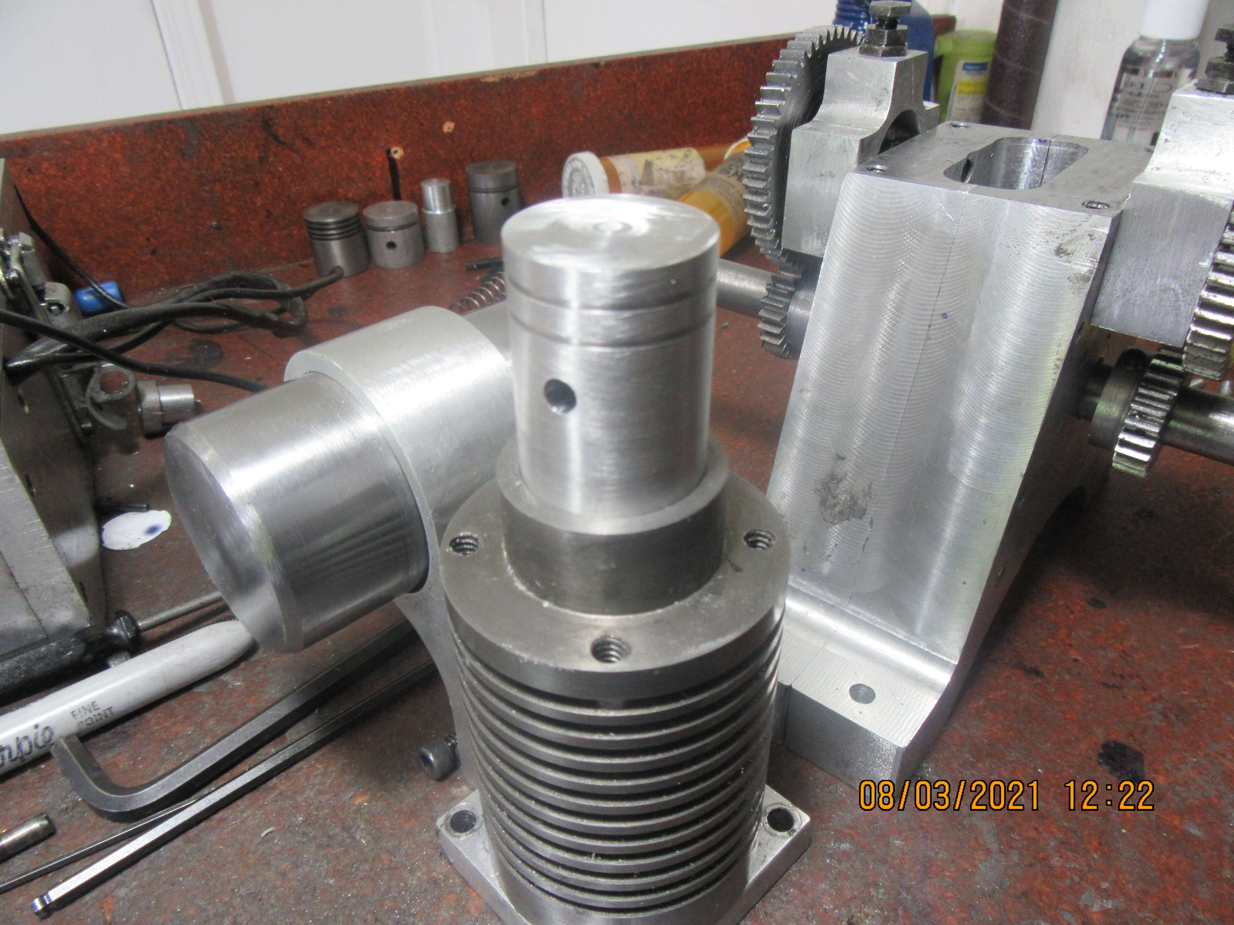
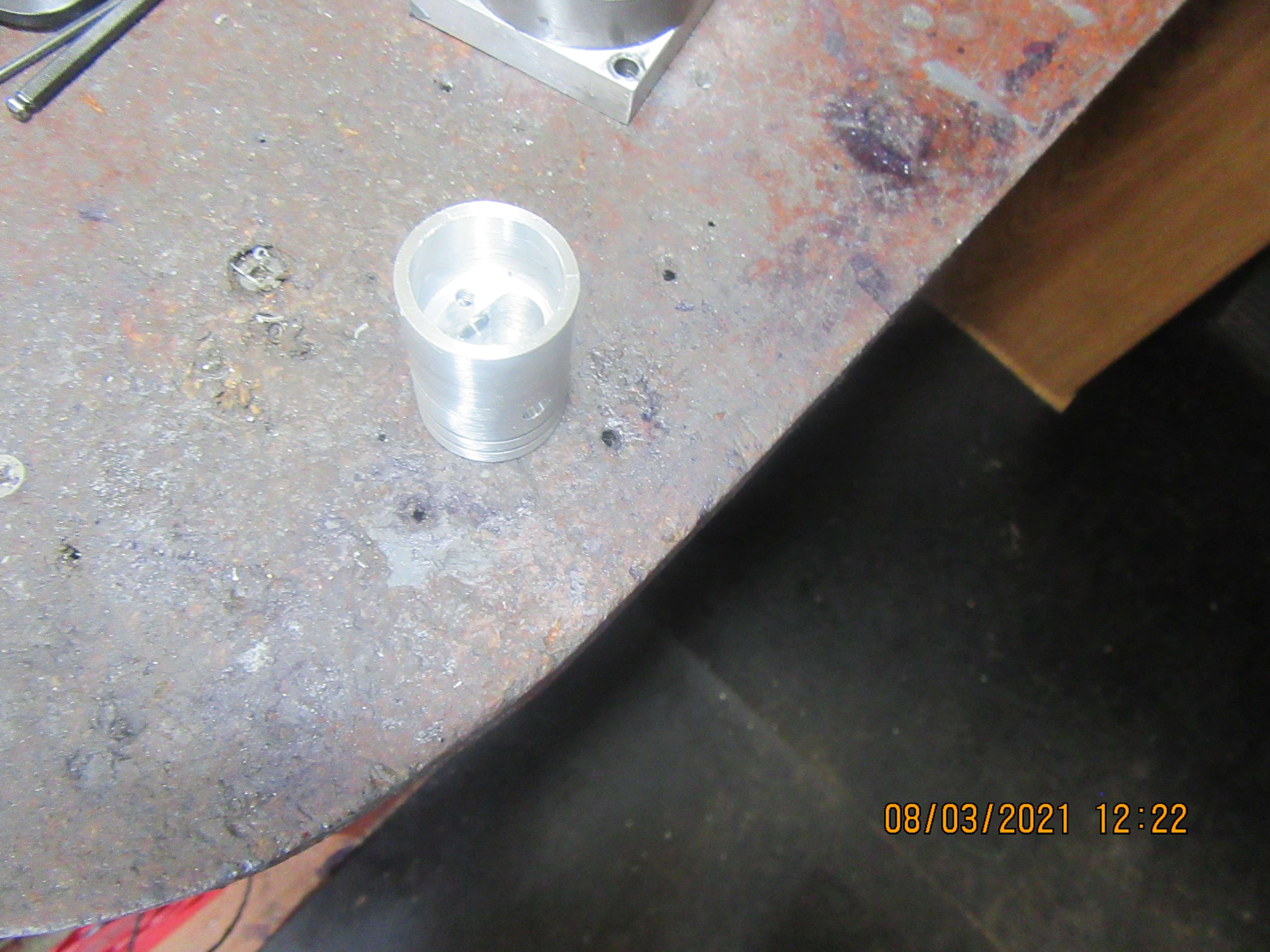
We have a piston!! Everything went well, piston fits cylinder as I had hoped. I almost had a conniption fit when I went to cut the ring grooves. I couldn't find the special cutter that I had ground for me. I looked in all the usual places, and couldn't find it. Then I cleaned up all my work surfaces and I couldn't find it. Then I looked in all the unusual places, and I found it. Now I remember putting it in an unusual place and thinking "Now, I'll keep that separate so I'll know where to find it next time I need it." Growing old gracefully!!!


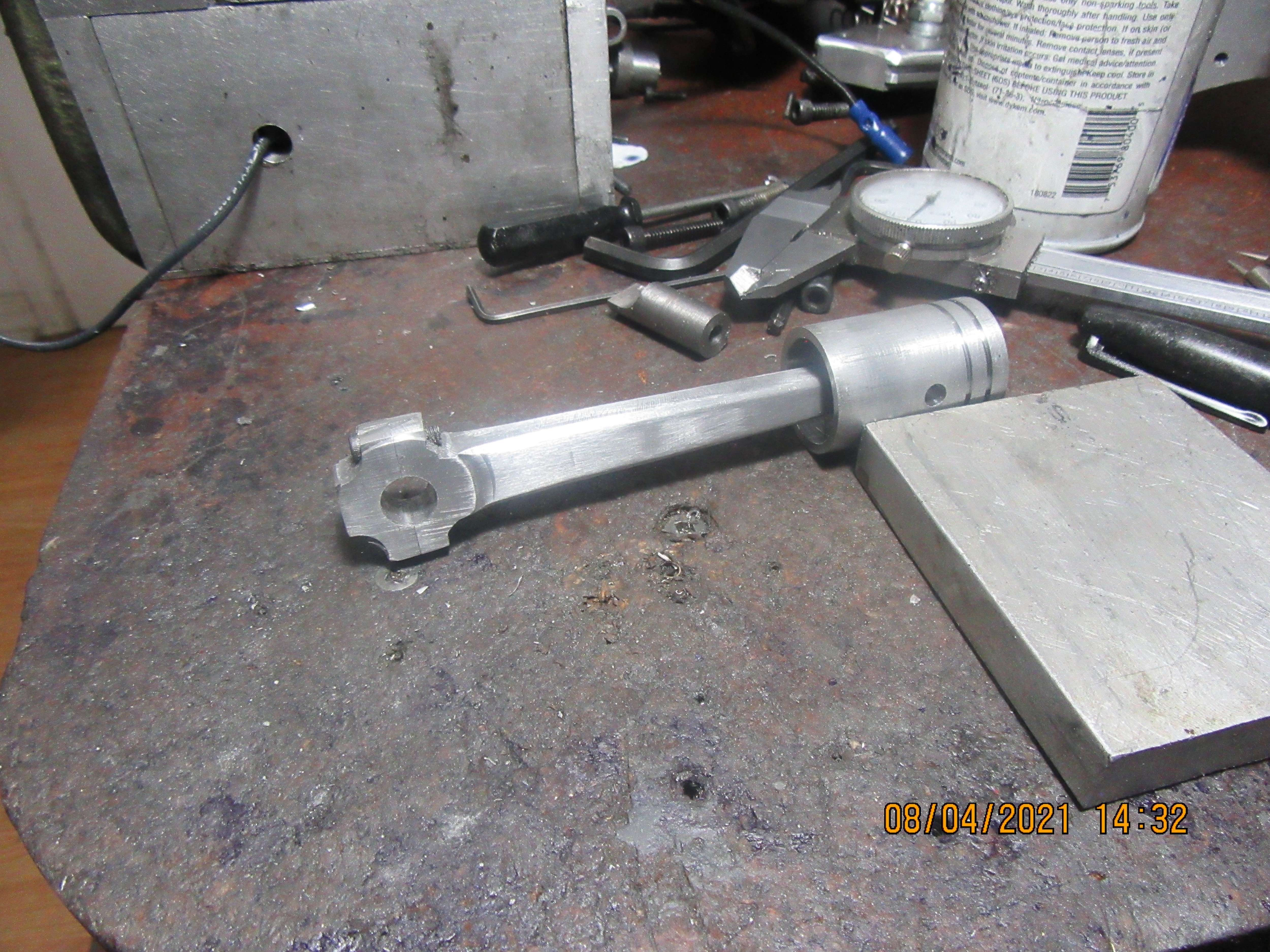
Today was connecting rod day at my house. I don't have much to say about it, but it has eaten up about six hours of my time. It turned out fine. Now I'm going to wash up, then go down to PartSource and pick up a sparkplug, ignition points, and a condenser.

This morning the engine is assembled to check for clearances. Happily, nothing crashes, and the crankshaft can make a full rotation with the connecting rod attached without any clearance issues. This almost completes the major components of the engine, and now it will be a simple matter of installing the cams to complete the valve train. Thanks for having a look.---Brian
Today was ignition points, condenser, and ignition cam day. It also was finish the gas tank day. Everything went as planned. I am going to paint that gas tank and the flywheels, so I probably won't do very much cosmetic work on the brazed joints on the gas filler neck and out-spout. A bit of gloss paint hides a multitude of sins!!
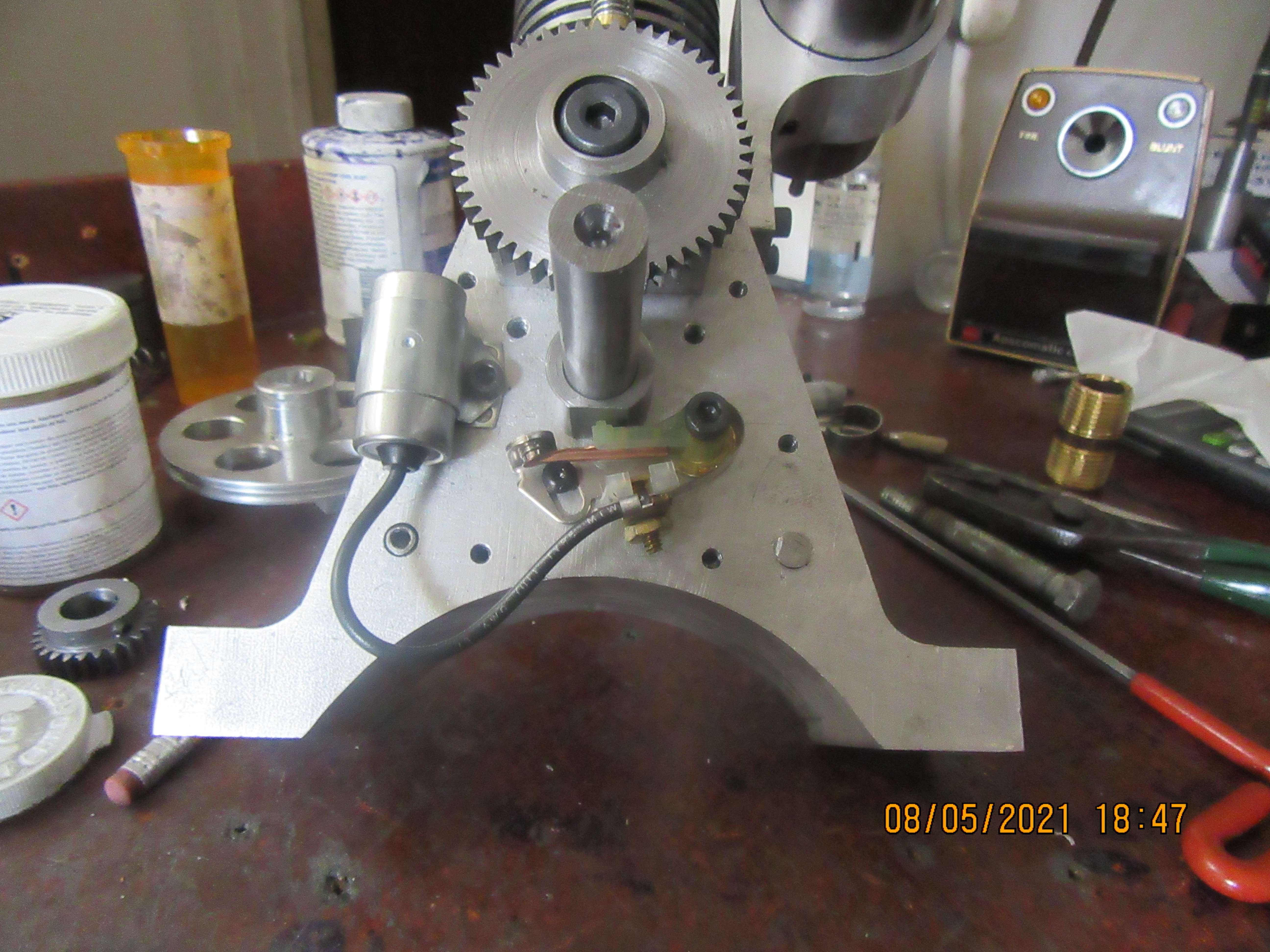
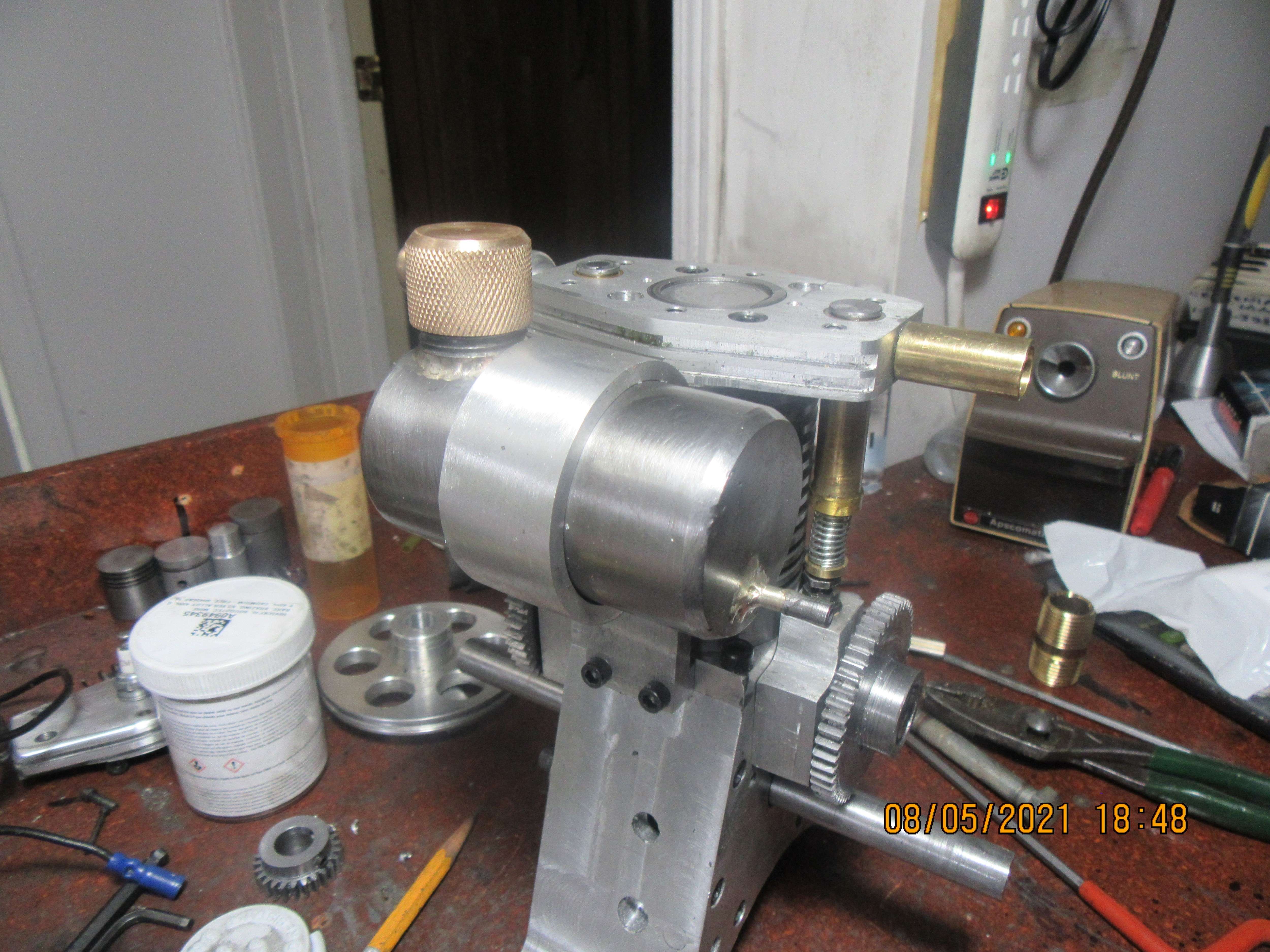


I spent the day working on a real job, but tonight I'm having a close look at this engine. I think that other than the flywheels and gear covers, everything is finished. I'm waiting for my cams to arrive, and there is a bit of finessing to connect the cams to the large gears. I don't need the gear covers to start the engine, so this could get exciting pretty soon. I'm still on the fence regarding the flywheels, but I want to go down to my nut and bolt store and look at something. They have a bin full of casters down there, and I remember seeing some large aluminum casters with rubber bonded to the outer rim. I have some double extra strong schedule 80 pipe here, and if I could machine the rubber off those aluminum casters and put some heavy wall pipe around the aluminum, it might make some nice flywheels.
Similar threads
- Replies
- 11
- Views
- 1K
- Replies
- 413
- Views
- 68K
- Replies
- 148
- Views
- 27K


![MeshMagic 3D Free 3D Modeling Software [Download]](https://m.media-amazon.com/images/I/B1U+p8ewjGS._SL500_.png)


