Gordon---Your very close about the ignition box. It contains a 12 volt coil and an on/off switch, and wire leads which are attached to a 12 volt battery. The points and condenser are mounted on the engine, and there is a cable with an alligator clamp at each end to run from the chassis of the engine down to the negative post on the battery.
You are using an out of date browser. It may not display this or other websites correctly.
You should upgrade or use an alternative browser.
You should upgrade or use an alternative browser.
T head engine by Brian
- Thread starter Brian Rupnow
- Start date

Help Support Home Model Engine Machinist Forum:
This site may earn a commission from merchant affiliate
links, including eBay, Amazon, and others.
- Joined
- Jan 4, 2011
- Messages
- 1,442
- Reaction score
- 403
I have a similar setup except that I have the condenser in the box and a gel battery inside the box. Actually I have two of them. I have a 6v and a 12v. The 6v battery is probably 5+ years old and I will have to change the battery because it will not hold a charge. I also have terminals to provide 6 volts when I use something like a TIM 6 ignition.
- Joined
- Jan 4, 2011
- Messages
- 1,442
- Reaction score
- 403

I have used this idea several times for odd gear teeth. I have had good luck and the plates are not that difficult to make.
When using my rotary table I tend to forget how many turns etc and end up getting to the last tooth and have a gap or cut a partial tooth.
http://oxtool.blogspot.com/2013/11/5c-spindexer-indexer.html
My rotary table has a set of bronze, adjustable "fingers" that are spring loaded against the face of the divider plate. You adjust them to uncover the number of holes that you want that are not a full 360 degrees of rotation. For instance, the 50 tooth gear I just cut was a result of turning the handle on the rotary table one full turn and 16/20 of a second turn. Every time I cut a tooth, I would advance these "sector fingers" so they were up against the engagement pin.--This automatically tells me which hole I must engage with the pin every time I advance the rotary table handle.---This is probably the worst explanation of this process that has ever been written down, but unless I do something really strange, it ensures good gears every time.
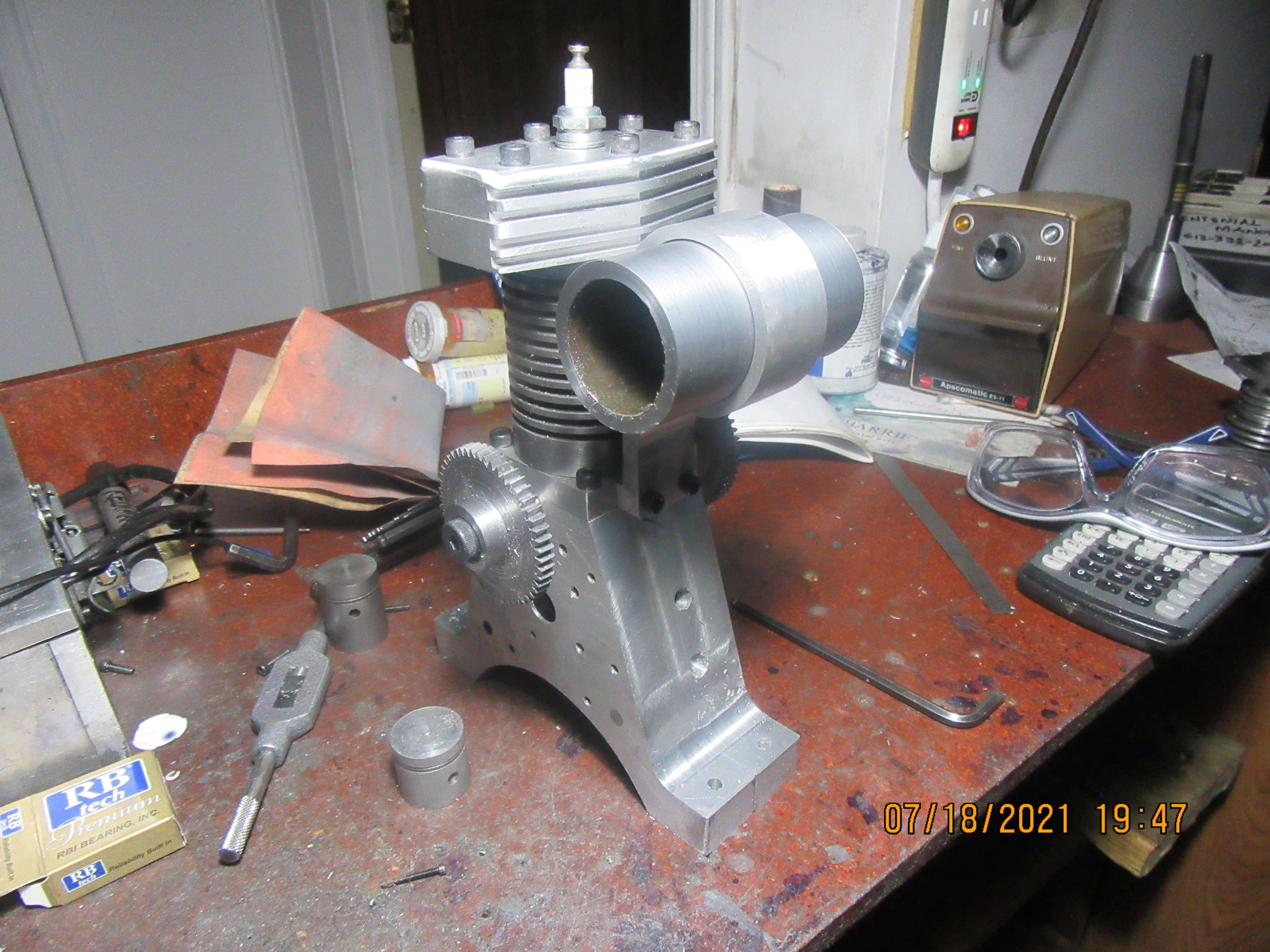
Holy Gas Tank, Batman---Were going to try something a little different. I've made about two dozen gas tanks. Many had the end plates silver soldered in place. A roll of silver solder costs about $100 here. Then I found out that I can J.B. Weld the endplates in and they never leak, but you have to be aware of your construction procedure and have any other soldering or welding finished before you use the J.B. Weld. Tomorrow, I am going to Tig weld the endplates into this tank. Of course there will be a bit of prep work first, probably a counterbore in each end of the pipe, and endplates made with a decent chamfer for the weld to fill. I'll let you know how that turns out.

- Joined
- Feb 17, 2008
- Messages
- 2,330
- Reaction score
- 446
SIRJOHN,
You mentioned cutting bevel gears in a previous post.
Miter, bevel and skew bevel gears can be cut with the same standard involute cutters used for spur gears. They have a different tooth form than the commercial bevel gears that can only be cut by a generating process, but are just as effective. The process is not a lot more difficult than tat for cutting spur gears.
We had a thread on cutting them about 10 years ago. It is at:
https://www.homemodelenginemachinis...utting-with-involute-cutters.9699/post-108419

$45.99
Sunnytech Mini Hot Air Stirling Engine Motor Model Educational Toy Kits Electricity HA001
stirlingtechonline

$599.00
$649.00
FoxAlien Masuter Pro CNC Router Machine, Upgraded 3-Axis Engraving All-Metal Milling Machine for Wood Acrylic MDF Nylon Carving Cutting
FoxAlien Official

$19.15
$29.95
Competition Engine Building: Advanced Engine Design and Assembly Techniques (Pro Series)
MBC Inc.

$99.99
AHS Outdoor Wood Boiler Yearly Maintenance Kit with Water Treatment - ProTech 300 & Test Kit
Alternative Heating & Supplies

$26.89
$34.99
Peachtree Woodworking Supply Bowl Sander Tool Kit w/Dual Bearing Head & Hardwood Handle, 42 Pieces Wood Sander Set, 2 Hook & Loop Sanding Disc Sandpaper Assortment, 1/4 Mandrel Bowl Sander
Peachtree Woodworking Supply Inc

$38.70
$49.99
Becker CAD 12 3D - professional CAD software for 2D + 3D design and modelling - for 3 PCs - 100% compatible with AutoCAD
momox Shop

$171.00
$190.00
Genmitsu CNC 3018-PRO Router Kit GRBL Control 3 Axis Plastic Acrylic PCB PVC Wood Carving Milling Engraving Machine, XYZ Working Area 300x180x45mm
SainSmart Official

$9.99 ($1.00 / Count)
$13.99 ($1.40 / Count)
10 Pcs Carbide Burr Set Bits 1/8" Shank Compatible with Dremel Milwaukee Rotary Grinder Tool Kit Accessories Drill Rasp File Attachment Wood Metal Stone Carve Grind Cut Sand Engrave Polish Porting
SworkerDirect
![DreamPlan Home Design and Landscaping Software Free for Windows [PC Download]](https://m.media-amazon.com/images/I/51kvZH2dVLL._SL500_.jpg)
$0.00
DreamPlan Home Design and Landscaping Software Free for Windows [PC Download]
Amazon.com Services LLC

$49.95
$55.99
DjuiinoStar Hot Air Stirling Engine Assembly Kit: Spend 30 Minutes to Build Your Own Stirling Engine
djuiinostar
Damn, I just lost an entire post.---Here we go again. The tig welding turned out very nice. No, it's not the perfectly overlapping "fish scale" pattern that a professional welder would lay down, but it works for me. A bit of clean-up on the lathe and it should be a beautiful thing. I simply can not afford the $$$ for brass, so I will be painting the gas tank and the flywheels in some complimentary colour.
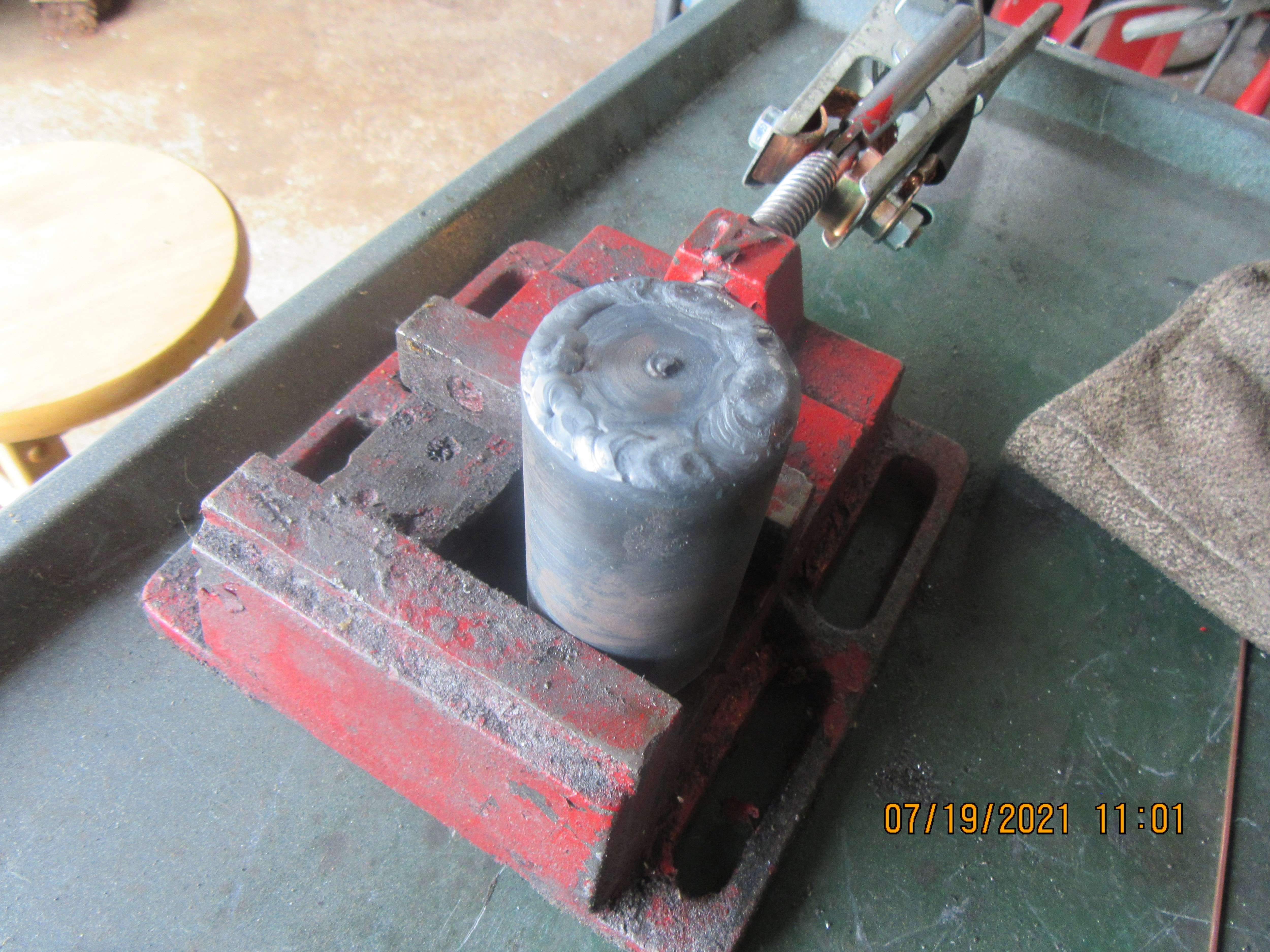
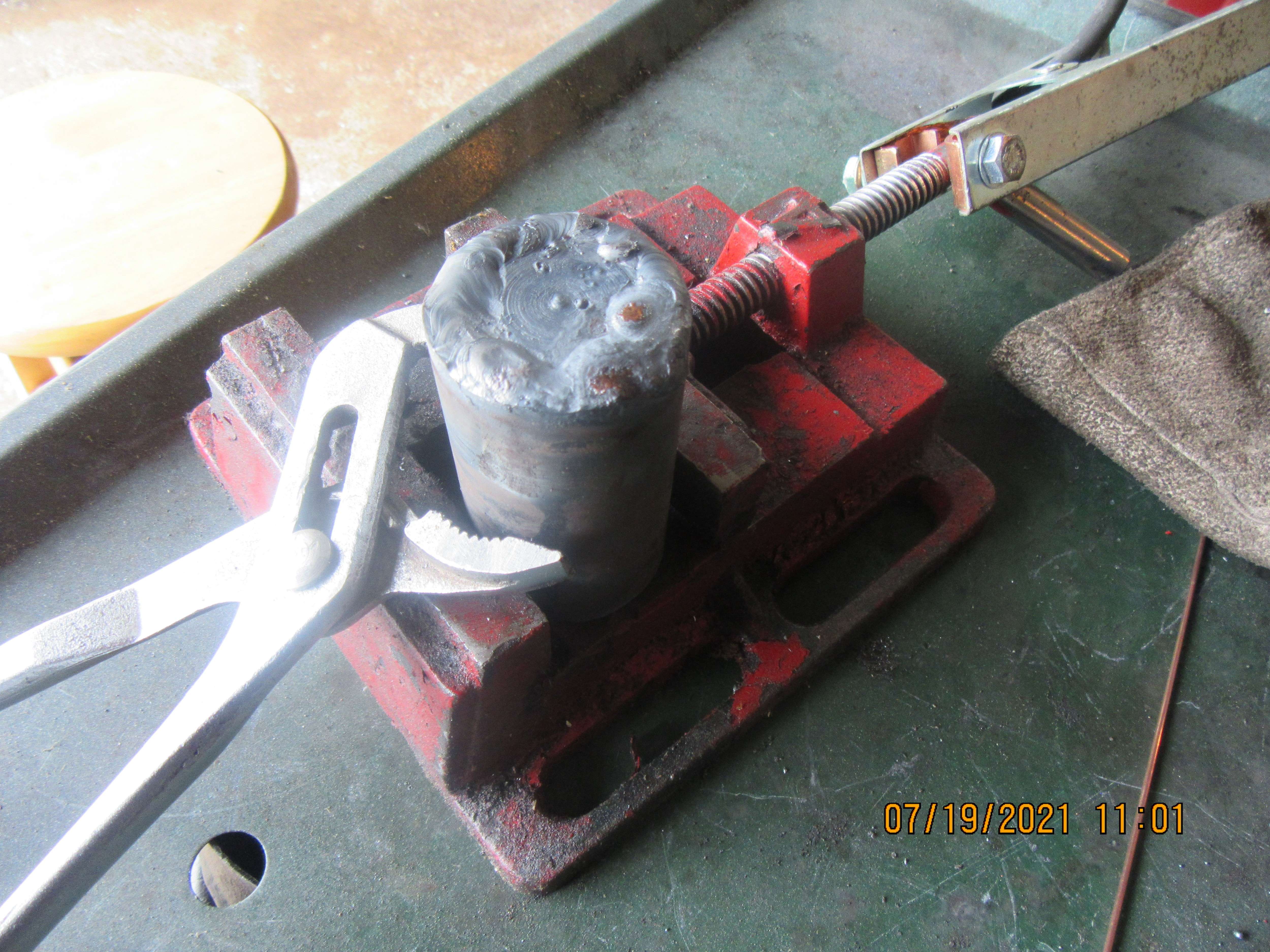


Looks good to me. Keep up the good work.
And it's a lovely thing, what a bit of lathe and file work will do to finish off a welded gas tank.
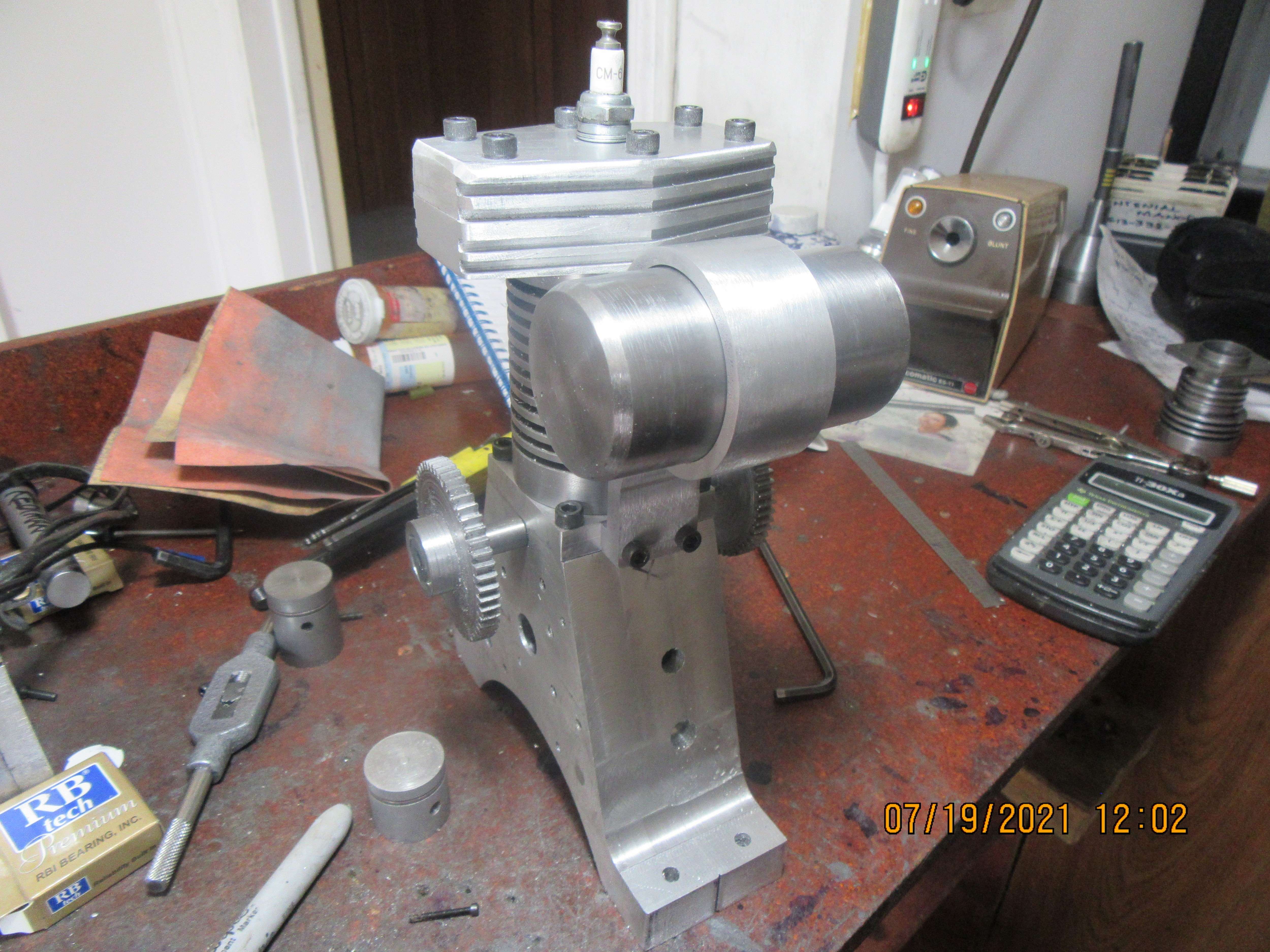

Brian, I made my only gas tank to date as a TIG weldment - works just fine.
That's like a night or day difference in appearance.
That looks like the perfect candidate for some homebrew anodizing.And it's a lovely thing, what a bit of lathe and file work will do to finish off a welded gas tank.

There are many articles and videos online.
The equipment and supplies are trivial and inexpensive.
Rubber gloves and protective glasses highly recommended.
Larry in Rutherford, NJ
My rotary table has a set of bronze, adjustable "fingers" that are spring loaded against the face of the divider plate. You adjust them to uncover the number of holes that you want that are not a full 360 degrees of rotation. For instance, the 50 tooth gear I just cut was a result of turning the handle on the rotary table one full turn and 16/20 of a second turn. Every time I cut a tooth, I would advance these "sector fingers" so they were up against the engagement pin.--This automatically tells me which hole I must engage with the pin every time I advance the rotary table handle.---This is probably the worst explanation of this process that has ever been written down, but unless I do something really strange, it ensures good gears every time.
A corollary to "the worst explanation" is that you CANNOT use your common calculator to determine the correct number of turns and holes.
You MUST use proper fractions.
Ask your kids in elementary school for help, as long as they don't yet allow calculators in class.
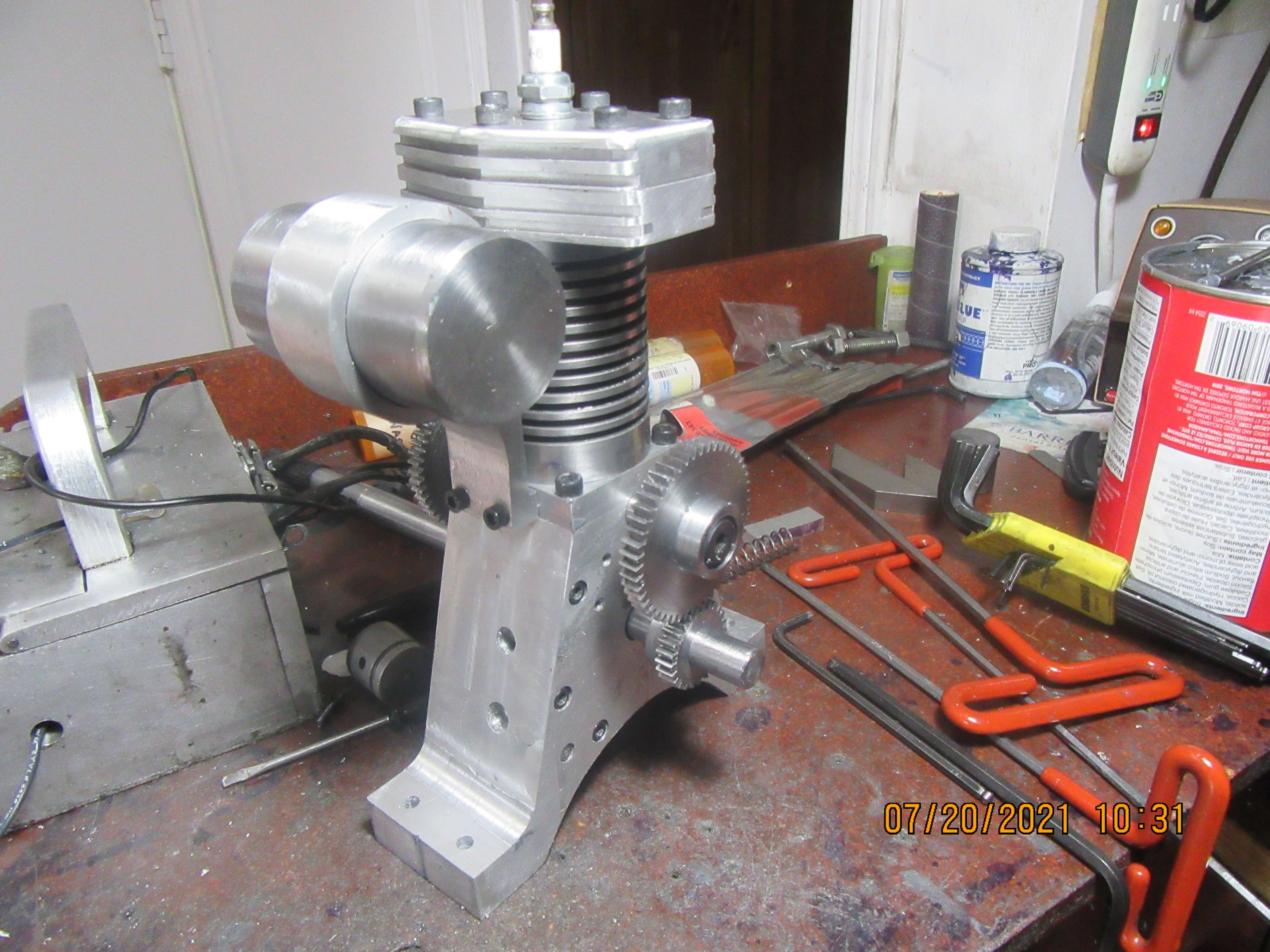
The outer diameter of the crankshaft bearings have been coated with J.B. Weld and located in their bores. Before it has had any chance to set-up, a 1/2" diameter cold rolled shaft has been ran thru both bearings, and the two halves of the crankcase have been reassembled with locating pins and bolts. The two 25 tooth gears were finished this morning and then slid over the ends of the shaft to make sure that they mounted and meshed properly with the camshaft gears.---They do!!!

- Joined
- Jan 4, 2011
- Messages
- 1,442
- Reaction score
- 403
I just ordered a set of three plates for my rotary table. Is there a chart available which would give settings or some type of calculator or a formula? So far I have not found anything. I can find some for 40 turn tables but mine is 90 turn.A corollary to "the worst explanation" is that you CANNOT use your common calculator to determine the correct number of turns and holes.
You MUST use proper fractions.
Ask your kids in elementary school for help, as long as they don't yet allow calculators in class.
I just ordered a set of three plates for my rotary table. Is there a chart available which would give settings or some type of calculator or a formula? So far I have not found anything. I can find some for 40 turn tables but mine is 90 turn.
The formula is fairly straightforward. Here's how to derive it: For a gear with N teeth, you need your table to rotate 1/N revolution each time. Meanwhile, it requires 90 turns of the input handle to achieve 1 revolution of the table (this is for your 90-turn table - change 90 to 40 or 60 or whatever the ratio is for any given table). Thus, you need to turn the input handle 90 / N turns each time. Work this out as a simplified fraction, as was noted above.
Example: You want to make a 48 gear tooth on your 90-turn table. You need to turn the input handle 90 / 48 times per tooth.
90 / 48 = 1 + 42 / 48 turns = 1 + 7 / 8 turns (simplify the fraction), so 1 complete revolution of the input handle plus 7 / 8 of a complete revolution. Do you have a division plate with 8 holes? No? How about something with a multiple of 8, maybe 16 or 24? Let's say you have a 16-hole plate. 16 x 7/8 = 14. So the final answer is, for each tooth, you need to turn 1 + 14 / 16 revolutions. To accomplish that, you will set the sector arms to expose 14 + 1 holes - 1 for the pin to start in, and 14 more for the fractional turn. Turn the input handle until you can drop the pin in the first hole exposed by the sector arms. Take your first cut. Now turn the input handle one complete revolution and then turn it further until the pin drops in the last hole exposed by the sector arms. Move the sector arm assembly so that this hole is now the first hole exposed. Make your next cut. Rinse and repeat.
Consider how this would work for a gear with > 90 teeth. Let's say you need to cut a 100-tooth gear. Once again, the formula is simply 90 / N = 90 / 100 = 9 / 10. Thus, you need to turn the input handle 9 / 10 of a revolution each time. You will need to find a division plate with holes that equal a multiple of 10 - perhaps you have a 20-hole plate. 20 x 9 / 10 = 18. Set up your sector arms to expose 18 + 1 holes, allowing you to move the pin 18 holes from its current location. This time you will not turn a complete revolution plus the fraction; you will only turn the fraction.
- Joined
- Jan 4, 2011
- Messages
- 1,442
- Reaction score
- 403
Thanks. I think I understand. I will have to go over that a couple of times but it sounds pretty straight forward.
skyline1
Well-Known Member
- Joined
- Aug 6, 2012
- Messages
- 446
- Reaction score
- 153
Gordon try this one it worked for me
CGTK - Dividing Head Calculator
I have a 90 to 1 too with a full set of plates and I wanted to cut a 20 DP 65 tooth. It's a replacement bull wheel for an ML7, I can't find one anywhere, mortality rate on them is very high, it's a known design fault on these lathes.
I tried all sorts of permutations and I couldn't find an answer but this calculator managed to solve it.
You need to set it to custom and enter your ratio and a list of your division circles
Best Regards Mark
bb218
Well-Known Member
Think of it this way, if you have a 36 hole plate if you go every 40 holes you will end up with 36 divisions. With the 90 table every 90 holes around a 36 hole plate will give 36 divisions. Likewise in the example with the 65 tooth and a 90 turn table with a 65 hole plate every 90 holes would give 65 teeth. Since the chance of having a 65 hole plate is slim find a number that will divide into both the 65 divisions and the 90. 5 will work so, divide the 65 by 5 and the 90 by 5 so with a 13 hole plate every 18 holes would give 65 divisions. Mike
skyline1
Well-Known Member
- Joined
- Aug 6, 2012
- Messages
- 446
- Reaction score
- 153
Thanks Mike
Divide by 5 "Doh" I must do some more practice with fractions !
Sadly my plates start at 15, which is infuriating. If I only had a thirteen.
according to the calculator 39 also works (it's 3 x 13) it gives 1 turn and 15 holes or 54 holes (3 x 18) and I do have a 39 hole plate.
Best Regards Mark
Divide by 5 "Doh" I must do some more practice with fractions !
Sadly my plates start at 15, which is infuriating. If I only had a thirteen.
according to the calculator 39 also works (it's 3 x 13) it gives 1 turn and 15 holes or 54 holes (3 x 18) and I do have a 39 hole plate.
Best Regards Mark
Similar threads
- Replies
- 11
- Views
- 1K
- Replies
- 413
- Views
- 68K
- Replies
- 148
- Views
- 27K


![MeshMagic 3D Free 3D Modeling Software [Download]](https://m.media-amazon.com/images/I/B1U+p8ewjGS._SL500_.png)


