T head engine by Brian

Home Model Engine Machinist Forum

Help Support Home Model Engine Machinist Forum:

This site may earn a commission from merchant affiliate links, including eBay, Amazon, and others.
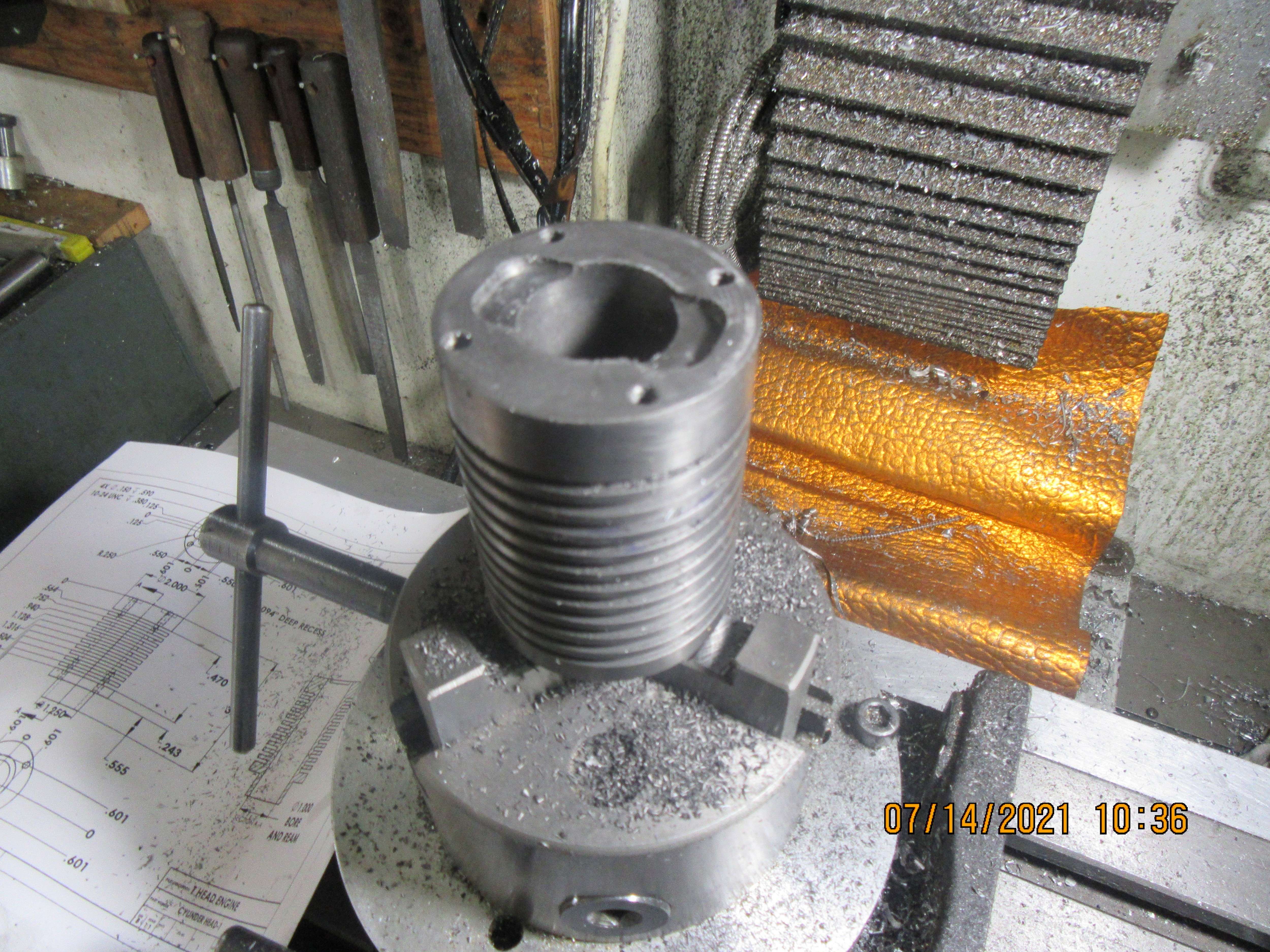
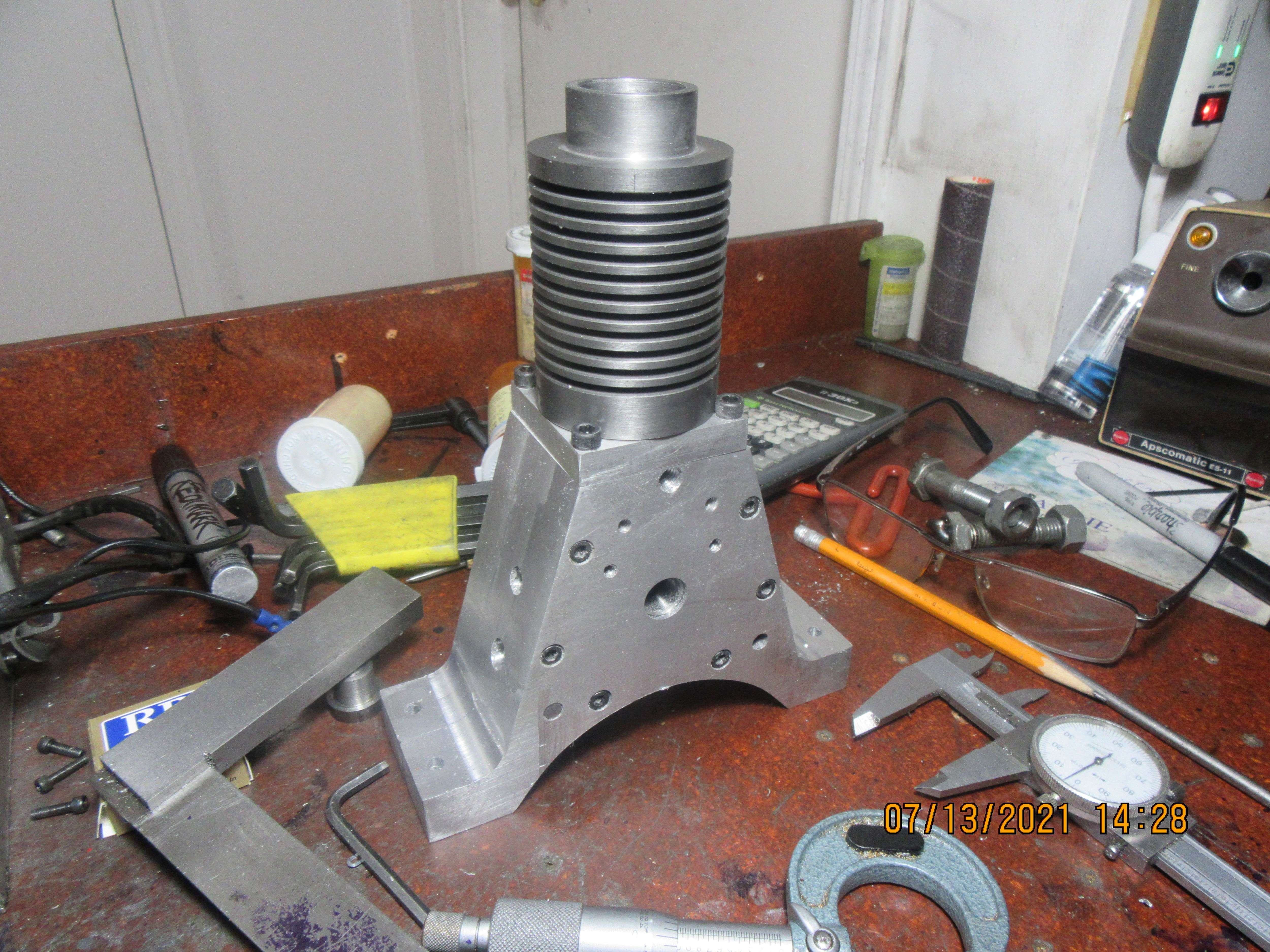
We have a cylinder. It is pretty, it fits where it's supposed to, and after honing the bore with a 3 stone brake hone it measures about 1.001" bore. That's all for today folks. I will get some mounting holes drilled in the cylinder tomorrow.---Brian
TCnKb9.jpg
 
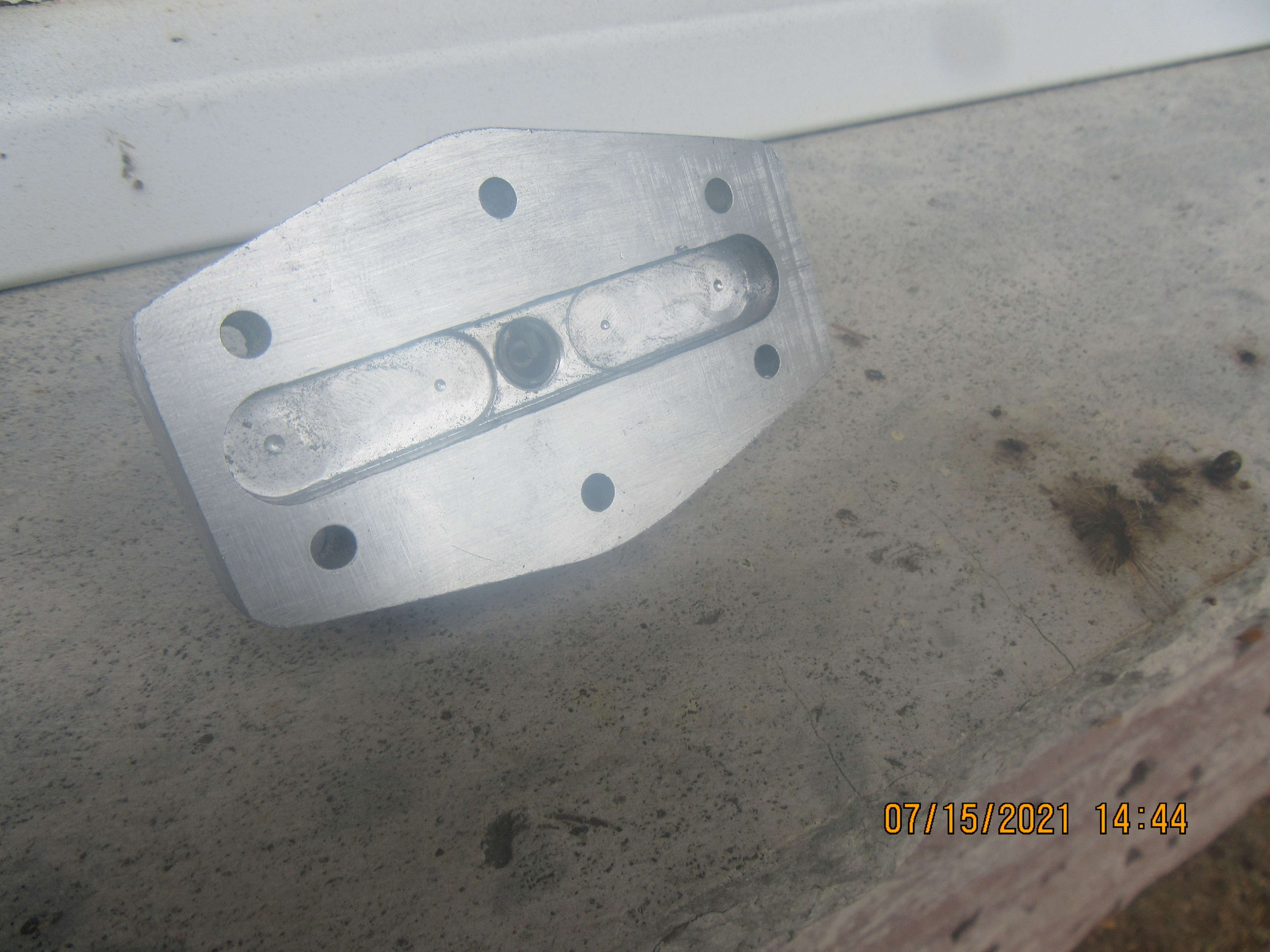
Due to the way this engine is constructed, the swing of the con rod would hit the side of the cylinder bore on it's way to bottom dead center. This cavity in the bottom of the piston aligns with the cavity in the bottom plate which bolts to it, to give clearance for the swing of the connecting rod.
OLIUjZ.jpg
 
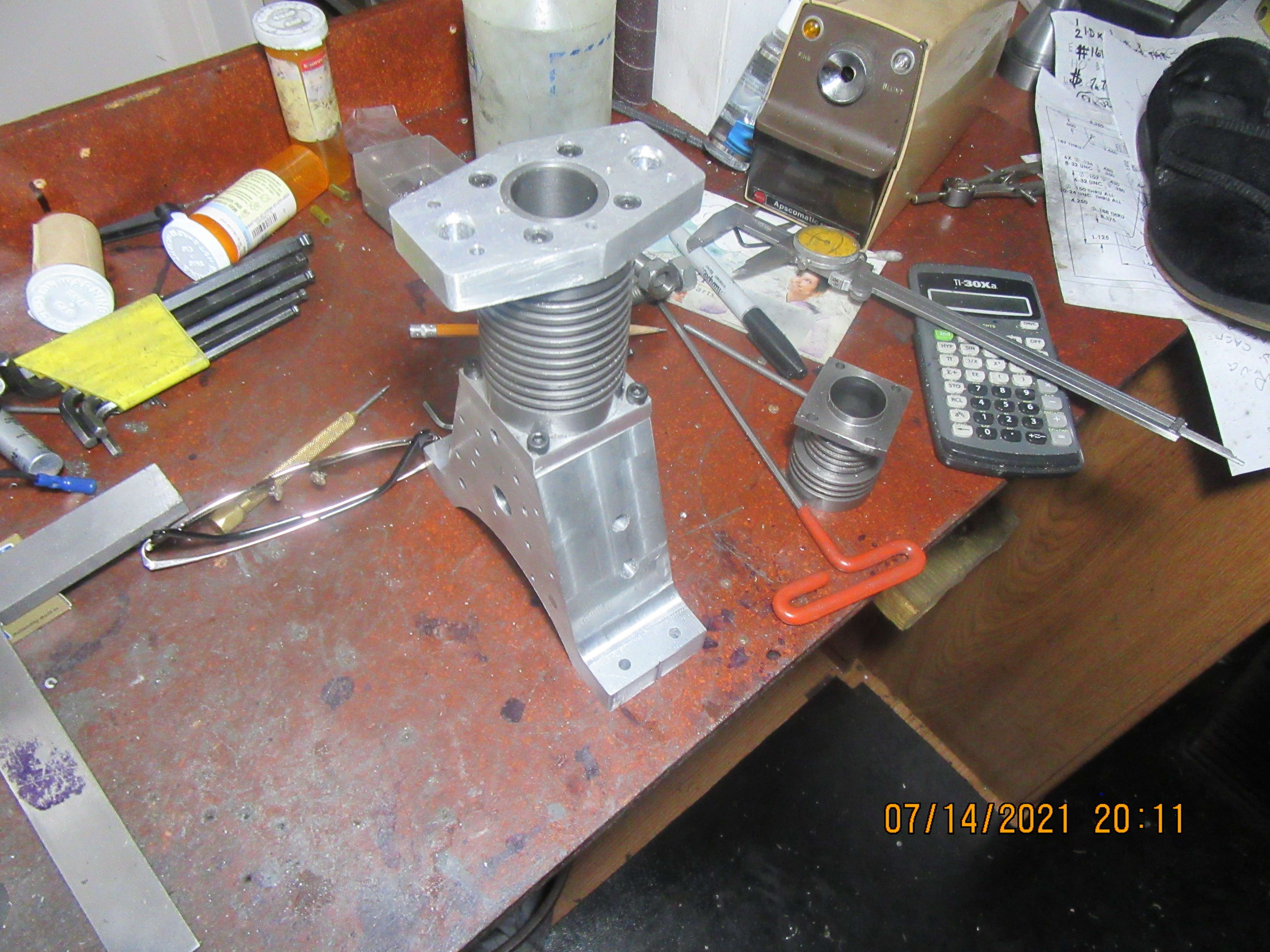
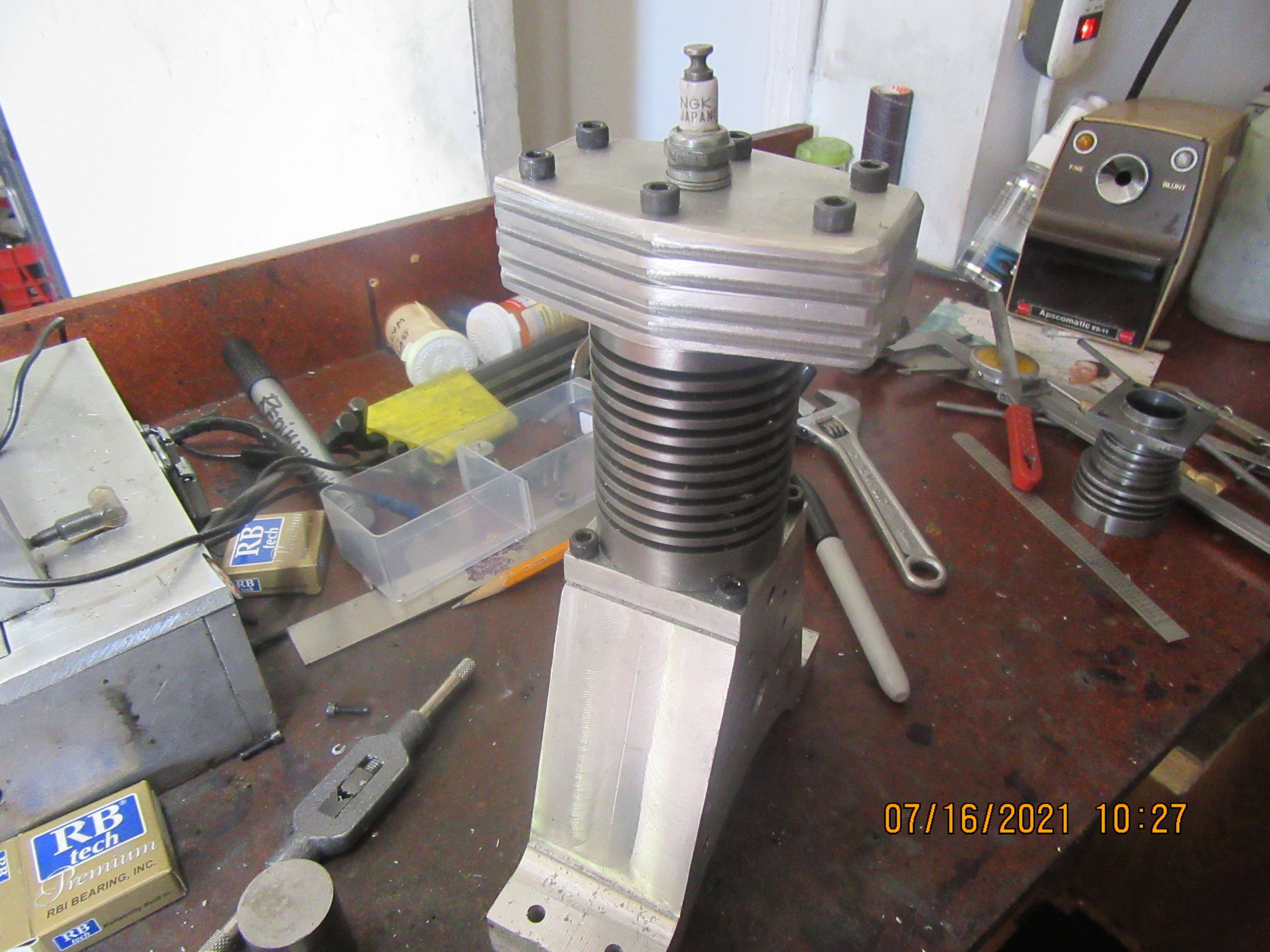
And---The miserable piggy of the day award goes out to this cylinder head. It is finished except for the cutting of the cooling fins, but I've managed to put in an entire day on this part. Some days you eat the bear----Some days the bear eats you!!! The bear eat me today on this part, but I'm pleased with it.
A5LJ3M.jpg
 
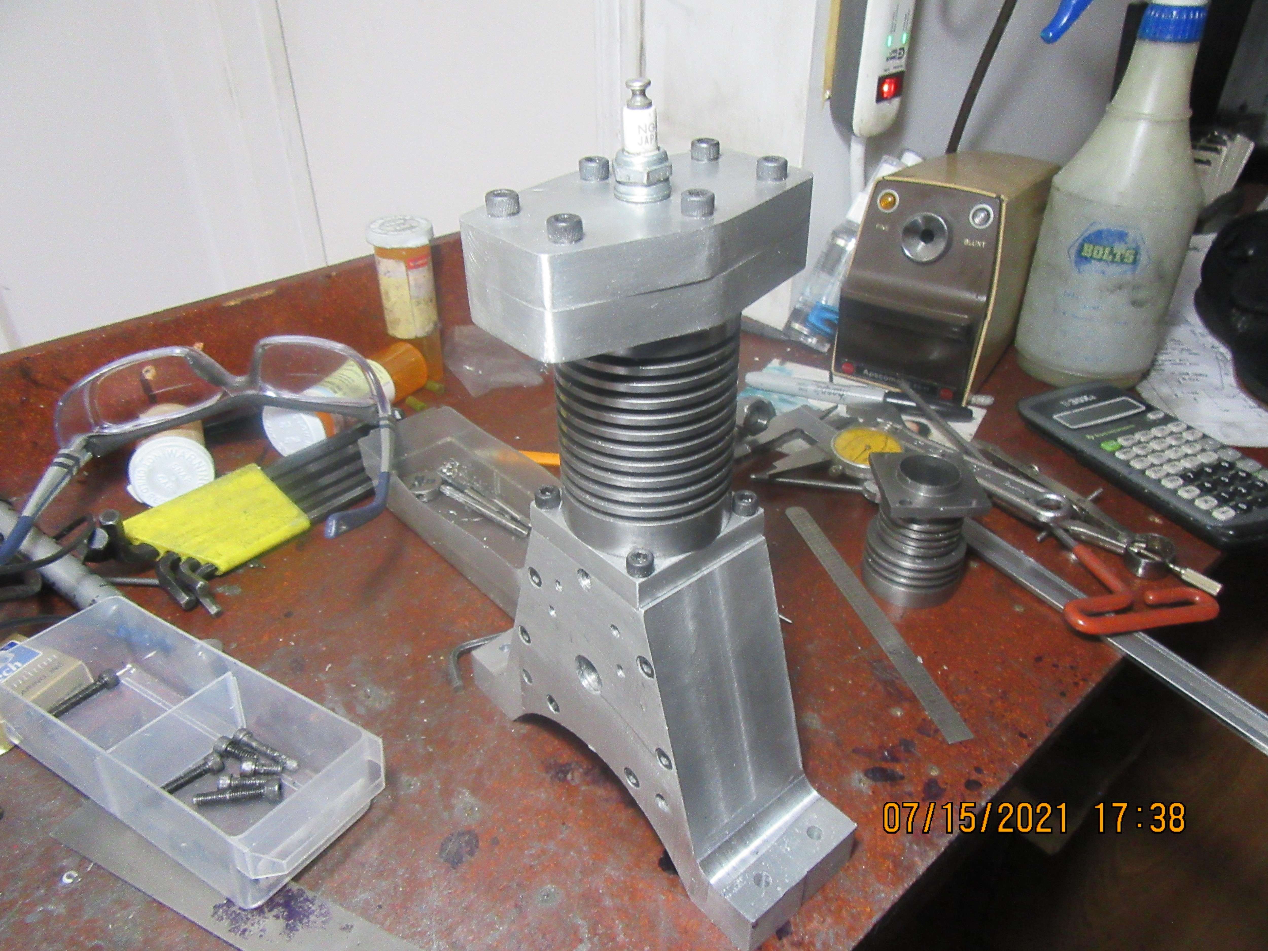
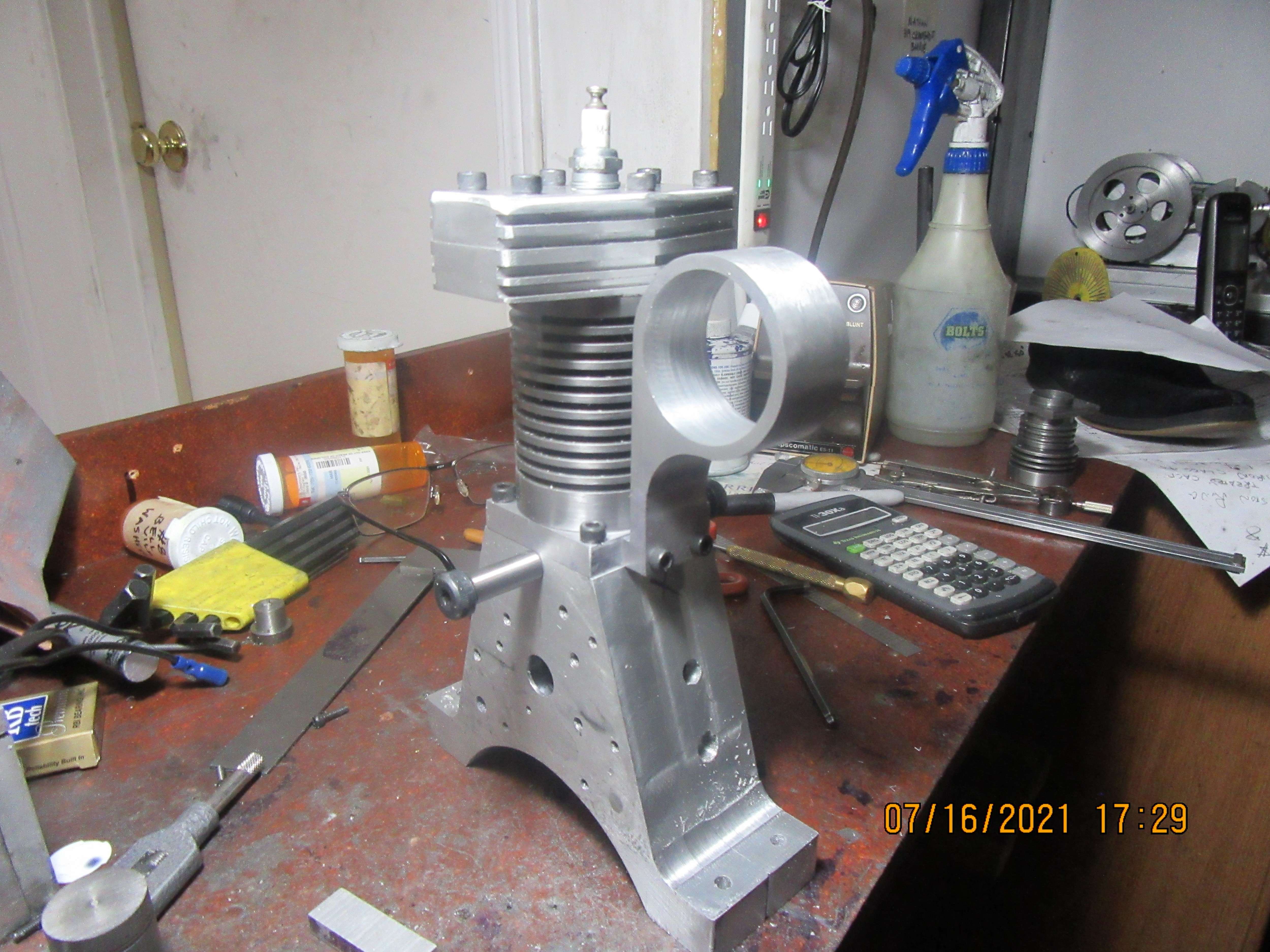
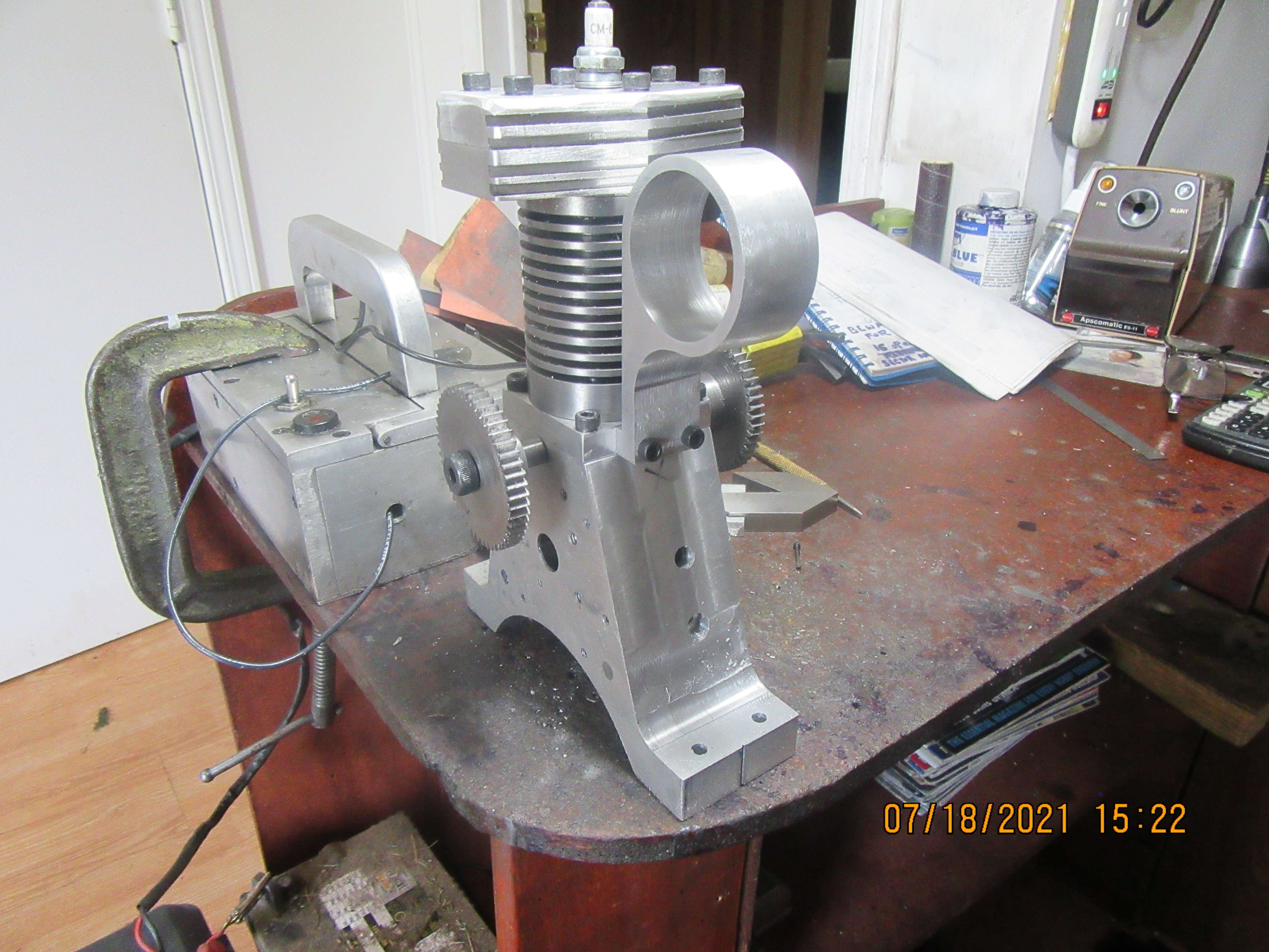
Today I built the cylinder head for my engine. I still have to put the slots in the cylinder head and plate right below it to make cooling fins. The only aluminum part left to build now is the gas tank mount. So, I basically have a whole engine here in six parts. Tomorrow I hope to cut the cooling fins and make the gas tank mount, then it will be on to mechanical things.
Om7cWG.jpg

dWPP54.jpg
 
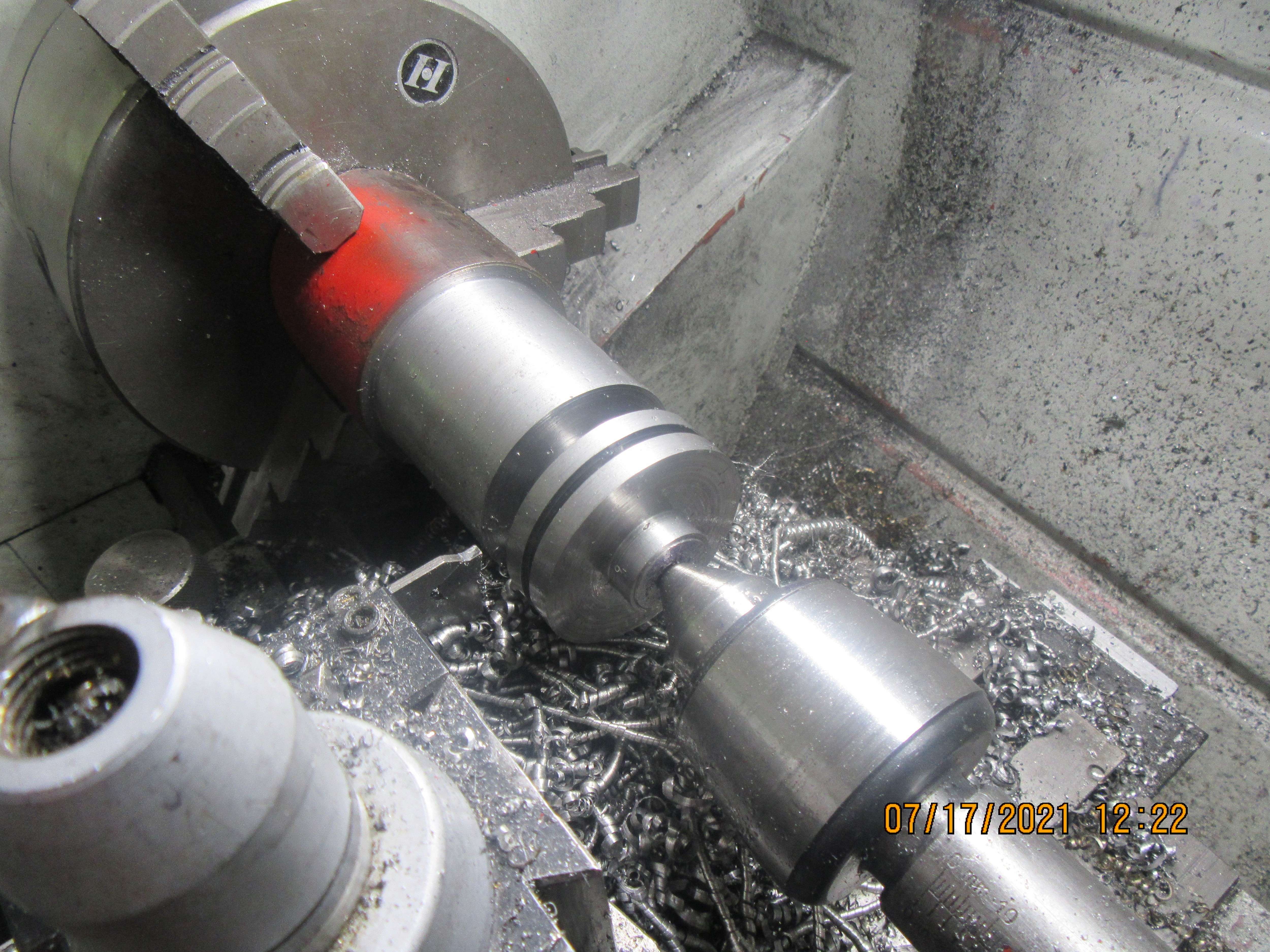
Yes, it is a cylinder, but no, it has nothing to do with this current engine. It is a cylinder from a different engine. I am neck deep in small i.c. engine parts here.
 
We are safe and well here. The tornado was on the far side of town. Had some very heavy rain here but that's all.
We now have "fins" in the cylinder heads. They were cut in using a 0.094" slitting saw. I have to go now and introduce myself to Mr. Lawnmower and Mrs. Whippersnipper. My yard is starting to get a bit jungly with all the rain we've been having.
rniUdF.jpg
 
Today I went to see my nut and bolt guys, and replenished some shcs that I was getting low on. Also bought the two shoulder bolts that will support the cam gears. Found time to make a gas tank mount. Now all of the aluminum parts of the engine main body are finished. Tomorrow I may dive into the mechanical parts.---Brian
Iam4f1.jpg
 
It was on the other side of town from where I lived.---Wife and I were over there driving about 5 minutes before the tornado touched down. Unbelievable rainfall, but we were out of there just minutes before the wind damage.
 
Today seen the beginning of a new engine.---The design phase, at least. After recently seeing an Upshur T head coming together on HMEM and a post by Vederstein about building a T head engine I thought that would be an interesting engine to design and build. I'm in no rush to start building, but I know how that generally works. I spent most of today bringing the design along to this stage, and will probably finish up the cylinder head tomorrow.
Brian,

I'm sure you'll have no problem with this engine. My issue was getting the valves to seal any you've done so many gas engines that portion should be cake for you...

Ved.
 
Here I am, waling away on a piece of 2 1/2" diameter hot rolled to make the 50 tooth gears from. The o.d. of those gears is 2.166" x 1/4" thick plus 7/8" diameter hub on one side.
j0TycV.jpg
 
Got up nice and early this morning and cut both 50 tooth gears. Everything worked out nice, no extra teeth. Maybe I'll do the 25 teeth gears tomorrow. It has been a lovely day here, had a family birthday party for my daughter and I out in my backyard. There are twelve of us now in the family. I'm the oldest at 75, Davy's the youngest at 1 1/2 years.
htMn2t.jpg
 
Brian:
A couple of kind of an unrelated questions:

-What do you use to index gears when you cut them? I frequently use my spin indexer but that works only for 1 degree increments or evenly divided into 360 so I would tend to go for 48 tooth and 24 tooth.

-I assume that the alum box with the switch and handle is an ignition box. I assume that it contains an automotive coil and condenser hooked to a 6 volt or 12 volt battery to work with automotive points.
 
Got up nice and early this morning and cut both 50 tooth gears. Everything worked out nice, no extra teeth. Maybe I'll do the 25 teeth gears tomorrow. It has been a lovely day here, had a family birthday party for my daughter and I out in my backyard. There are twelve of us now in the family. I'm the oldest at 75, Davy's the youngest at 1 1/2 years.
htMn2t.jpg
Brian, when you get time I would be interested in knowing what equipment is required to cut gears. Bevel gears obviously must use a different technique and cutter? You seem to make it sound so simple but I am thinking it is only be because you know what you are doing, but it is still a machining mystery to me.
John
 
I cut my gears using a rotary table with indexing plates and a set of 8 different gear cutters, which are mounted to the spindle of my vertical mill. Each gear cutter covers a range of pitch diameters, so it is not a "one size fits all" kind of thing. There are charts available for a rotary table telling which index plate to use and how many turns and part turns of the handle on the rotary table to move it thru the correct number of degrees of arc to yield the correct number of "teeth" for a specified pitch diameter. It sounds far more complex than it really is.
 

Latest posts

Back
Top