You are using an out of date browser. It may not display this or other websites correctly.
You should upgrade or use an alternative browser.
You should upgrade or use an alternative browser.
Stirling Fan
- Thread starter doc1955
- Start date

Help Support Home Model Engine Machinist Forum:
This site may earn a commission from merchant affiliate
links, including eBay, Amazon, and others.
doc1955
Gone
- Joined
- Aug 26, 2009
- Messages
- 1,261
- Reaction score
- 168
Thanks ! Dean
Thanks ! KustomKB
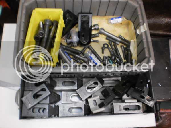
The clamps I am using I got from a 5s sale they had where I work. Every month they sell off thing they don't use or excess things.
I thing I payed $10 for a box of miscellaneous stuff and they were in the box.
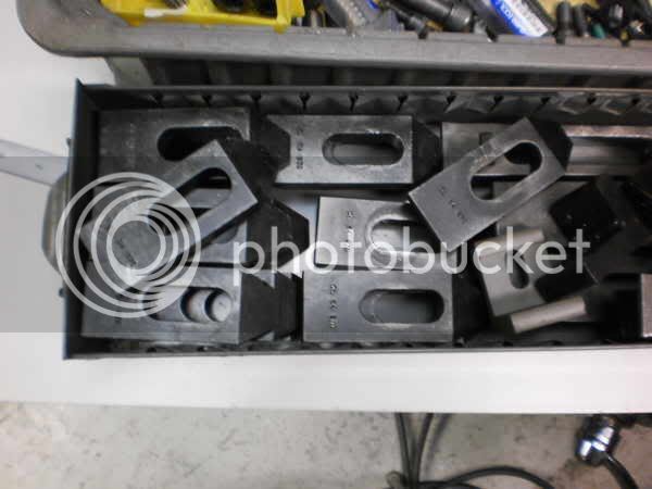
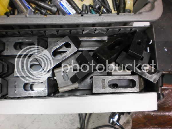
I have a bunch of of toe clamps to way more than I'll ever use was going to take some pics and offer them here for shipping cost just haven't got around to it.
doc1955
Gone
- Joined
- Aug 26, 2009
- Messages
- 1,261
- Reaction score
- 168
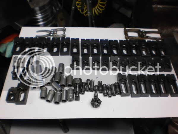
Here is what was in a box I purchased at a sale no one else bid on it I got it for $10.00
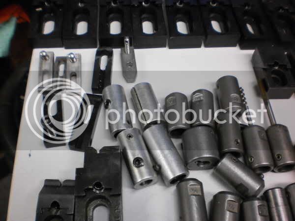
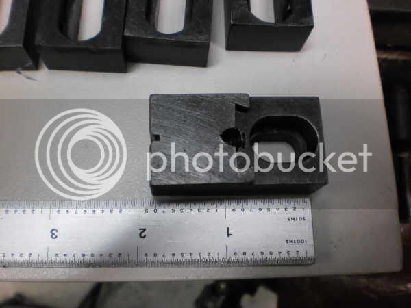
Here is a link to the carrlane page
http://www.carrlane.com/Catalog/index.cfm/index.cfm?FuseAction=PartCheck&Product_ID=539&pn=CL-1-SAC
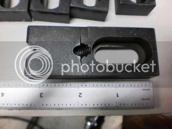
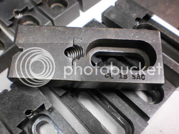
Here is the link to the carrlane page for this clamp.
http://www.carrlane.com/Catalog/index.cfm/index.cfm?FuseAction=PartCheck&Product_ID=539&pn=CL-15-SAC
If anyone could use any and are willing to pay shipping cost they are welcome to let me know.
There are way more that I'll ever use. Usually you only need 3 to clamp plates or parts down.
doc1955
Gone
- Joined
- Aug 26, 2009
- Messages
- 1,261
- Reaction score
- 168
Well it's been a week since I turned a spindle it been hot and humid here plus all kinds of storms.
They are saying the weather is going to start settling down I hope they are right.
I need to get moving the sooner I get done the sooner I'll have a breeze :big: :big:
I may have to break down and get air installed.
They are saying the weather is going to start settling down I hope they are right.
I need to get moving the sooner I get done the sooner I'll have a breeze :big: :big:
I may have to break down and get air installed.

$154.75 ($1.38 / oz)
Replacement Combustion Chamber Kit, Burnham V8 and V8H, 1-6 Sec, 108136-01, 1129
Plumbing Planet

$94.99
$109.99
AHS Woodmaster 4400 Maintenance Kit for Outdoor Wood Boiler Treatment
Alternative Heating & Supplies

$426.53
DM14 Engine Build Kit, Metal Engine Build Model Great Metal Material for Engineer for Factory
Easoger Official

$40.02
$49.99
Becker CAD 12 3D - professional CAD software for 2D + 3D design and modelling - for 3 PCs - 100% compatible with AutoCAD
momox Shop

$188.98
TM NEXDYNAMI RE41157 Water Pump Compatible With/Replacement For/John Deere 6200 7400 6300 6600 6500 6400 7220 7600 7200 RE41157
VIVID MARKET CORPORATION

$99.99
AHS Outdoor Wood Boiler Yearly Maintenance Kit with Water Treatment - ProTech 300 & Test Kit
Alternative Heating & Supplies

$29.95
Competition Engine Building: Advanced Engine Design and Assembly Techniques (Pro Series)
Amazon.com Services LLC

$39.99
$49.99
Sunnytech Low Temperature Stirling Engine Motor Steam Heat Education Model Toy Kit For mechanical skills (LT001)
stirlingtechonline

$109.99
AmTech300 - Boiler Treatment Professional Strength (Rust Inhibitor For Outdoor Wood Boilers)
Alternative Heating & Supplies

$649.00
$699.00
FoxAlien Masuter Pro CNC Router Machine, Upgraded 3-Axis Engraving All-Metal Milling Machine for Wood Acrylic MDF Nylon Carving Cutting
FoxAlien Official
doc1955
Gone
- Joined
- Aug 26, 2009
- Messages
- 1,261
- Reaction score
- 168
Well I did a little in the shop today. Every time I get some time for the shop it has to be hot and humid!
Anyway I started on the connecting rods.
Grabbed some stock and milled down the thickness to size.

Scribed out position of holes.
After drill and reaming holes I took a 1/4 stripper bolt(shoulder screw)and mounted iy with a 5c collet to cut under cuts and cut end radius on each rod.

I clamped a piece of stock to my material to just have a tad more control as I wanted to climb cut around the boss to get a better finish.

I have found as long as you keep your end mil size small you can climb or conventional cut with out to many problems.

Then I put them back straight in the vise and milled the sides. All this milling was done to scribe lines just though I'd mention that. I scribe a line make my cut and blend to it.

Here they are still attached to the main stock.
And cut off.

Now I need to set them up and mill the taper on the side to taper the small end down the the proper size and mill the slot oh yeah the pockets it the sides also. Couldn't take the heat even with a fan running so it will have to wait until next time. I really do have to convince the miss's that we need to put air in the shop.
Anyway I started on the connecting rods.
Grabbed some stock and milled down the thickness to size.

Scribed out position of holes.
After drill and reaming holes I took a 1/4 stripper bolt(shoulder screw)and mounted iy with a 5c collet to cut under cuts and cut end radius on each rod.

I clamped a piece of stock to my material to just have a tad more control as I wanted to climb cut around the boss to get a better finish.

I have found as long as you keep your end mil size small you can climb or conventional cut with out to many problems.

Then I put them back straight in the vise and milled the sides. All this milling was done to scribe lines just though I'd mention that. I scribe a line make my cut and blend to it.

Here they are still attached to the main stock.
And cut off.

Now I need to set them up and mill the taper on the side to taper the small end down the the proper size and mill the slot oh yeah the pockets it the sides also. Couldn't take the heat even with a fan running so it will have to wait until next time. I really do have to convince the miss's that we need to put air in the shop.
doc1955
Gone
- Joined
- Aug 26, 2009
- Messages
- 1,261
- Reaction score
- 168
Finished the connecting rods and started the displacer head.

Cutting pocket.

Cutting taper used a drill to locate part for taper. Used a .062 in the small end then calculated what size I needed in the larg end to put it at the right angle.

Just need to be debured and a little blending.
Squared up some stock for the heads.

Dialed in on the lathe in the 4 jaw to cut the interface for the cylinder and drill and ream center hole for the bushing for the displacer rod.


Back to the mill.


Thats it for today next time finish the heads and start the bearing standards.

Cutting pocket.

Cutting taper used a drill to locate part for taper. Used a .062 in the small end then calculated what size I needed in the larg end to put it at the right angle.

Just need to be debured and a little blending.
Squared up some stock for the heads.

Dialed in on the lathe in the 4 jaw to cut the interface for the cylinder and drill and ream center hole for the bushing for the displacer rod.


Back to the mill.


Thats it for today next time finish the heads and start the bearing standards.
doc1955
Gone
- Joined
- Aug 26, 2009
- Messages
- 1,261
- Reaction score
- 168
Thanks Kevin!
Thanks Dean!
I played hookie and called in and took a vacation day so I could play in the shop for a while today.
Set up and drilled the bolt pattern for mounting to the displacer. Nice thing was these are symmetrical
so one move on x and y and just rotate part in vise against stop and you can drill ll the holes in one set up.

Holes spot drilled.
 \
\

drilling holes

set up and mill steps in the side for bearing standard mounting surfaces.

drill and tap holes to mount bearing standards

parts completed

material for the bearing standards

Don't know if it was ever mentioned but when you have more than 1 part to do put several layers of paper in the front and all the parts will be held securely.

Holes drilled the bearing hole drilled and reamed to size.

parts pined together and used to set parts at angle in vise with a set block uder small hole side.

Angle milled.

parts with angles milled on both sides.

parts mounted with stripper bolt in 5c collet to mill end radius again clamped lever to parts to help control swing.

Man I like my stripper bolts!

Part completed.

Oh darn the Noid is pointing out we're missing a couple parts.
Seems I only made 2 bearing standard so I get to do them again oh well.
After I get the next 2 bearing standards done I'll give the crank arms a go.
Thanks Dean!
I played hookie and called in and took a vacation day so I could play in the shop for a while today.
Set up and drilled the bolt pattern for mounting to the displacer. Nice thing was these are symmetrical
so one move on x and y and just rotate part in vise against stop and you can drill ll the holes in one set up.

Holes spot drilled.


drilling holes

set up and mill steps in the side for bearing standard mounting surfaces.

drill and tap holes to mount bearing standards

parts completed

material for the bearing standards

Don't know if it was ever mentioned but when you have more than 1 part to do put several layers of paper in the front and all the parts will be held securely.

Holes drilled the bearing hole drilled and reamed to size.

parts pined together and used to set parts at angle in vise with a set block uder small hole side.

Angle milled.

parts with angles milled on both sides.

parts mounted with stripper bolt in 5c collet to mill end radius again clamped lever to parts to help control swing.

Man I like my stripper bolts!

Part completed.

Oh darn the Noid is pointing out we're missing a couple parts.
Seems I only made 2 bearing standard so I get to do them again oh well.
After I get the next 2 bearing standards done I'll give the crank arms a go.
doc1955
Gone
- Joined
- Aug 26, 2009
- Messages
- 1,261
- Reaction score
- 168
Thanks for the comments Dean and Kevin I appreciate it.
Still have not did any practice soldering yet need to try and get that done before I work on the real thing. I'd hate to get the fan blades made up only to mess up the soldering.
Still have not did any practice soldering yet need to try and get that done before I work on the real thing. I'd hate to get the fan blades made up only to mess up the soldering.
- Joined
- Jan 3, 2008
- Messages
- 2,085
- Reaction score
- 17
Doc,
You've been making great progress since I last checked the thread and all the assembly shots look great also. There's a lot of work in these little fans, but they are sure worth it just to sit back and watch them run.
Bill
You've been making great progress since I last checked the thread and all the assembly shots look great also. There's a lot of work in these little fans, but they are sure worth it just to sit back and watch them run.
Bill
doc1955
Gone
- Joined
- Aug 26, 2009
- Messages
- 1,261
- Reaction score
- 168
Thanks Bill
I've looked at and thought about building my own for some time.
Just hope I'm up to the challenge as I know how finicky stirlings can be.
Plus the fan has me a lttle concerned I've done some silver soldering but defiantly not my forte now if it was tig welding something I wouldn't be sweating it.
I just need to get some test pieces made and get after it.
I really like the looks of Deans stirling he just finished it was a super build!
- Joined
- Jan 3, 2008
- Messages
- 2,085
- Reaction score
- 17
Doc,
This may seem like heresy but it worked quite well on my mini-sterling fan using Jerry's plans. Rather than soft or silver soldering them to the hub, I used JB Weld epoxy. IIRC I used the quick setting version, but had plenty of time to clean up the joints and leave a nice little fillet where the base of the blades fit into the slots on the hub. After a couple of years now and lots of run time, they haven't let go yet.
Bill
Similar threads
- Replies
- 27
- Views
- 5K
- Replies
- 0
- Views
- 315




![MeshMagic 3D Free 3D Modeling Software [Download]](https://m.media-amazon.com/images/I/B1U+p8ewjGS._SL500_.png)


