It's amazing what one old guy can do when he has some plywood, some metal rollers, and a cherry-picker engine hoist. The lathe came out of my shop, thru my office, into the main garage and onto my truck. It is now in Concord where the Busy-Bee main Ontario center is. I just got home and eat supper.
You are using an out of date browser. It may not display this or other websites correctly.
You should upgrade or use an alternative browser.
You should upgrade or use an alternative browser.
Stephenson's Rocket--Working Model
- Thread starter Brian Rupnow
- Start date

Help Support Home Model Engine Machinist Forum:
This site may earn a commission from merchant affiliate
links, including eBay, Amazon, and others.
olympic
Well-Known Member
Oops! Just read that your lathe is in for repair. Let us know what went wrong.
Anyway::
Many motors have a reset button to protect against overheating and power surges. Look for that and press it.
My Busy Bee lathe's magnetic switch once gave out. A multimeter helped pinpoint the problem, and Busy Bee quickly mailed me a new switch. That beats hauling the lathe off to the Big Smoke....
- Joined
- Dec 31, 2010
- Messages
- 818
- Reaction score
- 218
Check the thermal overload on the motor contactor / starter / relay. Mine quits occasionally in automatic feed with long medium depth cuts (heavy motor load). It's just a push button to reset it right on the contactor. I think the thermals get weak over time. They can be replaced. Hopefully they don't take you for a ride at the repair place.
I don't do electrics. If a machine quits, I can #1-Check that the circuit breaker hasn't tripped and that I still have 110v at the outlet. #2 check the glass fuse on the front of the lathe and make sure it is okay, and #3--Press the thermal cutout switch on the motor in case the motor has overheated and tripped it. Anything beyond that is purely guess work for me. I can do almost anything mechanical, but I know my limitations when it comes to electrical stuff. The trip to Concord in the north end of Toronto took an hour. The big deal was getting the lathe from my machine shop out to my main garage, and that went very well. I like to play Superman once in a while.
Aarghhh Billy--I think there's a wheel in sight!!! Got my lathe troubles sorted and just finished the first outer rim. Lookin' good so far. Mighty scary stuff parting off at that diameter.
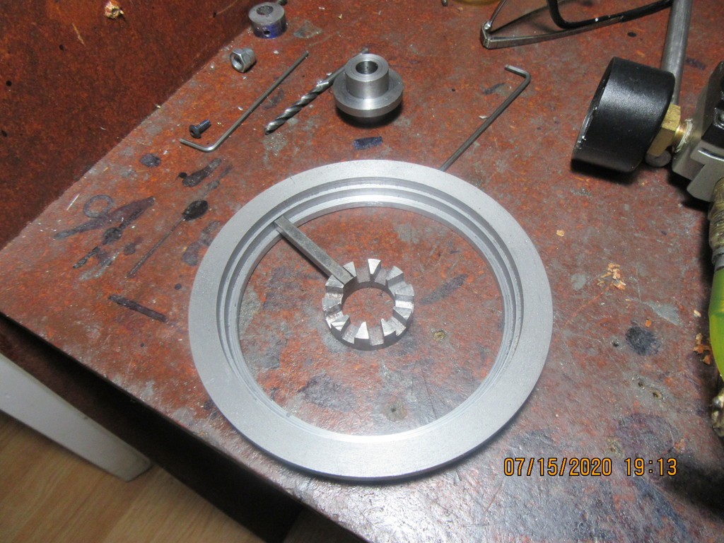

Richard Hed
Well-Known Member
- Joined
- Nov 23, 2018
- Messages
- 2,743
- Reaction score
- 727
So tell us what was the prob? what was the solution?Aarghhh Billy--I think there's a wheel in sight!!! Got my lathe troubles sorted and just finished the first outer rim. Lookin' good so far. Mighty scary stuff parting off at that diameter.


$99.99
AHS Outdoor Wood Boiler Yearly Maintenance Kit with Water Treatment - ProTech 300 & Test Kit
Alternative Heating & Supplies

$89.99
Outdoor Wood Boiler Water Treatment Rust Inhibitor- AmTech 300 & Test Kit
Alternative Heating & Supplies

$34.74
$49.99
Becker CAD 12 3D - professional CAD software for 2D + 3D design and modelling - for 3 PCs - 100% compatible with AutoCAD
momox Shop

$39.99
$49.99
Sunnytech Low Temperature Stirling Engine Motor Steam Heat Education Model Toy Kit For mechanical skills (LT001)
stirlingtechonline
![DreamPlan Home Design and Landscaping Software Free for Windows [PC Download]](https://m.media-amazon.com/images/I/51kvZH2dVLL._SL500_.jpg)
$0.00
DreamPlan Home Design and Landscaping Software Free for Windows [PC Download]
Amazon.com Services LLC

$599.00
$699.00
FoxAlien Masuter Pro CNC Router Machine, Upgraded 3-Axis Engraving All-Metal Milling Machine for Wood Acrylic MDF Nylon Carving Cutting
FoxAlien Official
Richard---See this. Lathe Moving Dolly
Richard Hed
Well-Known Member
- Joined
- Nov 23, 2018
- Messages
- 2,743
- Reaction score
- 727
What was wrong with your lathe? How did they fix it?Richard---See this. Lathe Moving Dolly
Triple_buzz
New Member
Brian, wish I had known you have the same lathe as me, in UK it is branded as a Warco, I had same problem and luckily found it quickly as it had been working before I took the side panel off. Micro-switch now by-passed. Nice 'Rocket' model, I am slowly designing and building 5" gauge of the 'Royal George'. Hope to have it in steam sometime next year.
Aarghhh Billy--I think there's a wheel in sight!!! Got my lathe troubles sorted and just finished the first outer rim. Lookin' good so far. Mighty scary stuff parting off at that diameter.
Yikes that would be scary. Was this a piece of pipe or did you gnaw the centre out of a solid piece?
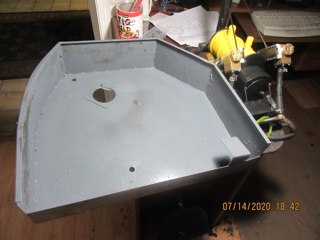
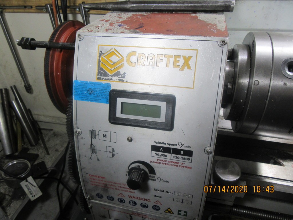
This is what was wrong with my lathe One picture is of the gear cover that sets on the end of my lathe to protect my fingers from the gears. Notice the bent bracket at the lower right corner of it. That bent bracket pushes on a switch which disables the electrics on the lathe if the guard is removed. I haven't had that cover off the lathe in more than a year. Somehow---Perhaps metal fatigue? the bracket bent far enough that it no longer pushed on the button, and consequently the lathe stopped right in the middle of a cut. The switch it presses on is right below the gears and is virtually impossible to see unless you stand on your head to look for it. When I left the lathe in Concord at Busy Bee, I told them that my rpm indicator only worked intermittently and please either fix it or replace it, as well as please fix whatever is wrong that I have no power to the lathe. They replaced the rpm indicator, scratched their heads a bit and then found that bending the bracket by hand fixed things so it pushed the button and restored power to the lathe. I either didn't know, or else forgot that switch was even there.They charged two hours labor and the price of the new readout. My bill came to $129. So, they treated me quite honestly I think. They could have told me it needed a new motor and charged me another couple of hundred dollars but they didn't.


I agree, I think they were very fair with you.
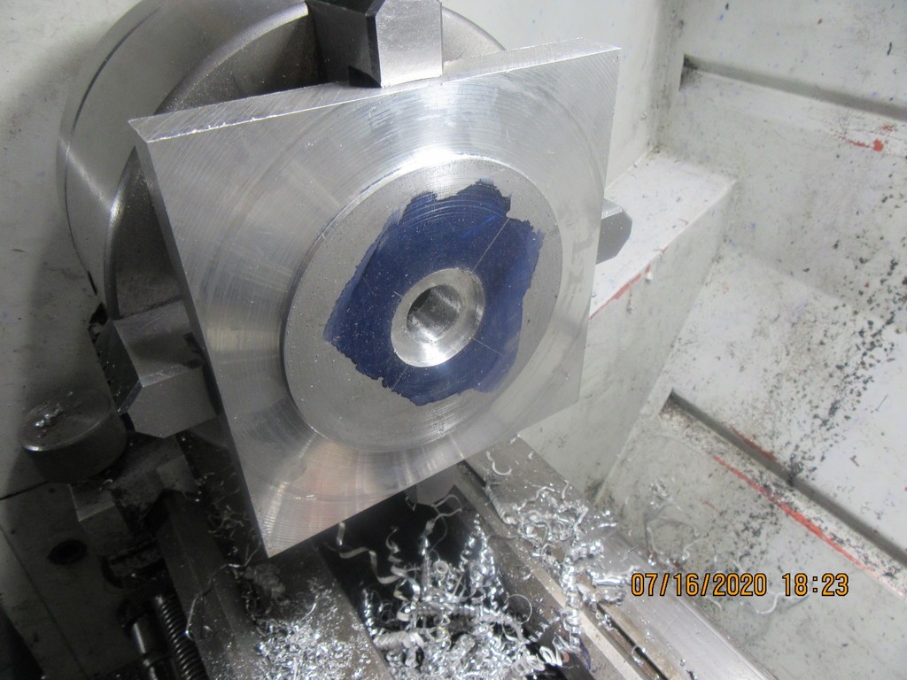
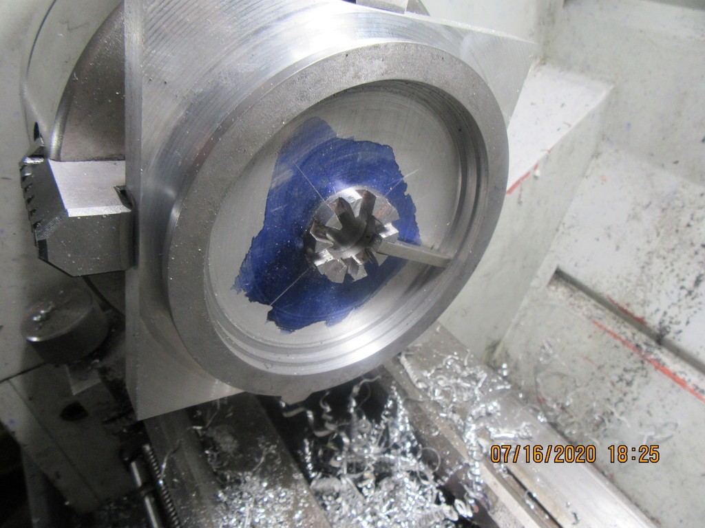
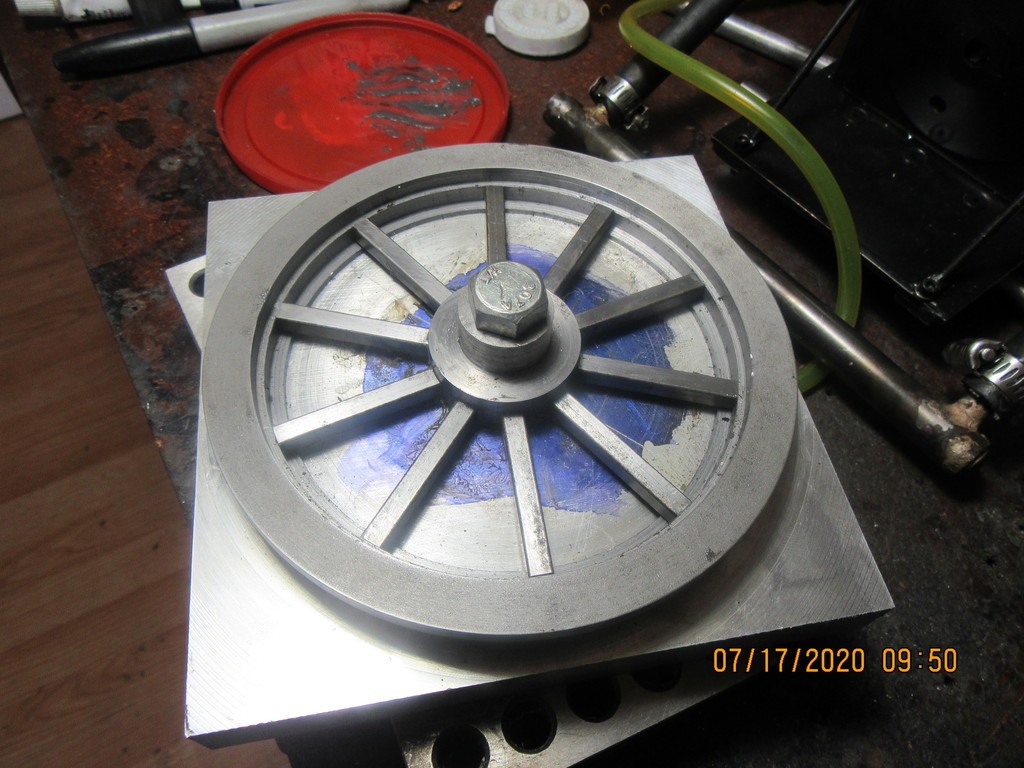
Now it's time to get into some complex stuff. To assemble all of the wheel parts and keep them all correctly positioned in relationship to each other, we have to use a "jig".--Also called a "fixture". In each wheel there will be 13 parts. An inner hub to align the spokes, a centering hub which fits inside the inner hub to adapt it to the axle, 10 spokes, and an outer rim. My plan is to use J.B. Weld to attach the spokes to the inner hub, and to tig weld the spokes to the outer rim. I started out the day by buying a 5" square piece of 3/4" thick aluminum plate which was scribed corner to corner to locate the center, and then a 5/16" center drill was used to put a center "divot" into the plate. The plate was then mounted in my lathe 4 jaw chuck, centered, and a boss was turned that is an exact fit into the inside diameter of the outer wheel rim. Then a 3/4" hole was drilled and reamed thru the center, and a countersunk pocket was put in the center to locate on the outer diameter of the inner hub. The two pictures I have loaded show the fixture after turning operations were completed, and with the inner hub, outer rim, and one spoke set in place. The depth of the turnings was calculated to give .062" of "air" below the spoke, so that it only is supported by the outer rim and the inner hub. There will be more posts as the wheel is developed, but this is my starting point.


Shopgeezer---See post #163
- Joined
- Sep 2, 2011
- Messages
- 1,396
- Reaction score
- 384
i wondered how you would get everything centered up. now I see- with a jig. that's gonna look really cool when you are done I think.
Here we have the first wheel assembled in the jig.--all the spokes were covered with J.B. weld at the inner ends, then slid into the slots in the inner hub. They were all tapped down into the correct position in the outer rim, and then the outside of the centering hub was coated with J.B. Weld and then it was inserted thru the center. A very healthy 3/8" bolt and nut squeezes everything together, and will be allowed to set up for 24 hours. I will then tig weld the outer ends of the spokes to the outer rim. The welds will be on the side of the wheel which faces in towards the center of the Rocket, so will not be visible when all is assembled

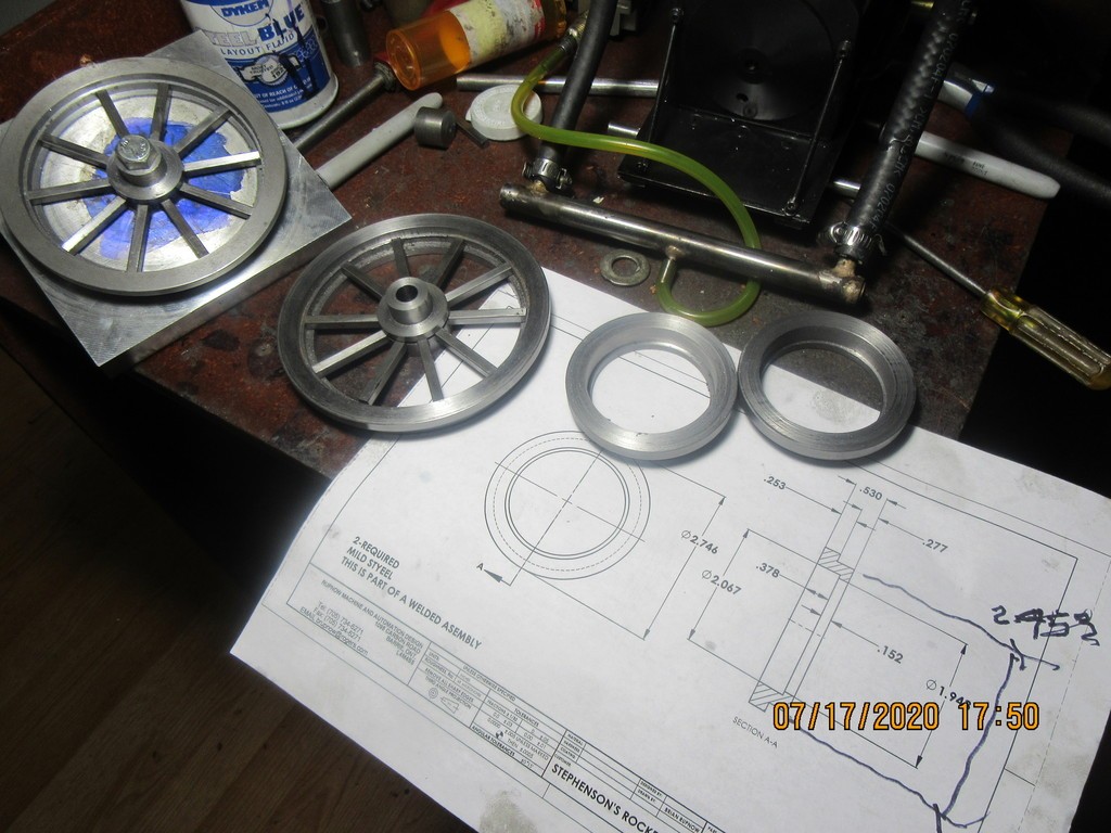
So, what do you do while you wait 24 hours for the J.B.Weld to set up on the wheel in the jig?--Well of course, you make the outer rims for the non driven wheels. Unlike their bigger brothers which were machined from a piece of very heavy wall tubing, these smaller wheels were made from a solid piece of 3" diameter steel. My largest metal drill is 1" diameter. The holes in these smaller rims are 1.943" diameter. Thats a lot of boring passes at 0.015" depth of cut. Tomorrow morning I will make the hubs for the smaller wheels.

Nice wheels, Brian, sure beats cutting them out of solid on the mill. (Don't ask me how I know!). Cheers, Peter.
RonW
Well-Known Member
i wondered how you would get everything centered up. now I see- with a jig. that's gonna look really cool when you are done I think.
Hi Brian, use a hole saw and save the slug for your next roundtoit?RonWSo, what do you do while you wait 24 hours for the J.B.Weld to set up on the wheel in the jig?--Well of course, you make the outer rims for the non driven wheels. Unlike their bigger brothers which were machined from a piece of very heavy wall tubing, these smaller wheels were made from a solid piece of 3" diameter steel. My largest metal drill is 1" diameter. The holes in these smaller rims are 1.943" diameter. Thats a lot of boring passes at 0.015" depth of cut. Tomorrow morning I will make the hubs for the smaller wheels.

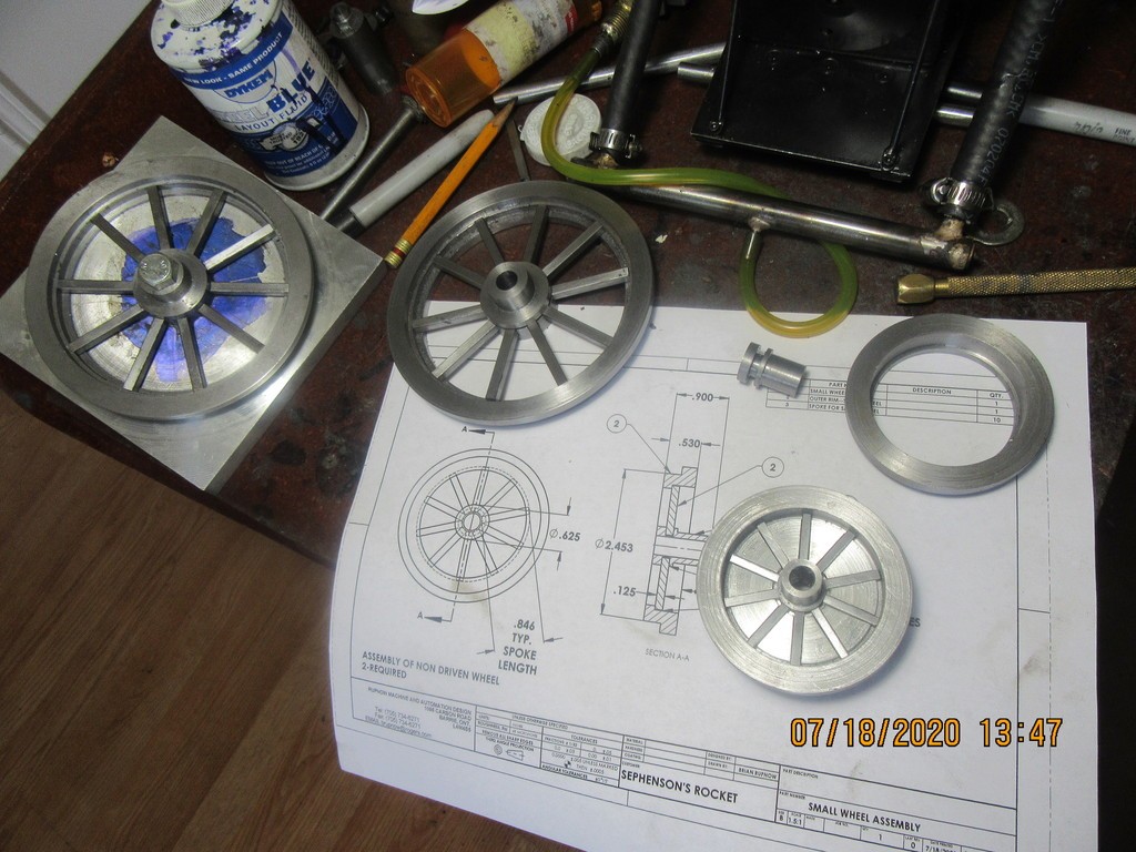
This morning I completed the hubs for the two smaller non-driven wheels, and machined a fixture to hold everything in position for tig welding. I used up every inch of 1/8" square keystock I had to make spokes for the small wheel that is in the jig. If all goes well with the tig welding, I think these are going to be very nice wheels for the Rocket.

Similar threads
- Replies
- 61
- Views
- 13K
- Replies
- 61
- Views
- 17K
- Replies
- 44
- Views
- 11K
- Replies
- 40
- Views
- 7K
- Replies
- 213
- Views
- 42K


![MeshMagic 3D Free 3D Modeling Software [Download]](https://m.media-amazon.com/images/I/B1U+p8ewjGS._SL500_.png)


