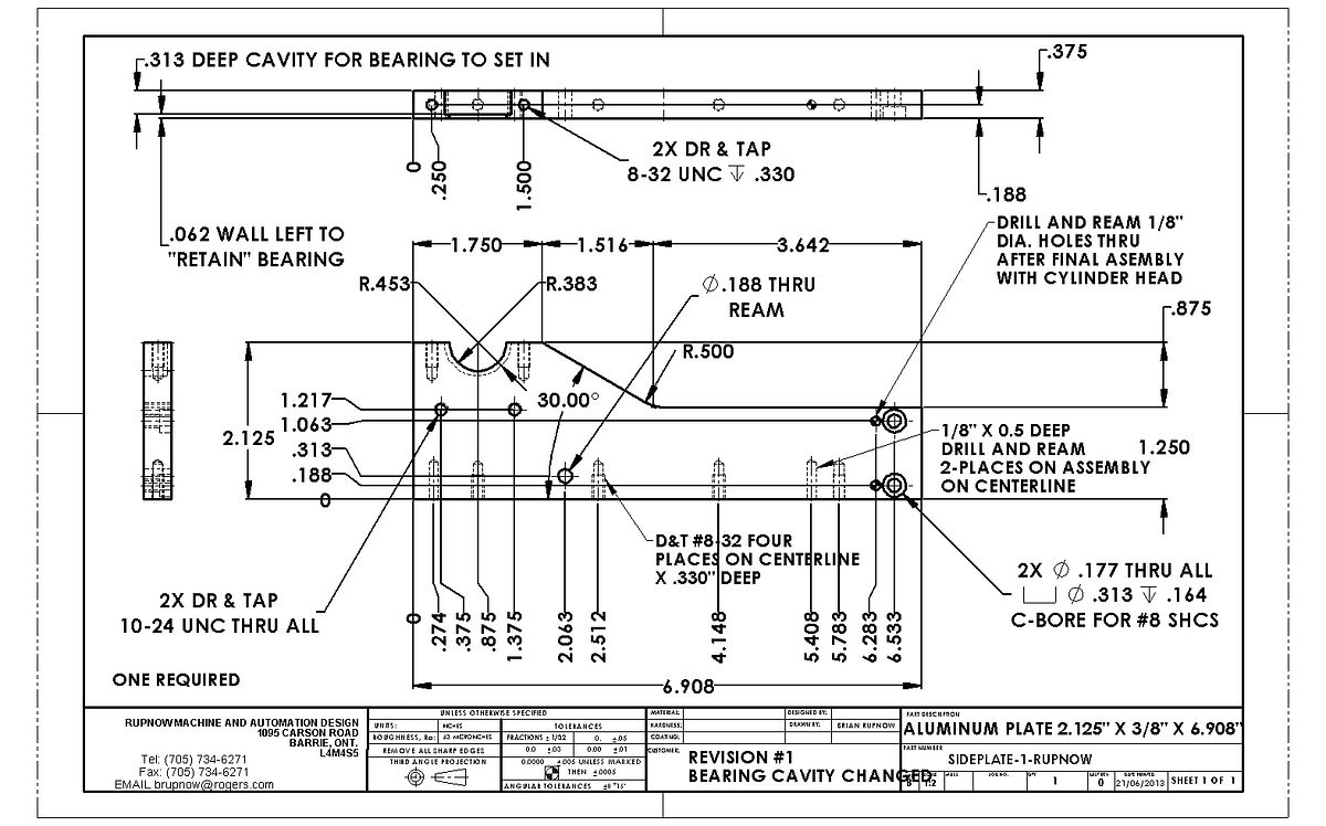
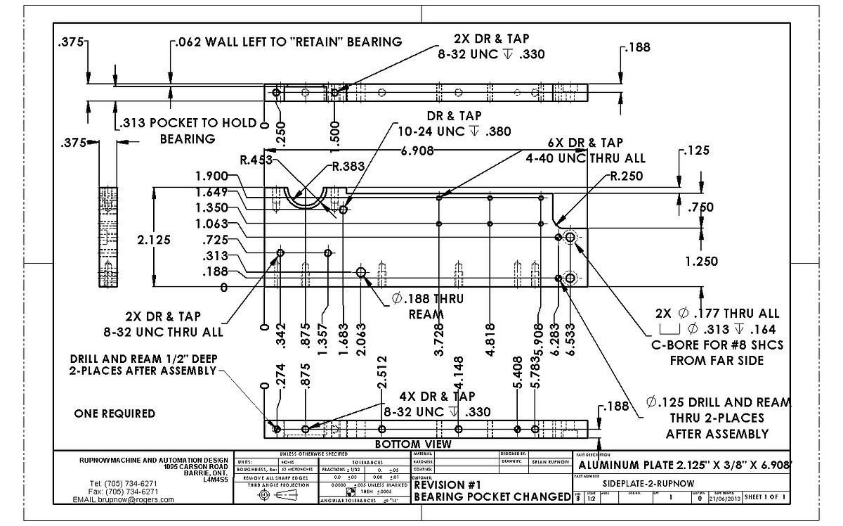
Rupnow i.c. Engine with governor

Home Model Engine Machinist Forum

Help Support Home Model Engine Machinist Forum:

This site may earn a commission from merchant affiliate links, including eBay, Amazon, and others.

Brian Rupnow

Design Engineer
Project of the Month Winner
Joined
May 23, 2008
Messages
15,249
Reaction score
8,525
Location
Barrie, Ontario, Canada
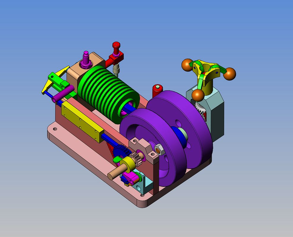
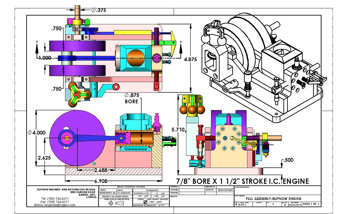
I started thinking about building this engine a couple of months ago and posted it at http://www.homemodelenginemachinist.com/f16/i-may-design-i-c-engine-21117/ I've decided its time to move my thread over to the "A Work in Progress" section of the forum. As usual, when I start thinking I "may" do something, its never very long until I find that I "am" doing it. This build excites me, as I am rather entranced by flyball governors and by hit and miss engines, so what could be better than combining both in one package. I am taking a somewhat "modular" approach to this engine, so it can be built with or without the flyball governor, and as a water cooled version or as an air cooled version. (I am going to supply drawings for both versions). The approach to the crankshaft is somewhat novel, and is based on a 6 cycle engine originally designed by Philip Duclos. This will be an "All ball bearing" engine except for a bushing in the small end of the connecting rod and one in the flyball governor. The 3 ball bearings cost less than a total of $15 Canadian, and the bevel gears driving the flyball governor are $20 each from McMaster Carr. I am hoping to find 10 other people world wide who will build this engine at the same time as I am and post about it. My goal is to make at least one part per week. (There are a total of about 75 parts). All detail drawings will be posted here, and "in process" shots of the parts as I am making them.---Brian
 
Last edited:
Boy this looks sweet Brian!!!! Your talents are priceless.

Greg
 
Brian, do you have a plan of attack as to which parts you intend to machine first? Do you have a BOM yet? What about power supply? When are you going to post solids and drawings? When do you plan to start your one part a week regimen?

I'm digging the design and we can definitely tell your into flyballs lately... Look how big that one is! After all, this engine was designed primarily for the governor!
 
JW what do you mean by power supply, its an IC engine and supplies its own power? Brian has drawn the points so just connect your favorite coil and away you go.

Brian do you feel teh flyballs will have the force to overcome the friction in that rather tortuous linkage? I guess there is only one way to find out;)

J
 
It will have to have a battery, stator or something...
 
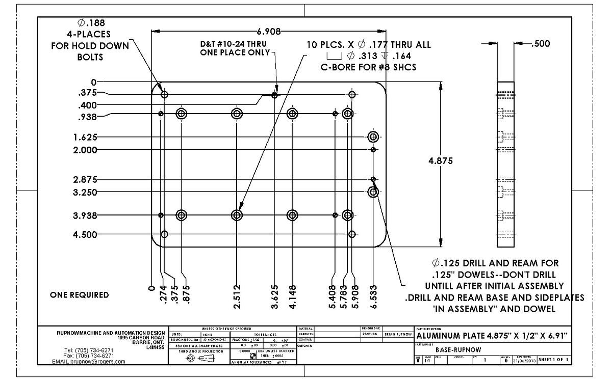
Engine will have a very conventional set of Chrysler ignition points, condenser, 6 or 12 volt coil, and a 6 or 12 volt battery. Fuel will be Naptha gas (Coleman lantern fuel.) The size of the flyballs will be determined using the "suck it and see" basis, although I think the 5/8" balls I have specified should be sufficient based on earlier governors I have built. I will start posting drawings today. I won't be posting models per se' because they have no practical value unless you have 3D cad software to utilize them. What will I machine first?---Well, I have made everything on this engine multiple times, all except for the rather strange crankshaft, so that will probably happen very early in the game. After all, if I can't build the crankshaft, there is no point in making all the other engine parts. First part up will be the baseplate. Second parts will be the sideplates and main bearing caps. Then the crankshaft, in that order. Once we have that much assembly done and have satisfied ourselves that this is a practical method for making a crank (with flywheels which are part of the crankshaft) we will go on with all the rest of the parts.
 
  • Like
Reactions: gus
Flywheel/crank combination should work fine its just like a HD engine and similar to whats used on the Hoglet, just yours are a simpler one piece design though no reason a builder could not shrink a weightier bronze rim onto a steel web
 
Brian, do you the bearing number
I'll pick them up with the material today

And the PDF is not attached


thanks

Luc
 
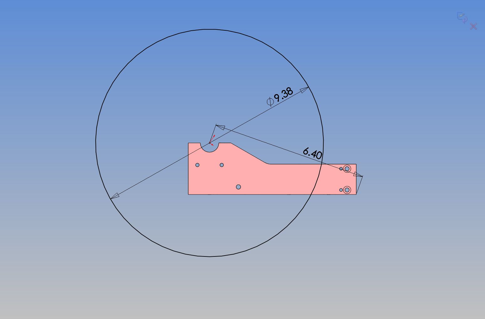
Houston---We may have a problem---Already!!! In the back of my head I have thought all along that I would bore out the bearing cavities in the sideplates and bearing caps by mounting them on the faceplate of my lathe. However--I just did a quick and nasty layout----My lathe has a 9 3/8" faceplate. It will swing 10 diameter" and clear the bed.---You can see my problem. However, all is not lost. I will move the cavity for the bearings flush with the inside of the sideplates and bearing caps and have a 1/16" retainer ridge on the outside of the plates and bearing caps only. That will allow me to bore them on the milling machine. Sure is fun making prototypes!!! New drawings will be posted this evening.
 
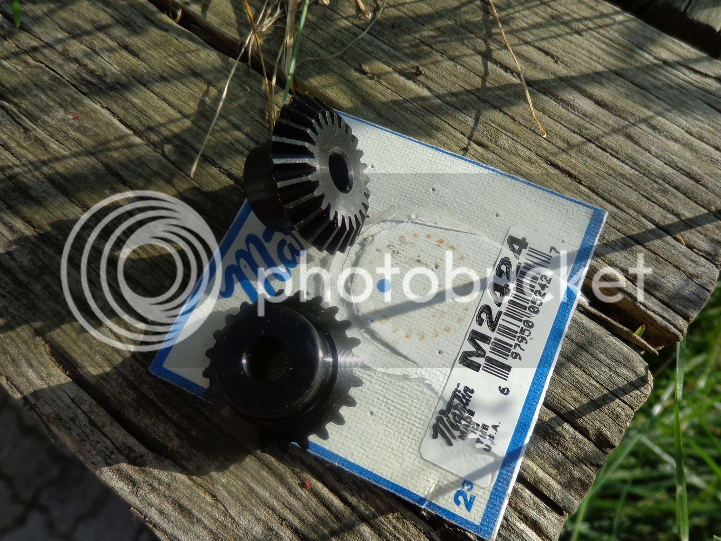
However--Not all the news is negative. My bevel gears just arrived, and they are REALY slick!!! Not bad, considering My friend just ordered them yesterday. They are steel.
 
Hi Brian

Very nice design !
On the "Bearing Cavity" why not just bore it straight thru ? Do you want the side lips for appearance reasons ? I am sure the bearing caps will retain the bearing from moving. If it is an appearance issue how about just doing them on the out side, you probably won't see them on the inside anyway. I think I would fit the bearing caps first and then drill and bore the holes. You could even stack the 2 side plates and drill and ream the smaller hole through both and then just counter bore the second one as a second setup.

And forgive me if this was covered or I am just missing it.......what is actuating the intake valve ? Or does it just get sucked open ?

Scott
 
Last edited:
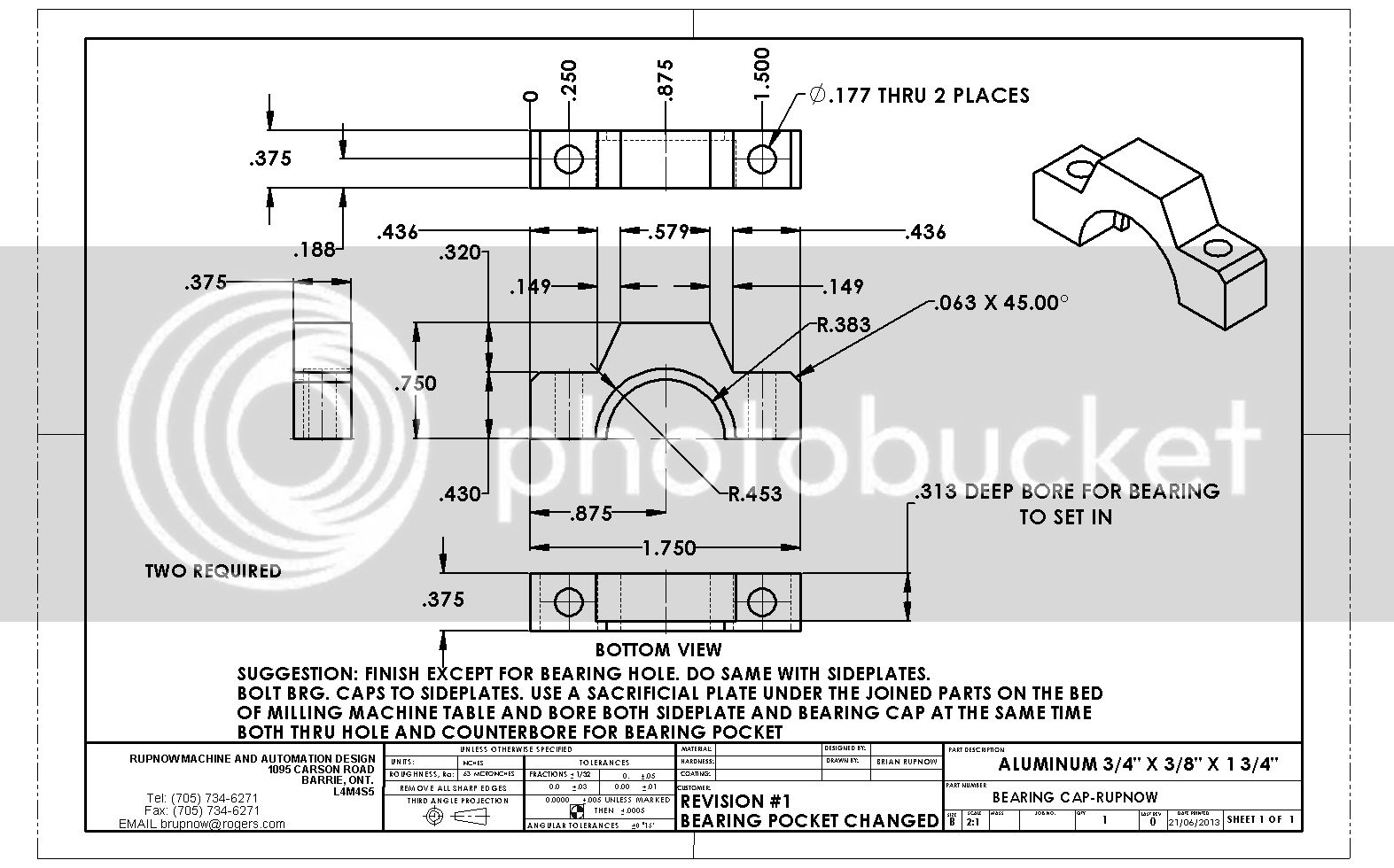
And two bearing caps.--That should keep some of you out of trouble for the weekend at any rate. I have had to revise this drawing and move the bearing pocket over to one side instead of centered as it was previously. I will make the parts I have detailed myself now, before I detail any more.---Brian


View attachment BEARING CAP-RUPNOW.PDF
 
Last edited:
Hi Brian

Very nice design !
On the "Bearing Cavity" why not just bore it straight thru ? Do you want the side lips for appearance reasons ? I am sure the bearing caps will retain the bearing from moving. If it is an appearance issue how about just doing them on the out side, you probably won't see them on the inside anyway. I think I would fit the bearing caps first and then drill and bore the holes. You could even stack the 2 side plates and drill and ream the smaller hole through both and then just counter bore the second one as a second setup.

And forgive me if this was covered or I am just missing it.......what is actuating the intake valve ? Or does it just get sucked open ?

Scott
Yes Scott---It just gets "sucked" open. Its what's known as an "atmospheric intake valve." Works fine on slow revving engines. I wanted to have the bearing restrained from any side to side movement, with only very light pressure from the bearing caps, just enough to keep the outer race from spinning, but not enough pressure to deform the outer race. Seeing as I can't do that operation on my lathe, I have decided to modify the drawings so that the retaining "rim" of material is on one side of the plate only. I chose to have it on the outside of the plates to keep the bearings from drifting outwards, and will put a very thin washer between the flywheels and the inner side of the bearing to restrain it from drifting inwards.---Brian
 
Last edited:
Back
Top