Rockerblock I.C.--Something a little different-

Home Model Engine Machinist Forum

Help Support Home Model Engine Machinist Forum:

This site may earn a commission from merchant affiliate links, including eBay, Amazon, and others.
Random interjection -- I had that exact same phone/fax in my home office for years! I still have at least 2 whole boxes of ink 'rolls' for it under my desk...

And of course I'm still following with interest Brian. I'm sure you'll get it sorted.
 
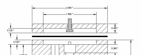
For initial starting with the Jerry Howell demand valve it really requires an activation button making that sits fairly loosely in your 'vent' hole in the top plate. Just make it out a bit of nylon or plastic.

When you press that button, it allows gas through the unit to the carburetor so that combustion can take place.
If you don't have an override button, you will have trouble starting the engine as it will not be able to produce enough vacuum at this lower speed to get the valve working correctly., once started, the valve will work all by itself.

Demand%20valve_zpsoyq0vayl.png


You can see here the button, cross hatched for clarity.

John
 
Finger over the intake and turn it over a few times, same method used to suck fuel up to the carb if you have a low tank position. As the engine can't suck in air it will suck a lot harder on the fuel line and purge the air out bringing the gas with it.
 
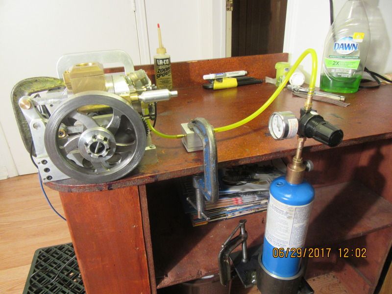
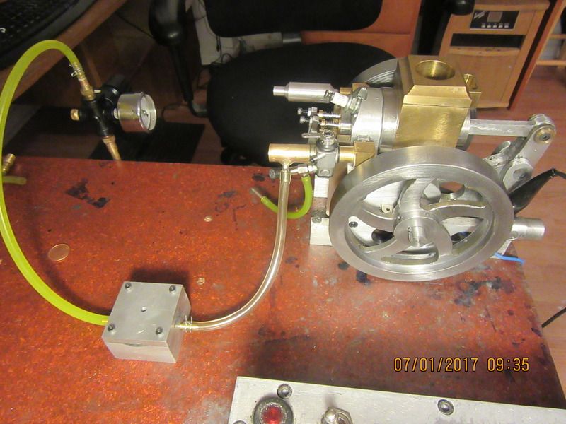
So, here we have it, set up and ready to try. Immediately above the blue propane tank is the shut off valve that was part of the original torch head. Above that is the adjustable regulator which has a gauge in one port, and a plug in the opposite port. Above the regulator is a fitting which I made up from a brass fitting with a 1/8" npt thread and a custom made brass extension silver soldered to it , which fits into my neoprene gas line. The neoprene gas line runs over to the "gas demand valve", and from the gas demand valve up to the fuel inlet on the carburetor. I have tested all of my connections with liquid dish soap, and have hopefully sealed them all, with the help of some Teflon plumbers tape on each threaded fitting. Before I get really crazy and start modifying carburetors, I will try it with the carburetor "as is" and see what happens. I am doing this with my door and window open down in my office to get a bit of cross draft going and disperse any build up of propane in my office.---Brian
 
So--No joy at the moment. I have opened the needle valve two additional turns from where the carb was running happily on liquid fuel, I have checked for spark, and I can see the propane pressure gauge registering anything up to 10 psi. ( I have tried numerous different psi settings, all less than 10 psi). Engine doesn't want to fire at all. I have choked it with my finger completely covering the air intake, but it makes no difference. I pulled the sparkplug and checked for spark, and it has lots of spark. I don't want to modify the purchased carburetor that is currently on the engine. I do have an extra home built carburetor around, and if I can't get my engine to fire at all on propane I may re-jet the carb I have (a matter of enlarging the fuel discharge nozzle) to see if that helps.
 
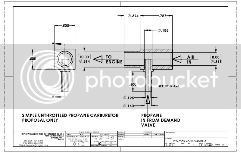
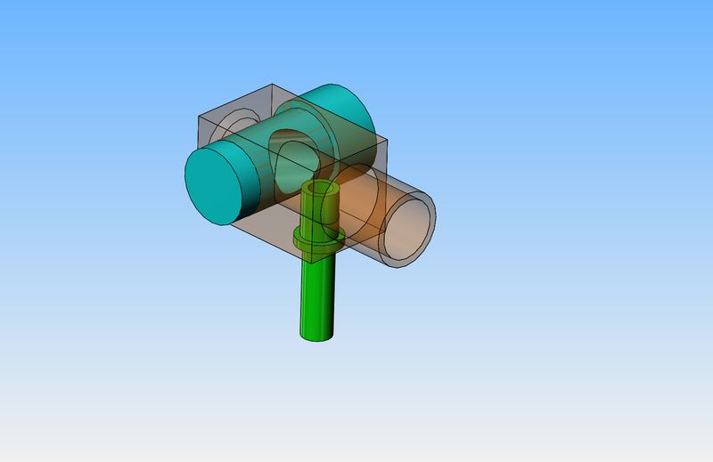
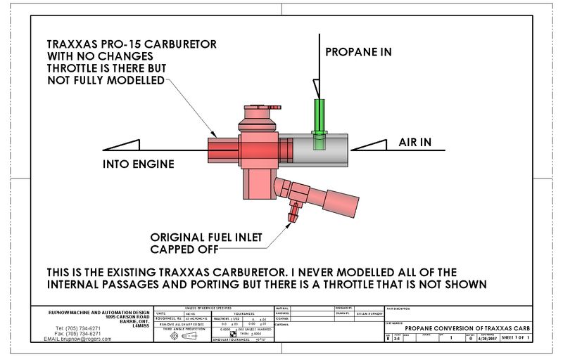
Somebody on another forum who claims to have expertise in using Propane is suggesting a different carburetor. He is suggesting a carburetor with no needle valve to adjust mixture, just a simple pick up tube. The tube itself creates a restriction in the main airflow to create the venturi effect which will signal the gas demand valve for propane flow.The drawing shows a very simple carburetor with no needle valve. I don't show a throttle plate in this drawing, but a throttle plate is simple enough to add. (As per the solid model.) The existing carburetor is held into the brass elbow with some light Loctite. I would remove the existing carb and put this one in it's place.

 
Brian, What a unique looking design. I have looked at some of your other designs and would like to try to build one of them, however I am unable to locate drawings. Could you let me know how to find a list of your engines and a source for drawings.
Thank you,
Bill Lawson
[email protected]
 
Best bet is to type in my name and "youtube" to see some of the many engines I have designed and built. I don't really have a comprehensive list. I have built about 12 "steam" engines and 14 i.c. engines. some of the plans are posted free, some you have to contact me by email and I will sell you a disc with all the drawings.---Brian Rupnow
 
After watching a YouTube video on converting a larger two cylinder engine to run on Propane, I have decided to try this "conversion" instead of an entire new carburetor. This would be very simple to make and add to my existing Traxxas carburetor. There is only an hours work in this, and if it works as well as the engine in the video I would be very pleased.---Brian
 
Converted my standby generator to propane a couple of years ago, the propane
regulator required a vacuum line to the back of the diaphragm to control the flow of propane, the propane was introduced into the top of the carb. above the butterfly.
The regulator had the same button on the rear of the diaphragm, to Prime at start.
I am running a 25 hp twin on 8 psi propane
 
So here we are, ready for round two of the propane game. This set up is as per the video I watched, with a separate venturi tube extending out in front of the carburetor air intake. The small metal pipe which the clear flexible tube is attached to, protrudes approximately half way into the "venturi tube. This will create a restriction in the inrushing air so it will create a low pressure area where the end of the tube is. The carburetor has not been changed in any way. The liquid fuel line which runs up to the bottom of the carburetor has been plugged with a piece of 1/8" steel dowel inserted into the original fuel feed line. The new brass "venturi tube" is a very light press fit over the carburetor air horn with a bit of green Loctite to help it stay in place. The original carburetor throttle should work to control engine speed, same as it always did. I will give the Loctite a few hours to set up, then try the engine again to see what happens.
 
Hello Brian,
Due to computer problems I am unable to send attachments, but I feel you have the basis of a working unit. In principle, similar to a vehicle gas conversion. Will be very interested to see how you fare with this unit. Norm
 
Sadly, I must report that I had no luck at all with Propane. I have tried all of my bag of tricks, and the engine simply won't fire and run on Propane. This is not a really big deal, and like many other things, you don't know until you have tried. I do have a spare gas tank setting around, and by making a simple bracket I can add it to the existing Rockerblock assembly. With the coming of summer, I don't want to spend a lot of time in my machine shop, so I will end this thread now and say a big Thank You to all the people who have followed my build.---Brian
 
Brian, don't think of your demand valve so much as a regulator for pressure of your gas, think in terms of scuba diving. The air from your tank only flows when you draw on it. It's known as a demand regulator also. It will only flow gas when it's asked. Propane forklift is the same way. More people have problems with too rich a mixture of propane than they do with too lean. It takes a surprisingly little amount to make an engine run. If I recall correctly the explosive concentration of propane is somewhere in the neighborhood of 2-10 %. Any more or any less= no joy. With enough patience and persistence I'm certain your motor will run on propane, not throwing in the towel is key. Your ability to create these little gems is amazing. Keep at it and if I can be of assistance don't hesitate to message me, I'm not the sharpest knife in the drawer but I do have a little experience that I will gladly share.
To
 
After my failed attempt to even have the engine fire on Propane fuel, I was beginning to wonder if perhaps the ignition timing or valve timing had "slipped" from the original settings where it ran so well on naptha gas. I had a spare gas tank setting around, so I installed it on the engine, and without readjusting anything the engine fired right up and ran well. I decided to have a 40 minute "endurance run", and about half way thru the run I picked up my camera and shot a short video. That explains the nasty oil on everything.---I had given all of the bearing surfaces a good squirt of lubricating oil and filled the water reservoir before starting the run. The water stays in the reservoir with no problem, but the oil quickly turns black and splashes all over the place.---Brian
[ame]https://www.youtube.com/watch?v=dp0CgAwvBss[/ame]
 
Brian,

Thank you for posting the latest video. I would say the great sound and hit-and-miss kind of makes up for the oil splashes.

Anyway, I know you build your engines to work, not look good on the shelf (which they do, anyway).

--ShopShoe
 
I have a few people around the world building this engine now, and I am being asked about setting the valve timing. The set screws in the cams are difficult to access. I covered how I did this back on post #158, but here is a repeat of the way I did it. I was very lucky and the very first setting I used seems to work fine.
--There is a bit of trickery involved in setting the valve timing. You must have the cylinder head and lifters and rockers all in place, and have the valve lash set at about 0.010" when the lifters are not "up" on the cams. I sawcut a 0.030" slot in the end of the camshaft that is on the same side as the cam gear, so that I could turn the camshaft with a screwdriver. I removed the flywheel on the side where the timing gears are and turned the other flywheel in the direction I intended the engine to run (clockwise when viewed from the side with the gears on.) The set screws in the exhaust cam were tightened at any random spot by reaching up through the bottom of the engine. The intake cam was left loose on the shaft. The setscrews in the cam gear were left loose. The crankshaft gear was tightened on the crankshaft at any random position. I turned the flywheel until the piston was about 40 degrees or so before bottom dead center, then used a screwdriver to turn the camshaft in the opposite direction to the crankshaft until the cam lobe was just beginning to influence the exhaust valve. At that point, I tightened the camshaft gear setscrews. That "locked in" the exhaust valve timing. I then kept turning the flywheel until the piston was about 30 degrees before top dead center. At that point I reached up through the bottom of the engine (with great difficulty) and rotated the intake cam until it was just beginning to influence the intake valve, then I locked it in place. The cam set screws are "accessible" either through the underside of the engine or through the vertical slots in the "bolster" which stiffens the cylinder head plate. If you simply can not get at the screws for the intake side cam, you can remove the other flywheel, the ignition cam, and the entire sideplate to get to the intake cam set-screws to tighten them. I think I covered this in post #158 in the original build thread.---Brian
 
Gee Whiz--I'm going international in a big way. The second Rockerblock engine ever built was just finished by DavidLloyd2 in New Zealand. Cogsy in Australia has a set of the plans, and a fellow in the U.K. also has a set. I just sold a set of plans to a fellow in Spain. I'm pretty sure I sold a set to someone in USA but I'm not certain---can't remember. David Lloyd2 in New Zealand has posted a video of his Rockerblock running on HMEM, and I think his actually runs better than mine.---Brian
 
Thank You Brian. for the Grate set of plans
I enjoyed making it,

DavidLloyd
 

Latest posts

Back
Top